Author: Senthil Kumar, Technical Director | Updated: June 2026
Table of Contents
- What Is an After Cooler?
- Why Is an After Cooler Necessary?
- How an After Cooler Works
- Types of After Coolers
- After Cooler Anatomy — Key Components
- After Cooler vs Inter Cooler — Key Differences
- After Coolers for Each Compressor Type
- Moisture Separator — Design and Function
- Design Specifications and Standards
- Material Selection Guide
- Engineering Advantages
- Industries and Applications
- How to Select an After Cooler
- Maintenance and Cleaning Guide
- Why United Heat Exchangers
- Delivery and What's Included
- Frequently Asked Questions
What Is an After Cooler?
An after cooler — is a heat exchanger installed on the final discharge of a compressor to cool the compressed gas or air back to a safe, usable temperature before it enters the downstream process piping, storage vessel, or distribution system. Compression heats a gas significantly: the temperature rise during compression follows the adiabatic compression relationship, and even a moderately sized single-stage reciprocating air compressor delivering air at 7 bar will produce discharge air at temperatures of 160–200°C. This hot, highly compressed gas is unsuitable for direct use — it damages downstream equipment, contains large quantities of condensable water vapour, and poses a fire hazard in compressed air systems contaminated with oil vapour. The compressor after cooler solves all three problems simultaneously.
An after cooler heat exchanger reduces the compressed gas temperature to approximately 10–15°C above the cooling medium temperature — either ambient air or available cooling water — in a single compact unit installed as close as possible to the compressor discharge. As the gas cools, water vapour and hydrocarbon condensate drop out of the gas phase; a moisture separator or knockout drum immediately downstream of the after cooler removes these liquids before they can reach the downstream process. The result is a cool, dry, clean compressed gas stream at the correct temperature for its intended service.
As a leading after cooler manufacturer in India, United Heat Exchangers designs and fabricates air cooled after coolers, water cooled after coolers, and combined air/water after cooler systems for reciprocating compressors, centrifugal compressors, and screw compressors — across oil and gas, petrochemical, natural gas processing, power generation, fertiliser, and industrial compressed air applications. Every after cooler is thermally rated by HTRI, pressure-designed to ASME Section VIII, and fully documented.
Why Is an After Cooler Necessary?
The need for an after cooler on every compressor final discharge is not a matter of preference — it is a fundamental engineering requirement driven by four independent and equally important reasons.
1. Temperature Safety — Protecting Downstream Equipment
Compressed gas at 120–200°C from the compressor final discharge exceeds the design temperature of most downstream equipment — control valves, pressure regulators, storage vessels, pipelines, flexible hoses, pneumatic instruments, and process vessels are all designed for operating temperatures far below the compressor discharge temperature. Without an after cooler, hot gas thermally stresses downstream seals, elastomers, instrumentation, and coatings, causing premature failure and — in compressed air systems with oil carry-over — creating auto-ignition risk when hot compressed air contacts oil-wetted surfaces in tanks and pipework.
2. Moisture Removal — Protecting Pipelines and Instrumentation
Air and most natural gas streams contain significant water vapour at compressor inlet conditions. When compressed, this vapour is driven to a much higher partial pressure and stays in the gas phase at the elevated discharge temperature — but as soon as the gas cools, water vapour condenses into liquid droplets. If this condensation happens inside the downstream pipeline rather than in a controlled moisture separator at the after cooler outlet, liquid water accumulates in low points, causes slug flow, accelerates pipeline corrosion, contaminates pneumatic instruments, and damages control valves. The after cooler forces this condensation to happen at a known, controlled location where the liquid can be safely collected and drained.
3. Hydrocarbon Dew Point Control — Gas Quality Specification
In natural gas compression for pipeline export or process use, the gas must meet a hydrocarbon dew point specification — the temperature below which heavy hydrocarbon components begin to condense. If the compressed gas is delivered above its dew point temperature, hydrocarbon liquids condense in the pipeline, pool at low points, interfere with metering and odorisation, and can cause liquid slug damage to downstream turbines or engines. The after cooler cools the gas below its dew point, and the moisture separator removes the condensed hydrocarbons — delivering gas that meets the pipeline specification for water and hydrocarbon content.
4. Energy Efficiency and Process Performance
Lower gas temperature means higher gas density — the same mass of gas occupies a smaller volume at lower temperature. Delivering cooler compressed gas to the downstream process reduces pipeline velocities and friction losses, improves the accuracy of flow metering (which is density-dependent), enables higher mass throughput for the same pipeline size, and reduces the heat input required in any downstream heating process. In multi-stage compression, the after cooler on the final stage also acts as the reference temperature for any downstream scrubbing, treating, or separation process — its outlet temperature sets the thermodynamic starting point for all downstream equipment design.
5. Compressor Protection — Reducing Discharge Valve Temperature
In reciprocating compressors, the discharge valve temperature is a critical constraint — excessively hot discharge gas degrades the valve seating material, accelerates wear, and leads to valve failure. Where multi-stage compression is used, inter coolers between stages keep the gas entering each successive stage below the compressor mechanical temperature limit. The after cooler on the final stage similarly protects the downstream pulsation dampener, discharge piping, and associated fittings from sustained high-temperature exposure between compressor maintenance intervals.
6. Lube Oil Carryover Condensation
In lubricated reciprocating and screw compressors, a small quantity of lubricating oil is inevitably carried over with the compressed gas. At high discharge temperatures this oil exists as fine aerosol droplets or vapour. Cooling the gas in the after cooler causes heavier oil fractions to condense and coalesce into larger droplets that are captured by the downstream moisture separator or coalescer filter — significantly reducing oil carryover to the downstream process and protecting downstream catalysts, molecular sieve beds, and process equipment from oil contamination.
How an After Cooler Works
An after cooler operates on the same heat transfer principle as any recuperative heat exchanger — two fluid streams at different temperatures are separated by a heat transfer surface (tube wall or plate), and heat flows by conduction from the hotter compressed gas to the cooler medium (air or water) through that surface, reducing the gas temperature to the desired outlet condition.
Hot Gas Enters from Compressor
Compressed gas at 120–200°C from the compressor final stage discharge enters the after cooler gas inlet nozzle through the pulsation dampener (reciprocating) or direct discharge flange (centrifugal/screw).
Gas Flows Through Tubes or Finned Bundle
In a water cooled after cooler, hot gas flows inside the tubes. In an air cooled after cooler, hot gas flows inside the finned tubes with ambient air crossing outside. Heat transfers through the tube wall to the coolant.
Coolant Removes Heat of Compression
Cooling water on the shell side (water cooled) or ambient air driven by fans (air cooled) absorbs the heat from the compressed gas, removing the heat of compression added during the final stage.
Condensation Begins
As the gas temperature falls below the water and hydrocarbon dew points, vapour condenses into fine liquid droplets carried forward in the gas stream toward the moisture separator.
Cooled Gas Exits to Moisture Separator
Cooled gas exits the after cooler at 40–55°C (water cooled) or 53–65°C (air cooled, 45°C ambient) and enters the moisture separator where condensate is collected and drained before the dry gas proceeds to downstream distribution.
Engineering Insight — Approach Temperature and Coolant Selection: The outlet temperature achievable from an after cooler is physically limited by the temperature of the cooling medium. A water cooled after cooler with 32°C cooling water supply can achieve a gas outlet temperature of approximately 40–47°C (8–15°C approach). An air cooled after cooler with a 45°C design ambient can achieve a gas outlet temperature of approximately 55–60°C (10–15°C approach). When a lower gas outlet temperature is mandatory — for example, to meet a pipeline water dew point specification of –10°C — a refrigerant chiller or glycol contactor is added downstream of the after cooler, which handles only the final trim cooling duty, with the after cooler handling the bulk of the heat of compression removal efficiently and economically.
Types of After Coolers
United Heat Exchangers manufactures all principal after cooler configurations. Type selection is determined by cooling medium availability, required gas outlet temperature, operating pressure, plot space, and whether the installation is on a new facility or a replacement/upgrade on an existing compressor package.
Air Cooled After Cooler (Fin Fan After Cooler)
Ambient air — forced or induced draft — no cooling water requiredAn air cooled after cooler uses axial flow fans to drive ambient air across a finned tube bundle through which the compressed gas flows inside the tubes. This is the standard after cooler configuration for all applications where cooling water is unavailable or where the plot has space for an air cooled unit — gas compression stations, remote pipeline stations, onshore wellhead compression, and offshore platforms where seawater cooling is not preferred.
- No cooling water required — ambient air is the sole cooling medium
- Designed to API 661 — Air-Cooled Heat Exchangers for General Refinery Service
- Forced draft (fan below bundle) or induced draft (fan above bundle) — induced draft preferred for hot climates to minimise hot air recirculation
- Gas inlet temperature: 120–200°C; gas outlet temperature: 53–65°C at 45°C design ambient
- Auto-variable pitch fans for precise gas outlet temperature control — blade pitch adjusts continuously in response to process temperature signal
- Plug header design (API 661 Type B) — individual tube access for cleaning without header removal
- Material: carbon steel SA-516-70 tubes and headers for clean gas; 316L SS or duplex for sour or corrosive gas service
- Integral pulsation dampener nozzles for reciprocating compressor connection
Water Cooled After Cooler (Shell-and-Tube)
Cooling water shell-side — gas tube-side — lowest gas outlet temperatureA water cooled after cooler is a shell-and-tube heat exchanger in which the compressed gas flows through the tubes (tube-side) and cooling water flows across the tubes on the shell side. Water cooled after coolers achieve a significantly lower gas outlet temperature than air cooled units — making them the preferred choice wherever cooling water is available and a low outlet temperature is required by the downstream process or pipeline specification.
- Compressed gas on tube side — higher pressure contained within the tubes; lower-pressure cooling water on shell side
- U-tube configuration most common — U-tube bundle accommodates thermal expansion without fixed tube sheet stress
- BEM, BEU, BEW, or AEW TEMA configuration depending on fouling requirement and maintainability
- Gas outlet temperature: 40–47°C with 32°C cooling water supply — significantly lower than air cooled units
- Designed to API 660 / TEMA; tube bundle pressure parts to ASME Section VIII
- Tube material: carbon steel for clean gas and clean cooling water; 316L SS for corrosive gas or chlorinated water; copper-nickel for seawater cooling
- Shell: carbon steel, stainless steel, or alloy matched to cooling water chemistry
- Fin or bare tubes depending on gas-side heat transfer coefficient — bare tubes for high-pressure gas with good convective coefficient
Combined Air/Water After Cooler (Series Cooling)
Air cooler for bulk duty + water cooled trim cooler for lowest outlet temperatureA combined air/water after cooler system places an air cooled after cooler in series with a water cooled trim cooler — the air cooler handles the large bulk of the heat of compression (typically 70–80% of the total duty) at low cost with no water consumption, while the small downstream water cooled trim cooler brings the gas to the final required outlet temperature that an air cooler alone cannot achieve in hot climate locations.
- Air cooled first-stage reduces gas from 160–200°C to approximately 55–65°C (at 45°C design ambient)
- Water cooled trim cooler second-stage brings gas from 55–65°C to the required final outlet of 38–45°C
- Minimises cooling water consumption — trim cooler handles only 15–25% of total heat duty
- Standard configuration for gas compression in hot Indian and Middle East climates where air cooling alone cannot meet gas outlet temperature specification
- Eliminates need for full-size water cooled after cooler and the associated cooling water infrastructure for the full duty
- Full thermal design optimises the split between air and water cooling duties for minimum capital and operating cost
High-Pressure After Cooler
Above 100 bar — CNG, hydrogen, CO₂ injection, high-pressure gas serviceA high-pressure after cooler is designed for final-stage discharge pressures above approximately 100 bar — encountered in CNG (Compressed Natural Gas) vehicle fuelling compressors, hydrogen compression for refinery and fuel cell applications, CO₂ injection compressors for EOR (Enhanced Oil Recovery), and high-pressure instrument gas or seal gas compressors. High-pressure after coolers require thick-wall tube design per ASME Section VIII Division 1 or Division 2, with correspondingly robust header and nozzle design.
- Design pressures from 100 bar to 400 bar — CNG after coolers typically rated at 250–300 bar
- Thick-wall seamless tube: SA-213 T-11 or T-22 Cr-Mo for hydrogen service; SA-312 TP316L for CO₂; carbon steel for CNG
- ASME Section VIII Division 2 design-by-analysis for pressures above approximately 200 bar
- Forged header and nozzle construction — no welded nozzle penetrations at very high pressure
- Hydrogen service: material selection per API 941 Nelson curve; PWHT mandatory for all welds
- CNG after coolers: gas outlet temperature 40–45°C to maximise storage cylinder fill density
- CO₂ after coolers: supercritical CO₂ service requires special consideration of phase behaviour near the critical point (31°C, 73.8 bar)
Double-Pipe After Cooler
Compact, high-pressure — small flow rates and skid-mounted packagesA double-pipe after cooler consists of one tube concentrically positioned inside a larger outer pipe — gas flows through the inner tube and cooling water flows through the annular gap between the inner and outer pipe. The simple, robust double-pipe design handles high tube-side pressures with minimal fabrication complexity and is particularly suited to small compressor packages, high-pressure gas streams (above 200 bar), and skid-mounted instrument gas and seal gas conditioning systems.
- Simple construction — inner tube carrying high-pressure gas nested inside outer casing carrying cooling water
- True counter-current flow — both fluids travel in opposite directions for maximum mean temperature difference
- Suitable for inner tube pressures above 200 bar — thick-wall seamless tube with no tube sheet or header pressure limitations
- Modular design — multiple double-pipe sections connected in series or parallel for larger duties
- Compact and easily skid-integrated — ideal for reciprocating compressor packages in oil and gas service
- Easy inspection and cleaning of gas-side inner tube — removable inner element for mechanical cleaning
Sour Gas After Cooler (H₂S Service)
NACE MR0175 compliant — oil and gas sour gas compressionA sour gas after cooler is an after cooler specifically designed and fabricated for compressed gas streams containing hydrogen sulphide (H₂S) — natural gas from sour wells, associated gas from sour oil fields, and refinery fuel gas containing H₂S. All pressure-containing materials must comply with NACE MR0175 / ISO 15156 to prevent sulphide stress corrosion cracking (SSCC) — a catastrophic failure mode that affects hardened steels and welds in H₂S-containing wet gas service.
- All pressure-containing materials comply with NACE MR0175 / ISO 15156 — hardness limits for tubes, tube sheets, welds, nozzles, and headers
- Post-weld heat treatment (PWHT) mandatory for all carbon steel pressure welds — reduces weld hardness below NACE limits
- HIC (hydrogen-induced cracking) resistant plate for nozzle necks and shell components exposed to sour wet gas
- Tube material: NACE-compliant carbon steel SA-179 (hardness controlled); 316L SS for higher corrosion resistance
- All bolting: ASTM A193 B7M / A194 2HM (low-strength NACE-compliant stud and nut specification)
- Third-party inspection by TPIA or client-nominated inspection authority — NACE certificate with completed MDS (Material Data Sheets) issued on delivery
- Full documentation: NACE compliance matrix, MTRs with hardness certification, NDE reports, PWHT records
After Cooler Anatomy — Key Components
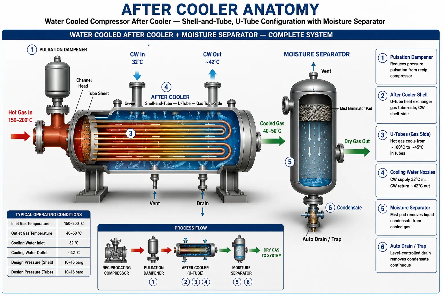
Pulsation Dampener (Reciprocating Compressors)
A vessel or manifold installed between the reciprocating compressor discharge valves and the after cooler inlet nozzle. The pulsation dampener absorbs the pressure pulses generated by the opening and closing of compressor discharge valves — which can cause vibration, fatigue failure of piping and instrumentation, and flow measurement errors — smoothing the gas flow before it enters the after cooler bundle. Designed per API 618 pulsation and vibration analysis for reciprocating compressors.
After Cooler Heat Exchanger Shell
The pressure-containing outer vessel of a water cooled after cooler — cylindrical carbon steel or stainless steel shell designed per ASME Section VIII with shell-side nozzles for cooling water inlet and outlet. The shell houses the tube bundle, baffles, and tie rods, and is connected to the front channel head (where the gas nozzles are) and the rear floating head or U-tube bundle housing. NACE MR0175 compliant shell specification for sour gas service.
Tube Bundle — Gas-Side Tubes
The heat transfer core of the water cooled after cooler — seamless tubes through which compressed gas flows at design pressure and temperature, rejecting heat through the tube wall to cooling water on the shell side. U-tube configuration allows thermal expansion without a fixed tube sheet on the hot end, preventing tube-to-tube sheet joint stress from large gas-to-water temperature differences. Tube material selected for gas composition, pressure, and temperature — carbon steel SA-179/SA-213 for clean gas, 316L SS for corrosive or sour gas.
Channel Head and Gas Nozzles
The bolted pressure enclosure at the gas inlet end of the after cooler shell — contains the pass partition plate that directs gas through the first tube-side pass (inlet side of U-tubes) and receives it from the second pass (return side of U-tubes) before delivering it to the gas outlet nozzle. Gas inlet and outlet nozzles are sized for the compressor discharge flow rate at the specified allowable pressure drop. ASME B16.5 flanged nozzles in the correct pressure class for the final discharge pressure.
Segmental Baffles and Tie Rods
Segmental baffles inside the shell direct the cooling water in a cross-flow pattern across the tube bundle — increasing cooling water velocity, improving the shell-side heat transfer coefficient, and supporting the tubes against vibration. For gas compression service, anti-vibration baffle designs (double segmental or NTIW — No Tubes In Window) are specified where high flow-induced vibration risk is predicted from the acoustic velocity of the compressed gas.
Moisture Separator / Knockout Drum
A vertical or horizontal pressure vessel installed directly downstream of the after cooler outlet nozzle — designed and sized as a pressure vessel per ASME Section VIII, rated for the full after cooler design pressure. Internal components include a wire mesh mist eliminator pad (or vane pack for high-velocity gas) to capture liquid droplets from the cooled gas stream. A level gauge or level transmitter monitors the condensate level; an automatic level-control drain valve or steam trap discharges condensate continuously. Critical sizing parameter: gas velocity through the mist pad must be below the entrainment velocity limit, calculated from the Souders-Brown equation.
Automatic Condensate Drain System
Condensate collected in the moisture separator is continuously removed through an automatic drain system — a float-operated mechanical drain trap, or an electrically-actuated automatic drain valve controlled by a level transmitter. The drain system must handle the condensation rate at design conditions without allowing liquid build-up in the separator that would re-entrain liquid into the outlet gas stream or — in sour gas service — without allowing a liquid slug to accumulate and be released suddenly into downstream equipment.
Gas Outlet Temperature Indicator
A thermowell and temperature transmitter installed on the after cooler gas outlet nozzle or moisture separator gas outlet — the primary control measurement for the after cooler system. In air cooled after coolers with auto-variable fans, this signal drives the blade pitch control loop to maintain the gas outlet temperature at setpoint across the full range of ambient temperature variation. In water cooled after coolers, this signal drives the cooling water flow control valve. A high-temperature alarm and — where required by process safety — a high-high temperature shutdown is derived from this measurement.
After Cooler vs Inter Cooler — Key Differences
| Parameter | After Cooler | Inter Cooler |
|---|---|---|
| Position in Compression Train | After the final compression stage — on the compressor final discharge | Between compression stages — between Stage 1 and Stage 2, Stage 2 and Stage 3, etc. |
| Number per Compressor | One per compressor unit (installed on the final discharge) | (N − 1) inter coolers for an N-stage compressor — a 3-stage compressor has 2 inter coolers |
| Primary Purpose | Reduce final discharge gas temperature to a safe downstream operating temperature; condense and remove moisture and heavy hydrocarbons before delivery to the pipeline or process | Cool partially compressed gas between stages to reduce compression work in the next stage; keep interstage gas temperature within compressor cylinder and packing mechanical limits |
| Inlet Gas Pressure | Full final discharge pressure of the compressor | Interstage pressure — lower than final discharge, higher than suction |
| Inlet Gas Temperature | Final stage discharge temperature — typically highest in the system | Intermediate stage discharge temperature — lower than final stage |
| Gas Outlet Temperature Requirement | Must meet downstream process, pipeline, or storage specification — often governed by moisture dew point or equipment temperature limit | Must be below the next stage suction temperature limit — typically 35–45°C to keep compression work minimised |
| Moisture Separator | Always provided — moisture and condensate must be removed before gas enters downstream system | Usually provided — condensate at interstage must be removed to prevent compressor liquid ingestion damage |
| Design Standard | ASME Section VIII; API 661 (air cooled) or API 660 (water cooled); TEMA; NACE where applicable | Same design standards — the distinction is process position only, not the mechanical design approach |
Engineering Note: The terms after cooler and inter cooler describe position in the compression train — not a different type of heat exchanger. An after cooler and an inter cooler on the same compressor may be mechanically identical shell-and-tube heat exchangers, differing only in their design pressure, gas inlet temperature, and gas flow rate. In compressor OEM packages, the after cooler and inter coolers are often the same hardware design, with different pressure ratings applied to each unit.
After Coolers for Each Compressor Type
Reciprocating Compressor After Cooler
High discharge temperature — pulsation dampener — sour gas ratedReciprocating compressors produce the highest discharge temperatures of any compressor type — adiabatic discharge temperatures of 150–200°C are typical — and introduce significant pressure pulsations on the discharge line. After coolers for reciprocating compressors must therefore handle the highest inlet temperatures, be connected through a pulsation dampener (per API 618), and are most commonly found in natural gas gathering, gas lift, gas injection, and pipeline booster service at pressures from 20 to 400 bar.
- Gas inlet temperature: 150–200°C — highest of any compressor type
- Pulsation dampener required between compressor discharge and after cooler inlet — API 618 torsional and pulsation study
- High design pressure — single-stage reciprocating compressors commonly discharge at 20–50 bar; multi-stage up to 400 bar for high-pressure service
- Water cooled shell-and-tube design most common; air cooled for remote and pipeline stations
- NACE MR0175 for sour natural gas service — mandatory hardness control and PWHT
- Vibration analysis: after cooler structural and piping design reviewed against API 618 Chapter 7 allowable vibration levels
Centrifugal Compressor After Cooler
Large gas flow — continuous duty — air or water cooledCentrifugal compressors handle very large gas flows continuously at moderate discharge pressures — typically 5–50 bar in process plant service. Discharge temperatures are lower than reciprocating compressors (80–160°C) and there are no pressure pulsations, simplifying the after cooler mechanical design. After coolers for centrifugal compressors are sized for large gas mass flow rates and are typically the largest after coolers in any compression facility — handling the full output of a high-flow centrifugal machine in a single shell or multiple parallel shells.
- Gas inlet temperature: 80–160°C — lower than reciprocating, higher gas mass flow rate per unit
- No pulsations — smooth, continuous flow allows more compact nozzle and piping design
- Large gas flow rate — multiple parallel shells or wide bundle designs for large centrifugal compressors in LNG, refinery, and pipeline service
- Air cooled after coolers with multiple fan bays — standard for large centrifugal compressors in gas processing and LNG plants
- Anti-vibration baffle design review recommended for high-velocity gas on the tube side of water cooled designs
- Variable frequency drive (VFD) fan control for air cooled units — maintains precise gas outlet temperature across ambient variation
Screw Compressor After Cooler
Oil-injected or oil-free — compressed air and process gasScrew compressors are the dominant technology for industrial compressed air systems and are increasingly used for natural gas and process gas compression. Oil-injected screw compressors have particularly high discharge temperatures (80–110°C) — the injected oil cools the compression process but exits with the compressed air as a fine aerosol that must be removed. After coolers for screw compressors must therefore handle both the heat removal and the oil coalescing function — sometimes combined in a single unit with integral oil separator.
- Oil-injected screw: gas outlet from compressor contains oil aerosol at 80–110°C — after cooler cooling triggers oil coalescence and separation
- Oil-free screw: higher discharge temperature (150–180°C) without oil injection — similar after cooler duty to reciprocating service
- Compact water cooled shell-and-tube after coolers for packaged industrial compressor skids
- Air cooled after cooler finned tube coil integrated into the compressor enclosure for small and medium screw compressors
- Integral oil separator combined with moisture separator for oil-injected screw compressor packages
- Applications: compressed air for instrumentation and pneumatics, nitrogen generation, refrigerant gas compression, biogas compression
Moisture Separator — Design and Function
The moisture separator — also called an after cooler separator, knockout drum, or condensate separator — is the vessel installed directly downstream of the after cooler to remove liquid water and hydrocarbon condensate from the cooled compressed gas stream. It is as important to the after cooler system as the heat exchanger itself: a correctly sized and designed moisture separator is the difference between dry, clean compressed gas and a downstream pipeline full of liquid water that corrodes, slugs, and contaminates.
Gravity Separation Zone
The gas enters the separator at reduced velocity — the separator internal diameter is sized so that the gas upward velocity is below the critical velocity at which liquid droplets would be carried upward by the gas stream instead of falling to the bottom under gravity. Large droplets (above approximately 300–500 µm) disengage by gravity alone in this zone and fall to the liquid sump without needing the mist eliminator.
Mist Eliminator Pad (Wire Mesh or Vane Pack)
Fine liquid mist droplets (10–300 µm) that are not captured by gravity alone are removed as the gas passes through a mist eliminator — either a knitted wire mesh pad (for droplets above approximately 3–10 µm at moderate velocities) or a vane pack (for higher-velocity gas streams or applications where mesh plugging from liquid hydrocarbon is a risk). The mist eliminator coalesces fine droplets into larger ones that drain back to the separator sump by gravity.
Liquid Sump and Level Control
Liquid water and hydrocarbon condensate collect in the sump at the bottom of the separator vessel. A level gauge or level transmitter monitors the liquid level. An automatic drain valve — typically a float-controlled mechanical trap for continuous service, or an electrically actuated ESD-rated valve for sour or hazardous liquid — removes the condensate continuously. The sump volume is sized for the maximum condensation rate at design conditions with adequate hold-up time between drain cycles.
Souders-Brown Velocity Sizing
The correct internal diameter for the moisture separator is determined by the Souders-Brown equation: U_max = K × √[(ρ_L − ρ_G) / ρ_G], where U_max is the maximum allowable superficial gas velocity, ρ_L and ρ_G are the liquid and gas densities, and K is a factor depending on the separator internal (0.04–0.12 m/s for wire mesh with no entrainment). Operating gas velocity should be 75–85% of U_max — too low causes liquid pooling in the mist pad; too high causes liquid carryover into the outlet gas.
Design Pressure = After Cooler MAWP
The moisture separator is a pressure vessel — it must be designed, fabricated, and certified to ASME Section VIII at the same MAWP as the after cooler it serves. Any pressure vessel downstream of a compressor final stage is exposed to the full final discharge pressure, and the moisture separator design must reflect this. NACE MR0175 material requirements and PWHT apply to the moisture separator in sour gas service exactly as they apply to the after cooler itself.
Condensate Rate Estimation
The moisture separator must handle the maximum condensation rate occurring at the lowest expected after cooler gas outlet temperature (lowest ambient, or maximum cooling water flow, worst-case). For air, the condensate rate can be calculated from psychrometric relationships (air inlet humidity × mass flow × [humidity ratio at inlet – humidity ratio at outlet conditions]). For natural gas, condensate rates are calculated from phase equilibrium using the gas composition and the after cooler outlet temperature and pressure using a process simulator or correlation.
Design Specifications and Standards
After Cooler — Standard Design Parameters (United Heat Exchangers)
Material Selection Guide
Carbon Steel SA-179 / SA-213 — Standard Gas Service
The default tube material for after coolers handling clean compressed air, sweet natural gas, nitrogen, CO₂ (dry), and non-corrosive process gas. SA-179 is the standard seamless carbon steel condenser tube specification; SA-213 T1a/T1b for slightly higher temperature service. Corrosion allowance of 1.5–3.0 mm added to calculated wall thickness. PWHT required for NACE service and for shell wall above 19 mm per ASME UCS-56.
Carbon Steel SA-516-70 Shell and Heads
The standard shell and head plate material for water cooled after coolers in clean gas and cooling water service. SA-516-70 normalised carbon steel offers good toughness down to −29°C. For sour gas after coolers, SA-516-70 must be HIC-tested (Hydrogen Induced Cracking resistant) per NACE TM0284 — standard SA-516-70 plate is not acceptable in H₂S-containing service without HIC qualification. PWHT of all welds mandatory in sour gas service regardless of wall thickness.
316L Stainless Steel — Sour Gas and Corrosive Service
SA-312 TP316L tubes and SA-240 316L plate for shell components are specified for after coolers handling corrosive compressed gas — sour gas above NACE hardness limits of carbon steel, CO₂-rich gas with water condensate (carbonic acid corrosion), chlorinated gas, and amine-contaminated streams. 316L stainless eliminates the PWHT requirement that complicates carbon steel construction in sour service, and has far superior resistance to CO₂ and chloride-bearing condensate.
Cr-Mo Low-Alloy Steel — Hydrogen Service
SA-213 Grade T-11 (1.25 Cr, 0.5 Mo) and T-22 (2.25 Cr, 1 Mo) for after coolers in hydrogen-rich gas service — where the Nelson curve (API 941) for the operating temperature and hydrogen partial pressure requires a Cr-Mo steel rather than plain carbon steel. Mandatory PWHT for all Cr-Mo welds. Used for hydrogen compressor after coolers in refineries, hydrogen fuelling stations, and electrolysis plant compression. F-11 and F-22 forgings for flanges and nozzle necks in hydrogen service.
Duplex 2205 — Wet CO₂ and Offshore Service
SA-790 S31803 duplex stainless steel tubes and SA-240 S31803 plate for after coolers in wet CO₂ compression (EOR injection) and offshore production gas compression where the combination of CO₂, H₂S, and chlorides in the gas condensate creates a highly corrosive environment that exceeds the corrosion resistance of 316L stainless. Duplex offers approximately twice the yield strength of 316L — enabling thinner tube walls for the same pressure rating.
Copper-Nickel — Seawater-Cooled After Coolers
C70600 (90/10 Cu-Ni) or C71500 (70/30 Cu-Ni) tubes for the cooling water side of after coolers where direct seawater is used as the coolant — offshore platforms, marine vessels, and coastal gas compression stations. Copper-nickel shell-side tubes or shell-side tube inserts resist seawater corrosion, pitting, and biofouling far better than carbon steel or stainless steel in direct seawater service.
Engineering Advantages of a Properly Designed After Cooler
Protects All Downstream Equipment
A correctly designed and operating after cooler is the single most important piece of protection for every component downstream of the compressor — piping, valves, instruments, storage vessels, and process equipment — all of which are designed for temperatures well below the compressor discharge temperature.
Eliminates Liquid Carryover into Downstream Pipeline
The after cooler plus moisture separator removes essentially all liquid water and condensate from the compressed gas stream before it enters the downstream distribution network — preventing corrosion, slug flow, instrument damage, and process contamination that unconditioned wet gas would cause.
Improves Gas Quality for Pipeline Specification
Cooling the gas in the after cooler brings it below its water and hydrocarbon dew points — allowing the separator to remove condensed components and deliver a gas stream that meets pipeline water content and hydrocarbon dew point specifications. This is not optional for gas export — it is a contractual quality requirement.
Reduces Pipeline Pressure Drop
Gas at 45°C is approximately 35% denser than gas at 150°C at the same pressure. Delivering cooler gas to the pipeline reduces gas velocity for the same mass flow rate, reducing frictional pressure drop — allowing the same pipeline to carry more gas, or allowing a smaller pipeline to carry the same gas flow.
Increases Gas Storage Vessel Capacity
A compressed gas storage vessel holds a fixed volume. Cooler gas at higher density stores more mass in the same vessel volume. Cooling compressed air to 45°C instead of 150°C before entering a buffer vessel increases the stored gas mass — and the effective storage time — by approximately 25–30%.
Enables Accurate Flow Metering
Ultrasonic, orifice plate, and turbine flow meters all require the gas temperature to be known accurately for flow calculation. Delivering gas to the meter at a stable, well-defined temperature (the after cooler outlet) rather than at a variable, high compressor discharge temperature ensures accurate metering and reduces correction errors in custody transfer measurement.
Reduces Compressor Maintenance Frequency
Removing moisture, oil aerosol, and heavy hydrocarbon condensate from the gas before it enters downstream equipment also protects downstream compressors in multi-compressor systems, downstream instruments, and downstream filters from premature fouling and failure — reducing maintenance frequency and unplanned shutdowns across the entire gas compression and distribution system.
Fire and Explosion Safety in Compressed Air
In compressed air systems with any risk of oil carry-over from the compressor, high-temperature gas entering a storage vessel or distribution system creates auto-ignition risk. Cooling the air to below 50°C in the after cooler eliminates this risk — compressed air at 45°C is safe; at 180°C with oil vapour carryover, it is a potential fire source in any ignition-prone environment.
Industries and Applications
Every compressor in every industry that delivers compressed gas to a downstream system requires an after cooler. United Heat Exchangers designs and supplies after coolers for the following industries and specific compressor applications.
| Industry / Application | After Cooler Type | Compressed Gas | Key Design Features |
|---|---|---|---|
| Natural Gas Pipeline Compression | Air cooled after cooler — multi-bay, large fin fan units | Sweet or sour natural gas — 20–80 bar discharge pressure | API 661, auto-variable pitch fans, NACE MR0175 for sour gas, integral moisture separator, skid-mounted |
| Gas Lift Compression | Air cooled or water cooled after cooler | Associated gas, natural gas — 60–200 bar for high-pressure gas lift | High design pressure, compact for platform installation, NACE sour service, minimal weight for offshore |
| Gas Injection / EOR | Water cooled shell-and-tube after cooler | Natural gas or CO₂ — 200–400 bar injection pressure | Very high design pressure, ASME Div. 2 for above 200 bar, duplex or 316L SS for wet CO₂ service |
| CNG Fuelling Station | Water cooled after cooler (high-pressure) | Natural gas — 250–300 bar discharge for CNG vehicle fuelling | 250–300 bar design pressure, compact skid mount, carbon steel or SS, integral moisture separator |
| Refinery Process Gas Compression | Water cooled shell-and-tube — TEMA-R | Hydrogen-rich reformer gas, recycle gas, fuel gas — 10–150 bar | API 941 Nelson curve compliance for hydrogen service, Cr-Mo tube material, PWHT, NACE for sour |
| Instrument and Plant Air | Water cooled or air cooled after cooler | Compressed air — 7–10 bar (instrument air), 7–25 bar (plant air) | Carbon steel, ASME Section VIII, integral moisture separator, automatic drain trap, low pressure |
| Ammonia Synthesis (Fertiliser) | Water cooled shell-and-tube after cooler | Syngas (N₂ + H₂) — 150–300 bar synthesis loop pressure | High-pressure, Cr-Mo tubes for hydrogen service, very clean gas — low fouling, all-stainless for syngas purity |
| Offshore Platform Gas Compression | Air cooled or seawater cooled after cooler | Associated gas — 20–150 bar | Compact for deck weight limits, seawater-cooled (Cu-Ni tubes) or small air cooled, NACE sour service, EEx-rated instruments |
| LNG Plant Boil-Off Gas Compression | Air cooled after cooler — cryogenic duty reversal | LNG boil-off gas (BOG) — predominantly methane at very low temperature | Low-temperature design, impact-tested materials, 9% Ni or 304L SS for cryogenic, special consideration of gas warming on startup |
| Biogas / Landfill Gas Compression | Water cooled shell-and-tube after cooler | Biogas (CH₄ + CO₂ + H₂S + moisture) — 5–20 bar | 316L SS or duplex for H₂S + CO₂ + moisture combination; NACE for H₂S above threshold; integral condensate separator with automatic drain |
How to Select an After Cooler
Define the Compressor Discharge Conditions
The after cooler thermal sizing begins with five compressor discharge parameters: gas name and composition (mol%), mass flow rate (kg/hr or Nm³/hr), discharge pressure (bar gauge), discharge temperature (°C), and molecular weight. These are read directly from the compressor performance curve or datasheet and form the after cooler inlet conditions. The compressor OEM data sheet is the most reliable source — measured discharge temperatures should be used in preference to calculated adiabatic values, which are always lower than actual due to mechanical losses.
Specify the Required Gas Outlet Temperature
The required gas outlet temperature is set by: (a) the maximum inlet temperature of downstream equipment — typically 50°C for instruments and control valves; (b) the pipeline gas temperature specification — typically 45–50°C for onshore pipelines; (c) the water dew point specification — the outlet temperature must be below the water dew point at line pressure to allow moisture separation; or (d) the hydrocarbon dew point specification for gas export. The most restrictive of these conditions sets the required after cooler gas outlet temperature.
Choose Cooling Medium — Air or Water
Select air cooling if cooling water is unavailable, the site is remote or the installation is a gas compression station or pipeline facility, and the required gas outlet temperature can be met by an air cooled unit at the design ambient temperature. Select water cooling if cooling water is available and reliable, the required gas outlet temperature is below 50°C in a hot climate (design ambient above 40°C), or the plot area available is too small for an air cooled unit.
Check for Sour Gas or Special Material Requirements
If the compressed gas contains H₂S at any concentration above the NACE MR0175 threshold (typically >0.0003 MPa H₂S partial pressure in wet gas), all pressure-containing components must comply with NACE MR0175 / ISO 15156 — hardness limits, PWHT, and HIC-tested plate. Hydrogen service requires API 941 Nelson curve check. CO₂ + water service requires 316L SS or duplex. These requirements must be confirmed before material selection is finalised.
Size the Moisture Separator
Estimate the condensation rate at the after cooler outlet conditions using psychrometrics (for air) or process simulation (for natural gas and process gas). Size the moisture separator internal diameter from the Souders-Brown equation using the gas density at outlet conditions. Select a wire mesh mist eliminator pad or vane pack based on gas velocity and liquid loading. Size the liquid sump and auto drain for the expected condensate rate with an appropriate hold-up time between drain cycles.
Confirm Pulsation Analysis (Reciprocating Compressors)
For reciprocating compressor after coolers, confirm that a pulsation dampener of adequate volume is specified between the compressor discharge and the after cooler inlet nozzle — per API 618 Chapter 3 or 7 analog study. The after cooler inlet nozzle must not be positioned at an acoustic resonance of the piping system. After cooler mechanical and piping design must comply with API 618 allowable pulsation-induced vibration levels to prevent fatigue failure of the after cooler shell, nozzles, and associated piping during continuous operation.
Maintenance and Cleaning Guide
Gas-Side Tube Cleaning (Water Cooled)
In water cooled after coolers where the compressed gas contains oil carryover from the compressor — oil-injected screw compressors and lubricated reciprocating compressors — the gas-side tube bore accumulates an oil and hydrocarbon deposit over time that reduces heat transfer and increases gas-side pressure drop. High-pressure water jet cleaning or mechanical brush cleaning through the gas inlet channel head (U-tube bundles) removes this deposit. Frequency: annually or at each compressor major overhaul, whichever comes first.
Cooling Water-Side Scale Removal (Water Cooled)
Calcium carbonate scale deposits from hard cooling water on the shell side of water cooled after coolers reduce heat transfer and increase cooling water pressure drop over time. Chemical descaling — circulating 5–10% inhibited hydrochloric acid or citric acid through the shell side — dissolves scale deposits efficiently without damaging the tube exterior or shell. The shell side is accessible without tube bundle removal in BEM and BEW designs; U-tube bundles can be pulled for external cleaning if required.
Air Cooled After Cooler Fin Cleaning
Air cooled after cooler finned tube bundles in dusty environments (desert locations, cement plants, agricultural areas) accumulate dust between fin pitches, progressively increasing air-side pressure drop and reducing air-side heat transfer coefficient. High-pressure water jetting — directed at 45–60° to the fin surface from the air inlet face — removes accumulated deposits. Never jet at 90° to the fin surface — this bends the aluminium fins. Frequency: quarterly inspection; cleaning as required (typically semi-annually in clean environments, more frequently in dusty locations).
Moisture Separator Mist Eliminator Inspection
The mist eliminator pad or vane pack in the moisture separator must be inspected at each shutdown opportunity for plugging, corrosion, and mechanical damage. A plugged mist eliminator increases the gas-side pressure drop through the separator, reduces the effective gas velocity for liquid disengagement, and — if the pad collapses — allows entrainment of liquid into the outlet gas stream at high velocity with potentially severe erosion of downstream equipment. Replace wire mesh mist eliminator pads on a 3–5 year cycle in clean gas service; earlier in dirty or corrosive gas service.
Auto Drain System Testing
The automatic condensate drain system on the moisture separator must be tested and verified as fully operational at every scheduled maintenance opportunity — a failed-closed drain valve is the single most common cause of liquid accumulation in the separator leading to liquid carryover into the downstream pipeline. Test by manual operation of the drain valve, observation of condensate flow, and verification that the level control system drives the valve closed when the sump is empty. Float-operated mechanical traps must be disassembled and inspected for float integrity, seat condition, and free movement at each annual service.
UT Wall Thickness Survey (Corrosive Service)
After coolers in sour gas, wet CO₂, biogas, and other corrosive gas service must be surveyed by ultrasonic thickness (UT) measurement at each major turnaround — typically every 2–4 years depending on the corrosion rate. UT measurements at the gas inlet tube end (where erosion-corrosion rates are highest due to high entry velocities), at bends in U-tube bundles, and on shell wall and nozzle tees confirm remaining wall thickness against the minimum required wall calculation. Any location showing a remaining wall below the calculated minimum corrosion allowance requires repair or replacement before return to service.
Why United Heat Exchangers for After Coolers
Compressor OEM and End-User Experience
United Heat Exchangers supplies after coolers to both compressor OEMs (as package-integrated after coolers for new compressor units) and directly to end-users (as replacements and upgrades on existing compression facilities). This dual experience gives us a thorough understanding of the mechanical interface requirements — pulsation dampener connections, nozzle orientations, skid footprint constraints, and vibration isolation — that distinguish a well-integrated after cooler from a heat exchanger that merely fits the flange rating.
Full Thermal Design in HTRI
Every after cooler thermal design is performed in HTRI Xchanger Suite — gas-side and coolant-side heat transfer, pressure drop, tube vibration check, and two-phase performance at condensing conditions. The moisture separator sizing calculation is provided alongside the heat exchanger thermal rating, with Souders-Brown velocity check and condensate rate estimation at design and worst-case conditions.
ASME U-Stamp — All Pressure Parts
After cooler shells, tube bundles, moisture separators, and pulsation dampeners are all fabricated to ASME Section VIII Division 1, independently inspected by our Authorised Inspection Agency, and U-Stamped — with Manufacturer's Data Reports (U-1 Forms) issued for each pressure-containing vessel in the after cooler system.
NACE MR0175 Sour Service Expertise
After coolers in sour natural gas service demand a level of materials knowledge and quality control discipline that goes well beyond standard heat exchanger fabrication. We maintain full NACE MR0175 / ISO 15156 compliance documentation — material data sheets, hardness certifications, PWHT records, and HIC test reports — for every sour gas after cooler, with third-party NACE inspector witness available on request.
Complete After Cooler Systems
We design and supply complete after cooler systems — heat exchanger, moisture separator, auto drain valve, level gauge, pressure gauge, safety relief valve, interconnecting nozzles, and structural support frame — as an integrated package, not as individual components from separate vendors. This single-vendor approach simplifies your procurement, ensures dimensional and pressure rating compatibility between all components, and delivers a single documentation package covering the entire system.
Export to 30+ Countries
After coolers and inter coolers supplied for gas compression facilities across the Middle East, Southeast Asia, Africa, and India — with ASME, API 661, API 660, NACE MR0175, and client-specified standards as required. Export packing, marine insurance, and freight documentation managed in-house with 35+ years of export experience.
Get a Free After Cooler Quote in 48 Hours
Share your compressor datasheet (gas composition, mass flow, discharge pressure, discharge temperature), required gas outlet temperature, cooling medium (air or water), site ambient temperature, and any NACE or API requirements. Our team provides HTRI thermal sizing, moisture separator design, and a complete technical and commercial proposal within 48 hours.
Request My Free Quote →Delivery and What's Included
What's Included with Every After Cooler Order
- HTRI thermal performance documentation — gas-side and coolant-side heat transfer and pressure drop rated at design conditions; tube vibration check; condensing performance curve at range of gas outlet temperatures from winter minimum to summer maximum ambient
- Moisture separator sizing calculation — Souders-Brown gas velocity check, mist pad pressure drop, condensate rate at design conditions, sump volume and hold-up time, auto drain sizing — complete with design basis document
- ASME U-Stamp and Manufacturer's Data Report (Form U-1) — for all pressure-containing components: after cooler shell and tube bundle, moisture separator, pulsation dampener — signed by Authorised Inspector
- NACE MR0175 compliance documentation — for sour gas after coolers: material data sheets with hardness certification, PWHT records with calibrated chart records, HIC test reports for plate material, bolting specification (A193 B7M / A194 2HM), NACE compliance matrix covering every pressure-containing component
- API 941 Nelson curve compliance check — for hydrogen service after coolers: confirmation that specified tube material is acceptable at design temperature and hydrogen partial pressure, with material trace to certified mill test report
- Material certifications (MTRs) — traceable mill test reports for all pressure-containing materials: tube, shell plate, tube sheet, nozzle pipe, and flanges — chemistry and mechanical properties confirmed against ASTM specification
- NDE reports — RT or UT of all pressure-containing butt welds; MT or PT of all fillet and attachment welds; hardness survey of all welds and HAZs (NACE service); signed by ASNT Level II certified inspector
- Hydrostatic test certificate — witnessed by Authorised Inspector; gas-side and shell-side pressure circuits each hydrostatically tested to 1.3× MAWP with no leaks or permanent deformation
- Vibration analysis (reciprocating compressor) — pulsation dampener sizing calculation confirming volume compliance with API 618; structural natural frequency check of after cooler support frame against compressor running speed harmonics
- Certified general arrangement drawing — overall unit dimensions, nozzle schedule with orientation and projection, separator dimensions and nozzle layout, drain and instrument connection locations, support footprint and anchor bolt pattern, lifting lug locations and shipping weight
- Operations and maintenance manual — commissioning procedure (venting, pressure testing, first gas-up), normal operating parameters, gas outlet temperature alarm and shutdown setpoints, tube cleaning procedure, moisture separator mist pad inspection interval, auto drain testing procedure, and spare parts list for 2 years of operation
- Lifetime technical support — thermal re-rating for changed compressor capacity or gas composition, tube bundle replacement sizing, NACE compliance review for changed H₂S partial pressure, and fitness-for-service assessment throughout the after cooler's operating life
Frequently Asked Questions — After Coolers
What is an after cooler?
An after cooler (also written aftercooler) is a heat exchanger installed on the final discharge of a compressor to cool the compressed gas or air back to a safe, usable temperature before it enters the downstream piping, storage, or process system. Compressor discharge gas exits at 80–200°C depending on compressor type, number of stages, and compression ratio. The after cooler reduces this temperature to approximately 40–60°C — removing the heat of compression, causing water vapour and hydrocarbon condensate to condense, and protecting all downstream equipment from the thermal and moisture damage that unconditioned hot compressed gas would cause.
What is the difference between an after cooler and an inter cooler?
An after cooler is installed after the final compression stage — on the compressor final discharge — and cools the fully compressed gas to its delivery temperature. An inter cooler is installed between compression stages in a multi-stage compressor, cooling partially compressed gas between stages to reduce the work required for the next stage and to keep interstage temperatures within compressor mechanical limits. A 3-stage compressor therefore has 2 inter coolers (between stages 1–2 and 2–3) and 1 after cooler (on the final stage 3 discharge). Both are heat exchangers of essentially the same design — the distinction is position in the compression train, not equipment type.
What gas outlet temperature does an after cooler achieve?
A water cooled after cooler with a 32°C cooling water supply temperature typically achieves a gas outlet temperature of 40–47°C (8–15°C approach to the cooling water temperature). An air cooled after cooler with a 45°C design ambient temperature typically achieves a gas outlet temperature of 55–62°C (10–17°C approach to the ambient dry-bulb). When the required gas outlet temperature is below what an air cooled unit can achieve, a combined air/water after cooler system is used — the air cooler handles the bulk duty and a water cooled trim cooler achieves the final required temperature.
Why does an after cooler need a moisture separator?
As the compressed gas cools in the after cooler, water vapour — and in natural gas service, heavy hydrocarbon vapour — that was above its dew point at the high compressor discharge temperature condenses into fine liquid droplets. These droplets are carried out of the after cooler in the gas stream at outlet velocity. Without a moisture separator, this liquid enters the downstream pipeline or process system as fine mist — causing corrosion, instrument damage, slug flow in the pipeline, contamination of downstream process equipment, and valve and seal damage. The moisture separator, installed immediately downstream of the after cooler, removes these droplets by gravity and mist eliminator action before they can reach downstream equipment.
What standards apply to after cooler design?
After coolers are designed to the following standards: ASME Section VIII Division 1 for all pressure-containing components; API 661 for air cooled after coolers with finned tube bundles and axial flow fans; API 660 and TEMA for water cooled shell-and-tube after coolers; NACE MR0175 / ISO 15156 for all components exposed to H₂S-containing (sour) compressed gas; API 941 (Nelson curves) for the tube material selection in hydrogen-rich gas service; and API 618 for the pulsation dampener and vibration analysis requirements on reciprocating compressor packages. IBR applies to after coolers in steam-connected service in India.
What is the difference between an air cooled and a water cooled after cooler?
An air cooled after cooler uses ambient air driven by motor-driven fans to cool the compressed gas inside a finned tube bundle — requiring no cooling water, suitable for remote locations, and achieving a gas outlet temperature of approximately 55–65°C in a hot climate (45°C design ambient). A water cooled after cooler is a shell-and-tube heat exchanger using cooling water on the shell side to cool the compressed gas in the tubes — requiring a cooling water supply but achieving a lower gas outlet temperature of 40–47°C at the same ambient conditions. The choice depends on cooling water availability, required gas outlet temperature, plot space, and life-cycle cost.
What is a NACE after cooler and when is it required?
A NACE after cooler is an after cooler designed and fabricated with all pressure-containing materials complying with NACE MR0175 / ISO 15156 — the international standard governing material selection for equipment exposed to hydrogen sulphide (H₂S) in wet sour gas service. NACE requirements apply whenever the compressed gas contains H₂S at a partial pressure above 0.0003 MPa (approximately 0.05 psi H₂S partial pressure) in the presence of free water — the conditions under which sulphide stress corrosion cracking (SSCC) can cause catastrophic failure of high-hardness steels and welds. NACE after coolers require hardness-controlled tube and shell materials, post-weld heat treatment (PWHT) of all carbon steel welds, HIC-tested shell plate, NACE-compliant bolting, and full hardness certification in the documentation package.
What is the lead time for an after cooler from India?
Standard carbon steel water cooled or air cooled after coolers for sweet gas, compressed air, and non-sour service deliver in 6–10 weeks from order confirmation and approved drawings. After coolers for sour gas with full NACE MR0175 compliance, high-pressure CNG or hydrogen service units (above 100 bar), alloy after coolers in 316L SS or duplex, and complete after cooler systems with integral moisture separator and auto drain deliver in 12–20 weeks. Expedited schedules for plant turnaround, compressor package completion deadlines, and emergency replacement of failed units are available — contact our engineering team with your compressor datasheet and required on-site date for a confirmed delivery commitment.
Author: Senthil Kumar, Technical Director — United Heat Exchangers Pvt. Ltd. | Last Updated: June 2026