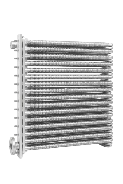
Finned Tube Heat Exchanger
A finned tube heat exchanger is a heat transfer device in which thin extended surfaces — called fins — are attached to the outer surface of heat exchanger tubes. The fins dramatically increase the effective heat transfer area without increasing the number of tubes or the overall footprint of the unit, making it possible to achieve large industrial heat duties with air or another gas as the cooling medium. The core engineering challenge that fins solve is the inherently low convective heat transfer coefficient of gases such as air (typically 30–80 W/m²·K) compared to liquids such as water (2,000–10,000 W/m²·K). By multiplying the outer surface area by a factor of 15 to 20 times compared to bare tubes, fins compensate for this low coefficient and produce a thermally efficient heat exchanger without the cost and complexity of a wet cooling system. 💡 Why finned tubes matter: Without fins, an air-cooled heat exchanger handling a large refinery or power plant heat load would require an impractically large number of bare tubes. A single finned tube with 10 fins per inch delivers roughly the same effective surface area as 15–20 bare tubes of the same length — this is the fundamental reason that finned tube construction dominates every large-scale air-cooled heat exchanger in the world. The operating principle of a finned tube heat exchanger combines conduction through the tube wall and fins with convection from the fin and tube surfaces into the surrounding gas stream — typically air. Understanding the two heat transfer paths is essential for correct thermal design and maintenance. Hot process fluid enters the header box through the inlet nozzle and is distributed uniformly across all tube inlets simultaneously by the header's internal distribution plenum. The process fluid flows through the finned tubes, transferring heat by conduction through the tube wall. The fluid-side (tube-side) resistance is typically low because liquids have high heat transfer coefficients. Heat conducted into the fin base travels along the fin by conduction. Simultaneously, fans force ambient air across the finned tube bundle, removing heat from the fin and bare tube surfaces by convection into the airstream. The cooled process fluid is collected in the outlet header box and exits through the outlet nozzle, returned to the process at the required temperature. In multi-pass units, partition plates redirect flow for additional cooling passes. 💡 The controlling resistance: In virtually every air-cooled finned tube heat exchanger, the air-side (gas-side) thermal resistance dominates the total resistance. This is why fin geometry — fin height, density, pitch, and material conductivity — is the primary design lever. The tube-side and wall resistances are almost always secondary. The choice of fin type governs thermal performance, mechanical durability, fabrication cost, and suitability for the operating temperature range. The four principal fin types used in industrial finned tube heat exchangers are: A continuous strip of aluminium is tension-wound in a helix around the tube. The L-foot or LL-foot locks the fin base to the tube surface. This is the most widely manufactured fin type worldwide — economical, reliable, and well-suited to fin densities of 8–11 FPI at operating temperatures up to 180°C. The fin is formed integrally from the tube wall material by an extrusion process — there is no interface between fin and tube. This eliminates contact resistance entirely and is used for all-aluminium tube construction. Fin densities of 10–12 FPI are achievable with excellent bond conductance from ambient to 180°C. A groove is machined helically into the tube outer surface, and the aluminium fin strip is rolled into the groove under pressure, creating a mechanical interference bond. This produces the highest fin-to-tube contact conductance among bi-metallic designs and is the preferred choice for high-temperature service above 200°C where wound fins would relax and lose thermal contact. For service conditions where aluminium cannot be used — high-temperature flue gas above 300°C, or fully corrosion-resistant construction — carbon steel or stainless steel fins are continuously welded to the tube. These accept lower fin efficiency (0.65–0.75 for CS fins) in exchange for temperature and corrosion capability. Used in waste heat recovery, flue gas coolers, and pharmaceutical service. The primary heat transfer element — a bare tube (carbon steel, stainless, or alloy) with fins applied to the outer surface. Tube pitch, diameter, length, and fin geometry all directly determine the thermal performance of the unit. Pressure vessel chambers at each end of the tube bundle. They distribute process fluid uniformly across all tube inlets, collect cooled fluid at the outlet, and form the pressure boundary for the tube-side fluid. Plug type or cover plate type depending on service pressure and fouling tendency. The structural frame supporting the tube bundle and headers. Designed to handle thermal expansion forces, fan loads, wind loads, and the weight of the tube bundle itself. Usually carbon steel with corrosion-resistant coating for outdoor service. Axial fans (forced draft or induced draft) drive ambient air across the finned tube bundle. Variable-pitch fans reduce energy consumption by 30–50% at partial load. Motor, gearbox, and fan blade pitch are all sized to the specific heat duty and local ambient temperature range. 💡 Engineering note: In forced draft units, fans are located below the tube bundle and push ambient air upward through the fins. In induced draft units, fans sit above the bundle and pull air through — this reduces hot air recirculation in closely spaced multi-bay installations and improves thermal performance in high-ambient temperature locations. The selection of tube and fin materials is governed by process fluid composition, operating temperature range, corrosion environment, and design pressure. The table below summarises the most common material combinations used in industrial finned tube heat exchangers. ⚠ Critical note on bimetallic fins: In wound aluminium fins on carbon steel tubes, galvanic corrosion at the fin-tube interface can progressively increase the contact resistance and degrade thermal performance. In coastal or offshore environments within 5 km of the sea, solid aluminium tubes with extruded fins, or tubes with a protective coating at the fin base, should be specified to prevent this degradation. Finned tube heat exchangers are engineered pressure systems — every tube, header, nozzle, and fin geometry must conform to internationally recognised codes and be verified by rigorous thermal and mechanical design calculations. United Heat Exchangers designs and fabricates to the following standards: The primary international standard for air-cooled heat exchangers. Specifies fin tube construction requirements, header box types, plug dimensions, tube-to-header joint methods, fan and motor specifications, vibration limits, and full hydrostatic test requirements at 1.5× design pressure. Governs pressure vessel design of the header boxes, cover plates, nozzle reinforcement, and weld joint efficiency. Division 2 design-by-analysis permits optimised wall thicknesses for high-pressure billet headers, often reducing total weight by 20–30%. Where finned tubes are used in shell-and-tube configurations (air-to-liquid or gas-to-gas), TEMA Class R, C, or B governs tube pitch, baffle spacing, and mechanical design of the shell. Most refinery-grade finned tube exchangers are TEMA Class R. Indian Standard (IS 2825) for unfired pressure vessels covers domestic project requirements. PED and CE marking are required for export to the European Union — both are routinely handled by United Heat Exchangers for international project delivery. All finned tube thermal designs at United Heat Exchangers are performed using HTRI Xace — the industry gold standard for air-cooled and gas-cooled heat exchanger rating and design. HTRI Xace simultaneously optimises fin geometry, tube count, tube passes, fan sizing, airside pressure drop, and vibration compliance to deliver the most economical design that meets all process and code requirements. The thermal performance of a finned tube heat exchanger is primarily controlled by how effectively the fins conduct and transfer heat — a property quantified through fin efficiency and overall surface efficiency. Understanding these parameters is essential for correct thermal design, material selection, and performance prediction throughout the service life of the unit. Measures how effectively a fin transfers heat relative to the theoretical ideal. Governed by fin geometry and material conductivity. Weights fin efficiency by the fin area fraction — the design parameter used to compute the overall heat transfer coefficient U. The convective coefficient on the gas side — typically 30–80 W/m²·K — is the dominant thermal resistance in all air-cooled designs. Aluminium at 205 W/m·K delivers superior fin efficiency. Carbon steel at ~50 W/m·K is substituted only where temperature demands it. How well a fin transfers heat is captured by fin efficiency (ηf) — the fraction of heat a fin actually dissipates compared to what it would dissipate if its entire surface stayed at the temperature of the tube base. For a fin with a constant cross-section, the classical one-dimensional solution for combined conduction along the fin and convection from the fin surface gives: where the fin parameter m = √(h · P / kfin · Ac). Each variable in this expression has a direct physical meaning: In a real finned tube, the total outer surface comprises both the fin area (Af) and the bare tube area between fins (Ab), giving a total surface Atot = Af + Ab. Because the fin surface does not operate at the full tube base temperature, it would be incorrect to apply ηf = 1.0 to the entire outer surface. The correct design parameter is the overall surface efficiency: This expression reduces the effective surface area in proportion to the fin area fraction and the degree to which the fin falls short of ideal performance. It is ηo — not ηf alone — that enters the calculation of the overall heat transfer coefficient U referenced to the full outer surface area, making it the key thermal design parameter for all finned tube sizing and rating calculations. The choice of fin material has a direct and substantial effect on ηf, and consequently on the required heat transfer area and capital cost of the finned tube unit: The combination of fin efficiency, overall surface efficiency, and the resulting achievable U-value determines which applications are economically viable for finned tube air-cooled construction: 📈 Design implication: A 10% reduction in fin efficiency (e.g., from ηf = 0.85 to 0.76) due to fin fouling, fin relaxation at elevated temperature, or substitution of carbon steel for aluminium increases the required heat transfer area by approximately 15–20% for the same heat duty and approach temperature — directly impacting capital cost. This is why fin material selection and fin bond integrity are taken seriously at the design stage. Finned tube heat exchangers are deployed wherever process fluids or gases must be cooled or heated efficiently using air or another gas as the secondary medium — spanning the most demanding thermal environments in global industry. Crude overhead condensers, product coolers, hydrogen coolers, compressor aftercoolers. Aluminium fins on CS tubes, API 661 design. NACE MR0175 for sour service. Reactor effluent coolers, distillation overhead condensers, hot oil coolers, amine regenerator condensers. High-alloy construction for corrosive process streams. Air-cooled condensers, turbine lube oil coolers, generator hydrogen coolers. Chrome-moly fins for high-temperature steam service; all-aluminium for ACC duty. Compression intercoolers and aftercoolers, dehydration unit coolers, amine regenerator condensers. Billet headers for high-pressure compression service. Charge-air coolers (intercoolers) and EGR coolers for diesel and gas engines. Compact, lightweight aluminium fin-on-tube designs for high heat rejection per unit volume. Weight-optimised aluminium or duplex SS finned tube units for offshore platforms. ABS/DNV-GL classified. Solid aluminium fins to prevent galvanic corrosion in salt spray. 316L stainless steel welded fin construction with electropolished surfaces and sanitary nozzles. GMP documentation and full material traceability for regulated industries. Ammonia synthesis loop coolers, urea process coolers, prilling tower air coolers. Corrosion-resistant tube and fin materials for ammonia-containing service. Selecting the correct fin type is as important as selecting the tube material. The table below provides a direct engineering comparison across all relevant factors. United Heat Exchangers manufactures API 661 & ASME certified finned tube heat exchangers in helical wound, embedded, extruded, and welded fin configurations — for all industries and all process conditions. Engineering review & quote within 48 hours. A disciplined maintenance programme preserves fin efficiency, tube integrity, and overall U-value throughout the service life of the finned tube heat exchanger and prevents unplanned shutdowns that cost far more than scheduled maintenance. A finned tube heat exchanger is a heat transfer device in which fins — thin extended metal surfaces — are attached to the outer surface of heat exchanger tubes to multiply the effective air-side heat transfer area by 15 to 20 times compared to bare tubes. This compensates for the low convective coefficient of air and makes air-cooled duty thermally viable for large industrial heat loads. Fin efficiency (ηf) is the fraction of heat a fin actually transfers relative to the theoretical maximum it would transfer if its entire surface remained at the tube base temperature. For a constant cross-section fin, ηf = tanh(m·Lc) / (m·Lc), where m = √(h·P / kfin·Ac). Aluminium fins achieve ηf above 0.85; carbon steel fins give 0.65–0.75. A lower ηf requires a larger bundle to achieve the same heat duty — so material selection directly affects capital cost. A wound fin is a strip of aluminium tension-wound around the tube with a mechanical L-foot lock — economical and suitable for service up to 180°C. An embedded (G-fin) is pressed into a groove machined into the tube surface, creating the highest fin-to-tube contact conductance of any bi-metallic design and maintaining its bond at temperatures up to 300°C or more, making it the preferred choice for high-temperature service. Aluminium (k ≈ 205 W/m·K) for standard service up to 180°C — it gives the highest fin efficiency and lowest cost. Carbon steel welded fins for service above 250°C where aluminium would soften, accepting ηf of 0.65–0.75. Stainless steel welded fins where both corrosion resistance and elevated temperature are required. Solid aluminium (extruded tube) for offshore and coastal locations where galvanic corrosion at the aluminium-steel fin-tube interface would degrade performance. Finned tube heat exchangers are used in oil and gas refining, petrochemical processing, natural gas compression, power generation, heavy-duty engine cooling (charge-air and EGR coolers), air-cooled condensers at arid-region power stations, waste heat recovery, fertilizer manufacturing, pharmaceutical production, food processing, and offshore platforms — wherever a fluid or gas must be cooled without cooling water. The most effective actions, in order of impact, are: clean fin surfaces to restore design airside pressure drop and h value; increase fan speed or blade pitch to raise air velocity across the bundle; add supplemental evaporative pre-cooling of inlet air during peak ambient periods; replace wound fins with embedded fins if high-temperature fin relaxation has increased contact resistance; and add tube rows if additional surface area is required for a changed heat duty. Yes. Every finned tube heat exchanger manufactured by United Heat Exchangers is custom-engineered to your specific process conditions — fluid type, flow rate, temperatures, design pressure, fin geometry, material, API 661 class, fouling service requirements, and code compliance. We provide free preliminary design review and budgetary pricing within 48 hours of receiving your process data sheet. United Heat Exchangers Pvt. Ltd is a leading Indian manufacturer of finned tube heat exchangers and air-cooled heat exchangers, with over 25 years of dedicated experience serving clients across refining, petrochemical, power, gas processing, offshore, and industrial manufacturing sectors. Every finned tube heat exchanger is designed, fabricated, inspected, and tested per API 661 and ASME Section VIII. We hold current ASME U-Stamp and R-Stamp authorisations. All units are hydrostatically tested at 1.5× design pressure before shipment. Full air-cooled finned tube thermal and mechanical design using HTRI Xace software — the industry gold standard. Designs are optimised simultaneously for U-value, fan power, fin geometry, fin efficiency, pressure drop, and vibration compliance to API 661 limits. All finned tube pressure parts supplied with EN 10204 3.1 or 3.2 mill certificates. Full PMI testing on all alloy components at goods receipt and post-fabrication. Complete material documentation package for every unit supplied. All header box pressure welds inspected by RT, UT, MPT, or DPT per ASME requirements. Tube-to-header joints strength-tested to API 661 pull-out requirements. Third-party inspection and expediting fully supported for major projects. Our finned tube air-cooled heat exchangers eliminate cooling water dependency entirely — saving 1,500–3,000 litres per megawatt-hour of heat rejected vs evaporative cooling towers. Variable-pitch fan designs reduce power consumption by up to 40% vs fixed-pitch alternatives. Free preliminary thermal design, fin type recommendation, material specification, and budgetary pricing within 48 hours of receiving your process data sheet. Our in-house engineering team handles all technical queries directly — no outsourcing. Share your process data — fluid type, flow rate, inlet and outlet temperatures, design pressure, site location, and fin type preference — and our engineering team will deliver a complete fin geometry recommendation, material specification, and budgetary quote within 48 hours. No obligation. Completely free. Related Products: Air Cooled Heat Exchanger | Air Fin Cooler | Finned Tube Heat Exchanger | Air Cooled Condenser | Compressor Cooler | Shell and Tube Heat Exchanger | Intercooler Author: Senthil Kumar, Technical Director — United Heat Exchangers Pvt. Ltd | Published: March 2026 | Category: Heat Exchanger Technical Guides | Tags: Finned Tube Heat Exchanger, Fin Efficiency, Aluminium Fins, Embedded Fins, API 661, ACHE, Air Fin CoolerTable of Contents
What Is a Finned Tube Heat Exchanger?
How Does a Finned Tube Heat Exchanger Work?
Fluid Entry
Tube-Side Flow
Fin Conduction & Air Convection
Cooled Fluid Exit
Types of Fins Used on Finned Tubes
Helical Wound (L-Foot / LL-Foot / KL-Foot)
Extruded (Mono-Metal)
Embedded (G-Fin)
Welded & Solid Stainless / Carbon Steel Fins
Key Components & Their Functions
Finned Tubes
Header Boxes
Tube Bundle Frame
Fan System
Materials of Construction — Tubes and Fins
Tube Material Fin Material Max Tube Temp Typical Application Carbon Steel (A179/A214) Aluminium (wound / embedded) 180°C (fin limit) Refinery, petrochemical, gas compression — the industry standard combination Carbon Steel Carbon Steel (welded) 400°C+ High-temperature flue gas coolers, waste heat recovery where Al fins would soften Stainless Steel 304/316L Stainless Steel 304/316L (welded) 500°C Pharmaceutical, food processing, corrosive gas cooling requiring full SS construction Chrome-Moly P11/P22 Carbon Steel (welded) 600°C Power plant steam coolers, high-temperature hydrogen service All-Aluminium (extruded) Aluminium (integral, extruded) 180°C Offshore platforms and coastal sites where bimetallic galvanic corrosion must be eliminated Duplex SS 2205 Duplex SS (welded) 315°C Offshore, chloride-laden environments, seawater-contaminated process streams Copper-Nickel 90/10 Copper-Nickel (welded) 250°C Marine and shipboard heat exchangers in seawater service Design, Construction & Engineering Standards
API 661
ASME Section VIII Div. 1 & 2
TEMA Standards
IS 2825 & PED 2014/68/EU
Thermal Design Software
Thermal Performance & Fin Efficiency
Fin Efficiency ηf
Overall Surface Efficiency ηo
Airside Coefficient h
Material Conductivity kfin
Fin Efficiency: Definition and Analytical Formula
Overall Surface Efficiency and the Heat Transfer Coefficient U
Material Impact on Fin Efficiency — Aluminium vs Carbon Steel
Key Industrial Applications Driven by Fin Efficiency
Industrial Applications of Finned Tube Heat Exchangers

Oil & Gas Refining

Petrochemical

Power Generation

Natural Gas Processing

Heavy-Duty Engines

Offshore & Marine

Pharmaceutical & Food

Fertilizer Plants
Key Features & Performance Parameters
Parameter Typical Range Governing Factor Impact on Performance Fin density (FPI) 8–12 fins per inch Airside pressure drop and fouling tendency Higher FPI = more area = better thermal performance but higher airside ΔP and fouling risk Fin height 10–25 mm (typical) Required surface area and fin efficiency constraint Taller fins give more area per tube but lower ηf; optimum balances both Fin efficiency ηf 0.65–0.90+ (material dependent) Fin material conductivity and geometry (m·Lc) Lower ηf requires larger bundle to achieve same heat duty Overall surface efficiency ηo 0.70–0.92 Fin area fraction and ηf Directly multiplies airside h in the U calculation — the key thermal design parameter Airside heat transfer coeff. h 30–80 W/m²·K (forced convection air) Air velocity across bundle and fin geometry Low h drives the need for fins; higher velocity increases h but increases fan power Overall heat transfer coeff. U 20–60 W/m²·K (air-cooled, referred to outer area) ηo, airside h, tube-side h, and fouling resistances Primary sizing parameter — determines required heat transfer area for a given duty Design pressure (tube side) 1 bar to 300 bar+ Header box type (plug, cover plate, billet) Sets wall thickness, plug specification, and tube-to-header joint type Design temperature −46°C to 650°C Tube and fin material selection Determines whether aluminium fins (≤180°C) or steel fins (up to 650°C) are applicable Fin Type Comparison: Helical Wound vs Embedded vs Extruded vs Welded
Factor Helical Wound (L/LL) Embedded (G-Fin) Extruded (Mono-Metal) Welded (Steel) Fin-tube bond Mechanical interference (L-foot) Mechanical groove lock — highest bond conductance Integral — no interface resistance Continuous weld — excellent bond Max operating temp 180°C (L-foot), 240°C (LL-foot) 300°C+ (groove maintains bond) 180°C (aluminium tube limit) 600°C+ (material dependent) Fin efficiency ηf 0.80–0.90 (Al fin) 0.82–0.92 (best bond conductance) 0.84–0.93 (no interface resistance) 0.65–0.75 (CS), 0.50–0.65 (SS) Galvanic corrosion risk Yes — Al fin / CS tube interface Yes — same bimetallic risk None — single metal construction None — same material fin and tube Fabrication cost Lowest — high-speed winding Medium — groove machining required Medium — extrusion tooling required Highest — continuous welding Best for Standard refinery and petrochemical service up to 180°C High-temperature service above 200°C requiring low contact resistance Offshore and coastal where galvanic corrosion must be eliminated Flue gas coolers, waste heat recovery, high-temperature corrosive service Need a Finned Tube Heat Exchanger for Your Plant?
Maintenance & Inspection Guide
Routine Operational Monitoring (Weekly)
Annual Shutdown Inspection Checklist
Fin Fouling & Cleaning Guide
Fouling Type Cleaning Method Frequency Prevention Dust & particulate Low-pressure compressed air blowing (max 3 bar); dry brush for delicate fins Monthly to quarterly depending on environment Install fine-mesh debris screens on air inlet face of the bundle Biological growth (algae, pollen, seeds) Low-pressure water wash with mild biodegradable detergent Quarterly to semi-annually Minimise vegetation proximity; consider biocide air treatment in severe cases Oil mist / hydrocarbon film Alkaline degreaser spray (low pressure); soft brush agitation; thorough water rinse Semi-annually or per inspection finding Locate finned tube bundle upwind of all hydrocarbon emission sources Salt crystallisation (coastal) Fresh water wash at low pressure to dissolve and flush salt; repeat until runoff conductivity equals fresh water Monthly for sites within 1 km of the sea Aluminium fin coating; solid aluminium or duplex SS fins for severe marine locations Fin relaxation (high-temperature wound fins) Cannot be reversed — affected tube sections must be replaced Detect by performance trending and eddy current inspection Specify embedded G-fins for service above 200°C; avoid wound fins above their rated temperature Frequently Asked Questions — Finned Tube Heat Exchangers
1. What is a finned tube heat exchanger?
2. What is fin efficiency and why does it matter?
3. What is the difference between embedded and wound fins?
4. What fin material should I use?
5. What industries use finned tube heat exchangers?
6. How do I improve the thermal performance of an existing finned tube unit?
7. Can United Heat Exchangers customise finned tube heat exchangers?
Why Choose United Heat Exchangers for Your Finned Tube Heat Exchanger?
API 661 & ASME Certified
HTRI Xace Thermal Design
Full Material Traceability
Comprehensive NDT
Sustainable, Water-Free Cooling
48-Hour Engineering Response
Ready to Specify Your Finned Tube Heat Exchanger?