Author: Senthil Kumar, Technical Director | Updated: May 2026
Table of Contents
- What Is an Air Receiver?
- How It Works in a Compressed Air System
- Types of Air Receivers
- Key Components Explained
- How to Size an Air Receiver: Formulas and Rules
- Design Specifications and Standards
- Material Selection Guide
- Industries and Applications
- How to Select the Right Air Receiver
- System Benefits of a Properly Sized Air Receiver
- Why United Heat Exchangers
- Delivery and What's Included
- Frequently Asked Questions
- Request a Free Quote
What Is an Air Receiver?
An air receiver — also called a compressed air storage vessel, air buffer tank, or air accumulator — is an ASME-certified pressure vessel that stores compressed air between the discharge of a compressor and the points of use in a pneumatic system. Its role is deceptively simple: hold a volume of pressurised air in reserve so the distribution system can absorb demand spikes, stabilise compressor cycling, and supply downstream equipment with steady, consistent pressure — regardless of how abruptly or unevenly that demand arrives.
Without a correctly sized receiver, a compressed air system is a system without a buffer. Every demand event — a pneumatic actuator opening, a blow-off gun firing, a robotic arm cycling — draws directly from compressor output. The compressor must respond instantly, cycling on and off far more frequently than its design allows, wearing valves, pistons, and bearings at rates that compress a 10-year service life into three or four years. Energy consumption rises, pressure at the point of use fluctuates, and product quality in pressure-sensitive processes becomes unreliable.
As a certified air receiver tank manufacturer in India, United Heat Exchangers designs and manufactures vertical and horizontal air receivers — wet and dry configurations, carbon steel and stainless steel — for compressor stations, pneumatic distribution systems, process plants, and industrial facilities across manufacturing, power generation, oil and gas, food processing, and automotive sectors. Every receiver is ASME Section VIII U-Stamp certified, hydraulically tested, and supplied with complete pressure vessel documentation.
How an Air Receiver Works in a Compressed Air System
An air receiver performs three simultaneous functions the moment it is commissioned: it stores energy in the form of pressurised air, it dampens pressure fluctuations that originate at the compressor discharge, and — when positioned before the dryer — it acts as a passive secondary heat exchanger, allowing entrained moisture to condense and collect before the air stream enters the drying and filtration train.
Compressor Charges the Receiver
Compressed air from the aftercooler enters the receiver through the inlet connection. The receiver fills to system design pressure — typically 7 to 10 bar for general industrial service. The compressor runs at full load during charging, operating at its most efficient duty point.
Receiver Absorbs Pulsation
Reciprocating compressors discharge air in pressure pulses that mirror each piston stroke. The receiver's internal volume dampens these pulses before they reach the distribution network — protecting instruments, pneumatic controls, and downstream equipment from pressure wave fatigue and metering errors.
Demand Event Draws from Reserve
When a demand event — a pneumatic tool activating, a blow-down valve opening — draws more air than the compressor can supply at that instant, the receiver discharges its stored volume into the distribution header. System pressure holds steady at the point of use throughout the event.
Compressor Controls Respond
As receiver pressure falls toward the lower setpoint, the compressor control system starts the machine or loads it from unloaded condition. The receiver's stored volume provides the time buffer for the compressor to come up to full output before system pressure reaches a critically low level at any point of use.
Moisture Drops to Drain
Air temperature falls as it rests in the receiver vessel. Moisture that remained suspended as vapour in the hot compressor discharge condenses on the receiver shell and settles to the bottom. The automatic drain valve expels this condensate continuously — reducing the moisture load entering the dryer downstream and extending dryer service intervals.
- 💡 The capacitor analogy: An air receiver works exactly like a capacitor in an electrical circuit. A capacitor stores charge and releases it instantly when a circuit demands it — smoothing the supply so the source does not have to respond instantaneously to every downstream event. An air receiver stores compressed air and releases it into the distribution network on demand — allowing the compressor (the source) to operate at steady full-load conditions rather than cycling on and off chasing every transient demand event. Under sizing the receiver is the equivalent of under sizing the capacitor: the source is forced to chase every transient, and both the source and the system suffer.
Types of Air Receivers
Air receivers are classified by their position in the compressed air system, their physical orientation, and their mounting configuration. Each combination serves a distinct function — selecting the wrong type for a given position in the system is one of the most common and costly compressed air system design errors.
Wet Air Receiver (Primary)
Installed before the dryer — moisture separation and pulsation controlPositioned immediately after the compressor aftercooler and before the refrigerant dryer or desiccant dryer. Receives hot, saturated, unfiltered compressed air directly from the compressor discharge. The receiver's thermal mass and dwell time allow bulk moisture to condense and collect at the drain before air moves on to the dryer.
- Reduces moisture load entering the dryer by 30–50% — directly extending dryer service intervals and reducing regeneration frequency
- Stabilises airflow into the dryer, protecting it from demand surges that would overload its rated capacity and raise outlet dew point
- Absorbs reciprocating compressor discharge pulsation before it propagates into the instrumentation and distribution pipework
- Provides compressor control signal stability — prevents short-cycling on start-stop and load-unload systems
- Internal drain point mandatory — automatic drain valve sized for peak condensate load at the worst-case ambient humidity and compressor inlet temperature
Dry Air Receiver (Secondary)
Installed after the dryer — treated air storage at point of usePositioned downstream of the dryer and filtration package, storing treated compressed air at controlled dew point. Acts as a local buffer for areas of the plant with large intermittent air demands — preventing those demand events from propagating pressure drops back through the main distribution header and affecting other users.
- Stores dry, clean, filtered air at the dew point established by the dryer — maintaining air quality at the point of use
- Isolates intermittent high-volume demand events from the main system header — neighbouring equipment sees no pressure drop during the event
- Allows smaller compressor and distribution piping to service peak demand — capital cost savings on the upstream system exceed the dry receiver vessel cost in most installations
- Best practice ratio: total system storage should be approximately one-third wet capacity and two-thirds dry capacity
- No automatic drain required at standard operating temperatures — the air entering is already dried to design dew point
Vertical Air Receiver
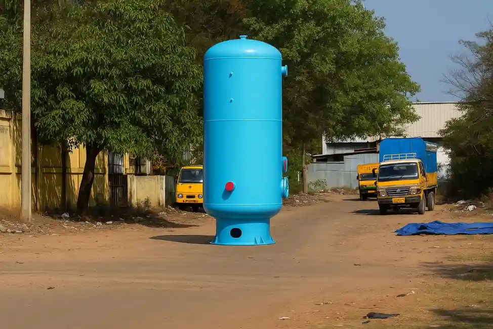
Minimum floor footprint — the standard industrial configurationCylindrical shell with dished heads oriented with its axis vertical. The standard configuration for stationary installations where floor space is at a premium and ceiling height is available. The vertical orientation also encourages moisture to settle to the bottom drain point by gravity — the natural direction of condensate movement in a standing vessel.
- Smallest floor footprint for a given volume — essential in compressor rooms, plant rooms, and machinery spaces
- Gravity aids condensate collection and drainage — the drain connection at the bottom collects all condensate efficiently
- Available in leg-support and ring-base configurations depending on floor loading and inspection access requirements
- Standard configuration for all sizes from 100 litres to 50,000 litres in stationary industrial service
- Pressure gauge, safety relief valve, inlet, outlet, and drain connections all positioned to API and ASME conventional layout
Horizontal Air Receiver
Low headroom installations — skid-mounted and mobile systemsCylindrical shell with dished heads oriented horizontally on saddle supports. Specified when ceiling height prevents vertical installation, when the receiver must be integrated into a low-profile compressor skid, or when the installation is mobile — portable compressor packages, truck-mounted compressed air systems, or trailer-mounted pneumatic supply units.
- Fits low-ceiling machinery rooms, under-platform installations, and skid packages with strict height envelopes
- Standard for compressor package skid integration — skid manufacturer specifies horizontal layout for transport stability and compact footprint
- Saddle supports allow precise elevation alignment with compressor and aftercooler discharge nozzles
- Drain must be positioned at the true low point of the shell — requires consideration of saddle position and shell orientation during installation
- Available for mobile service with reinforced saddles, transport tie-down provisions, and impact-rated nozzle connections
Pump-Mount Air Receiver
Compressor mounted directly on top — compact workshop and OEM packagesA vertical receiver with a reinforced flat top plate designed to support the weight of a piston compressor and motor directly on the vessel. Eliminates the separate compressor baseframe and minimises the total footprint of the compressor package. Standard configuration for workshop compressors, portable industrial units, and OEM compressor packages requiring a single integrated assembly.
- Flat top rated for compressor and motor static weight plus dynamic load from compressor vibration — structural design verified against fatigue
- Smallest total compressor package footprint — compressor, motor, and receiver occupy a single footprint equal to the vessel diameter
- Standard sizes from 100 to 500 litres with rated working pressures of 8 to 16 bar for workshop service
- Not suitable for large high-pressure compressors — vibration transmission through the vessel structure limits this configuration to smaller piston units
- Widely used by compressor OEMs as the standard delivery format for reciprocating compressor packages below 30 kW
High-Pressure Air Receiver
Above 16 bar — breathing air, instrument air, and specialty gas serviceDesigned and manufactured to ASME Section VIII for operating pressures from 16 bar to 350 bar. Used in breathing air systems, fire suppression nitrogen storage, high-pressure instrument air, CNG (compressed natural gas) buffer storage, and specialty industrial gas accumulation. Heavier wall thickness, higher-class flanges, and more rigorous weld inspection reflect the elevated stored energy hazard.
- Wall thickness calculated to ASME UG-27 for the specified design pressure — no standard catalogue vessel serves this range safely
- Full radiographic examination (RT) of longitudinal and circumferential welds mandatory at design pressures above 50 bar
- Post-weld heat treatment (PWHT) required for carbon steel vessels above specified wall thickness thresholds per ASME UCS-56
- Hydrostatic test at 1.5× MAWP witnessed by Third Party Inspection agency — test certificate issued and retained in the documentation package
- Safety relief valve capacity calculated to prevent pressure rising more than 10% or 3 psi above MAWP per ASME UG-125
Key Components Explained
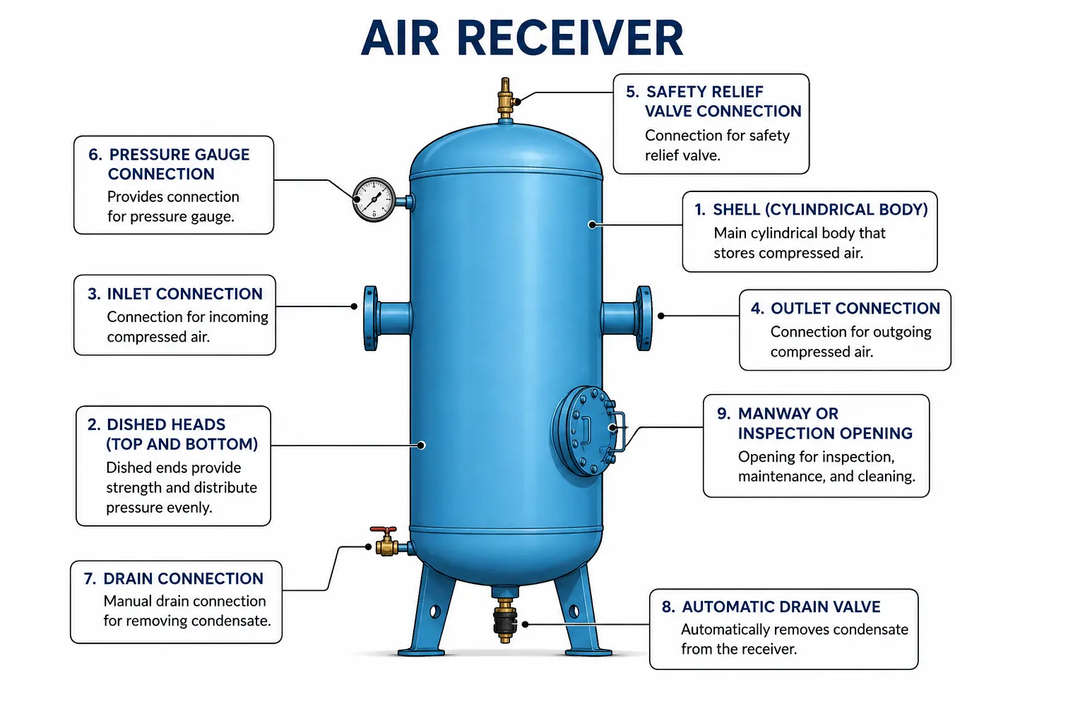
Shell (Cylindrical Body)
The main pressure-retaining cylindrical section of the vessel. Shell diameter and wall thickness are calculated to ASME UG-27 based on design pressure, design temperature, material allowable stress, and weld efficiency. For standard industrial receivers, SA-516 Grade 70 carbon steel plate is the most common material — offering excellent weldability, toughness at ambient temperature, and favourable cost at the volumes used in air receiver construction.
Dished Heads (Top and Bottom)
Formed end closures at each end of the cylindrical shell. Standard geometry is 2:1 semi-ellipsoidal — the most efficient head shape for pressure containment at standard industrial pressures. Hemispherical heads are used for very high-pressure receivers where their superior pressure efficiency justifies the deeper forming depth and higher cost. Head material matches the shell and is welded with full penetration butt joints examined to the applicable code category.
Inlet Connection
The flanged or threaded nozzle through which compressed air enters from the aftercooler or compressor discharge. Inlet nozzle is positioned to direct incoming air flow away from the outlet — preventing short-circuiting of air across the vessel without filling the storage volume. On wet receivers, the inlet is often baffled or directed tangentially to promote moisture separation by centrifugal action and reduce carry-over into the vessel outlet stream.
Outlet Connection
The nozzle through which stored compressed air exits to the distribution header, dryer, or point of use. Positioned to maximise the air path length through the receiver — typically at the top of a vertical vessel, diametrically opposite and elevated relative to the inlet. This configuration maximizes the effectiveness of pulsation damping and moisture separation by requiring stored air to pass through the entire vessel volume before exiting.
Safety Relief Valve Connection
A dedicated nozzle — sized and positioned per ASME UG-125 — through which the mandatory pressure relief device is installed. In the worst-case supply scenario, the relief valve must have enough releasing capacity to keep vessel pressure from surpassing MAWP by more than 10%, or 3 psi. The connection nozzle is never used for any purpose other than the safety relief device — no isolation valve is permitted between the nozzle and the relief valve.
Pressure Gauge Connection
A small-bore nozzle, typically ½ inch NPT or flanged, on the shell or head for the local pressure indicating gauge. The gauge displays vessel operating pressure for operator monitoring and safety compliance. A gauge isolation valve allows gauge removal for calibration or replacement without system depressurisation. Gauge range is selected for the design pressure — typically 1.5 to 2× MAWP for clear readability at normal operating pressure.
Drain Connection and Automatic Drain Valve
A bottom nozzle at the lowest point of the vessel shell or bottom head for condensate removal. On wet receivers, an automatic timed drain valve or a zero-loss demand-sensing drain valve continuously expels condensed moisture without manual intervention. Manual drain valves are acceptable only for receivers drained during planned shutdowns — they are inadequate for wet receivers in humid climates where condensate accumulates continuously during operation.
Manway or Inspection Opening
ASME code requires inspection access for all vessels above 36 inches in diameter — a 12-inch × 16-inch manway minimum. Instead, two 2-inch plugged inspection ports must be present in vessels 36 inches and smaller. The manway or inspection openings allow internal visual inspection for corrosion, pitting, deposit accumulation, and weld condition during scheduled pressure vessel inspections — typically every five years under statutory pressure vessel inspection regulations in India.
How to Size an Air Receiver: Formulas and Rules
Undersizing an air receiver is the most common and most costly compressed air system design error. An undersized receiver forces the compressor to cycle more frequently than its design allows — shortening valve life, increasing bearing wear, and raising energy consumption. The correct receiver size is a calculated engineering decision, not a catalogue pick.
Primary Receiver Sizing — The Rule of Thumb
For most fixed-speed compressor applications, the widely accepted industry starting point is 3 to 5 gallons of receiver volume per CFM of compressor output. A 200 CFM fixed-speed compressor therefore requires a primary receiver of 600 to 1,000 gallons minimum. For variable-speed drive compressors, the rule adjusts to 2 to 4 gallons per CFM — the VSD's ability to modulate output reduces the buffer requirement compared to a fixed-speed machine that can only be fully on or fully off.
💡 Wet-to-dry storage ratio: Best practice for total system storage is approximately one-third wet receiver capacity and two-thirds dry receiver capacity. If the total designed storage is 1,500 gallons, plan for 500 gallons before the dryer (wet) and 1,000 gallons after the dryer (dry). The larger dry storage ensures the dryer is never overloaded by demand surges drawing untreated air from the wet side.
Primary Receiver Sizing — Engineering Formula
When the demand event timing is known — for example, a pneumatic press that requires 500 CFM for 15 seconds every 2 minutes — the receiver can be sized precisely using the volume equation:
Secondary (Point-of-Use) Receiver Sizing
Secondary receivers at points of high intermittent demand are sized to supply the peak demand event without system pressure falling below the minimum acceptable level at that use point, before the distribution header can resupply the local tank. The same volume formula applies, but T, C, P1, and P2 are the local parameters — the event duration, local demand, starting pressure, and minimum acceptable pressure at that specific machine or process.
💡 The recharge formula: After a demand event draws down the receiver, the compressor must recharge it before the next event. Recharge time = (V × (P1 − P2)) ÷ (Pa × (Cr − C)) — where Cr is the compressor output in CFM and C is the continuing plant demand. If recharge time exceeds the interval between events, the system needs a larger receiver or a higher-capacity compressor. Getting this calculation right before procurement avoids the expensive retrofit of adding a second receiver vessel after system commissioning.
Design Specifications and Standards
| Parameter | Range / Options |
|---|---|
| Orientation | Vertical (standard) or horizontal — both available in all sizes |
| Capacity | 50 litres to 50,000 litres (standard); larger volumes on request as welded multi-shell assemblies |
| Design Pressure (MAWP) | 7 bar to 16 bar for standard industrial service; up to 350 bar for high-pressure specialty applications |
| Design Temperature | −20°C to +200°C depending on shell material and service conditions |
| Shell Material | SA-516 Gr. 70 carbon steel (standard); SA-240 304/316L stainless steel; SA-240 duplex 2205 on request |
| Head Type | 2:1 semi-ellipsoidal standard; hemispherical for high-pressure service above 50 bar |
| Nozzle Connections | ANSI flanged or NPT threaded — class selected per design pressure; minimum: inlet, outlet, safety relief, pressure gauge, drain, inspection opening |
| Surface Finish | Internal: shot blasted to Sa 2.5 + epoxy coating for moisture resistance; External: two-coat primer + polyurethane topcoat standard; hot-dip galvanised on request |
| Support | Vertical: saddle ring base or leg support; Horizontal: two carbon steel saddles with anchor bolt provisions |
| Weld Examination | Visual + radiographic (RT) for Category A and B welds; 100% RT for high-pressure service and stainless construction |
| Hydrostatic Test | 1.5× MAWP for a minimum of 30 minutes — witnessed by Third Party Inspection agency; certificate issued |
| Design Code | ASME BPVC Section VIII, Division 1 (U-Stamp and UM-Stamp); IS 2825 where specified; PED 2014/68/EU for export to European jurisdictions |
| Inspection Stamp | ASME U-Stamp (above 1 cubic foot internal volume, above 15 psi design pressure) or UM-Stamp for miniature vessels |
| Documentation | Manufacturer's Data Report (MDR), National Board registration, MTRs, hydrostatic test certificate, nameplate |
Material Selection Guide
Shell material selection for an air receiver is primarily driven by the moisture content and contamination risk of the stored compressed air, the operating temperature, the required service life, and whether the vessel will be used for general compressed air or a specialty gas service.
SA-516 Grade 70 Carbon Steel
The standard material for the overwhelming majority of industrial air receivers. Excellent weldability, well-characterised mechanical properties, wide availability of plate and formed heads, and cost-effectiveness make it the default choice for dry compressed air service where internal moisture is controlled by the drying system. Internal epoxy coating is applied on all carbon steel wet receivers to protect the shell from condensate-induced corrosion between drain cycles.
304 Stainless Steel (SA-240)
Specified when the stored compressed air contains moisture that the drainage and drying system cannot reliably eliminate — food-grade compressed air systems where contamination from internal corrosion products is unacceptable, pharmaceutical clean-room applications, and any service where the air contacts product directly. No internal coating required — the passive chromium oxide layer resists moisture corrosion without additional surface treatment.
316L Stainless Steel (SA-240)
Specified when the compressed air contains traces of chlorides — coastal installations where salt aerosols contaminate the inlet air stream, chemical plant service where process fugitive emissions contaminate ambient air, or food and beverage applications in cleaning-in-place (CIP) environments where chloride-containing sanitising agents contact vessel surfaces. The additional molybdenum content of 316L resists chloride pitting that 304 cannot tolerate.
Hot-Dip Galvanised Carbon Steel
An economical alternative to stainless for outdoor installations in moderately corrosive atmospheres. The zinc coating provides sacrificial protection to the carbon steel shell — extending external service life in tropical humid climates without the cost premium of stainless construction. Internal coating still required for wet receivers. Galvanising is applied after fabrication and before nozzle connection installation to ensure full coverage of all external welded surfaces.
SA-516 Gr. 60 Low-Temperature Carbon Steel
Specified for outdoor installations in cold climates where the receiver may be exposed to sub-zero ambient temperatures — cold-region mining, LNG facility compressed air systems, or offshore installations in northern latitudes. SA-516 Gr. 60 maintains adequate impact toughness at temperatures to −29°C. Charpy impact testing at the minimum design temperature is part of the material certification package for this specification.
Duplex Stainless (SA-240 UNS S31803)
Reserved for offshore and marine service where both internal moisture and external salt spray represent simultaneous corrosion risks. Duplex offers approximately double the yield strength of austenitic stainless — allowing thinner wall and lower vessel weight at the same pressure rating — while maintaining superior chloride corrosion resistance. The higher capital cost is justified by the operating environment and the cost consequence of replacing a failed offshore pressure vessel.
Industries and Applications
| Application | Receiver Role | Key Specification Driver |
|---|---|---|
| General Manufacturing — Pneumatic Tools | Primary wet receiver buffers compressor discharge; secondary dry receivers at tool stations supply peak demand during simultaneous multi-tool operation | Volume sized for peak simultaneous tool demand; carbon steel with internal coating; standard 7–10 bar design pressure |
| Automotive Assembly and Paint Shop | Dry receiver at painting station maintains stable air supply pressure during spray gun operation — preventing pressure fluctuation that causes paint film thickness variation and rework | Dry receiver after filtration to ISO 8573-1 Class 1; stainless or coated carbon steel to prevent contamination of painted surfaces from particulate or rust |
| Food and Beverage Processing | Stores instrument-quality compressed air for pneumatic actuators, product conveyance, and packaging — air contacts product directly in some applications | 304 or 316L stainless steel shell; no internal coating; electropolished internal surface for hygienic compliance; documented material traceability |
| Pharmaceutical Manufacturing | Clean dry air buffer for cleanroom pneumatics, lyophiliser loading systems, and filling line actuators — zero tolerance for particulate or moisture contamination | 316L stainless; electropolished to Ra ≤0.8 μm internal surface; passivated post-fabrication; IQ/OQ documentation package for validation |
| Oil and Gas — Instrument Air | Instrument air receiver buffers supply to safety instrumented systems (SIS), pneumatic control valves, and emergency shutdown actuators — must maintain minimum pressure for defined hold-up time during compressor trip | Hold-up time calculation determines volume; carbon steel or stainless per process area classification; ASME U-Stamp mandatory; SIL assessment may apply |
| Power Generation — Service Air | Service air receiver for turbine and generator maintenance tools, pneumatic hoists, cleaning lances — large intermittent demands from maintenance activities during planned outages | Large-volume horizontal receiver for plant room integration; carbon steel; rated for station design pressure; ring main distribution connection |
| Textile Mills | High-volume air receiver supplies air-jet looms — where compressed air is the weft-insertion mechanism. Looms operate at very high cycle rates, creating rapid, repetitive demand pulses | Large dry receiver close to loom bank; sized for simultaneous loom demand at design weaving speed; carbon steel standard; automated drain essential in humid mill environments |
| Construction and Infrastructure | Portable horizontal receiver on compressor trailer supplies jackhammers, rock drills, and concrete breakers — mobile service with vibration and transport loading | Horizontal orientation; reinforced saddles for transport; carbon steel; impact-rated nozzle connections; transport tie-down provisions; DOT or equivalent mobile certification |
ASME Certified Air Receivers — Sized, Certified, Delivered On Time
Vertical or horizontal, wet or dry, standard or high-pressure — every air receiver is ASME U-Stamp certified, hydraulically tested, and supplied with complete documentation. Free engineering proposal in 48 hours.
Request My Free Quote →How to Select the Right Air Receiver
Five engineering questions determine the correct air receiver type, size, orientation, material, and pressure class for a given installation. Working through them before issuing a purchase enquiry avoids costly misspecification.
Where in the System Does the Receiver Sit?
Before the dryer: specify a wet receiver — carbon steel with internal epoxy coating, automatic drain valve, inlet baffle for moisture separation. After the dryer: specify a dry receiver — stainless or coated carbon steel, no automatic drain required at design dew point. At a point of use for intermittent demand: specify a secondary dry receiver sized for the local demand event duration and volume. Position determines function; function determines configuration.
What Volume Is Required?
Apply the 3–5 gallons per CFM rule for a primary receiver starting point, then verify with the volume formula using your actual demand event profile. Undersizing is false economy — a receiver that is 30% too small will cause the compressor to cycle 40–60% more frequently, shaving years from valve and bearing life. When in doubt, size up: receiver vessel cost is a small fraction of the compressor rebuild cost it prevents.
What Is the Design Pressure?
Set design pressure at least 10% above the compressor relief valve setting — ensuring the receiver is never the weakest link in the pressure chain. Standard industrial compressed air at 7–10 bar: specify 10–12 bar MAWP. High-pressure instrument air at 15 bar: specify 17–18 bar MAWP. Never specify design pressure equal to operating pressure — the safety margin is not optional; it is an ASME requirement reflected in the wall thickness calculation.
Vertical or Horizontal?
Vertical is the default choice: smaller floor footprint, better condensate drainage, and simpler nozzle layout. Horizontal when: ceiling height is limited, the receiver must integrate into a low-profile skid package, or the installation is mobile. For wet receivers, horizontal orientation requires particular attention to drain placement — the drain must be at the true lowest point of the installed vessel, accounting for any saddle elevation and piping arrangement.
What Shell Material Is Required?
Carbon steel with internal coating: standard for general industrial compressed air with functional drying and drainage. Stainless steel 304: food, pharma, and applications where air contacts product or internal corrosion products are unacceptable. Stainless steel 316L: coastal, marine, chemical plant, and CIP environments with chloride exposure. Duplex: offshore with simultaneous internal and external corrosion risk. Never under-specify material to save cost — internal corrosion in a wet receiver progresses invisibly until wall perforation and sudden loss of pressure containment.
System Benefits of a Properly Sized Air Receiver
Compressor Cycling Reduction
Every start-stop cycle of a reciprocating or screw compressor subjects valves, pistons, bearings, and the motor starter to a mechanical and electrical stress event. A correctly sized primary receiver reduces cycling frequency by 30 to 50%, proportionally extending time between valve replacements and major overhauls. The capital cost of the receiver is recovered through reduced maintenance expenditure — typically within two to three years in continuous industrial service.
Stable Pressure at the Point of Use
Pneumatic tools, actuators, and processes that require a stable supply pressure to operate correctly — spray guns, precision pneumatic clamps, air bearing spindles — perform consistently when a receiver buffers the supply. Without a receiver, pressure at the tool falls during use as the compressor response lags behind demand. That pressure drop reduces tool output, increases cycle time, and in pressure-sensitive processes, directly affects product quality and reject rates.
Improved Dryer Efficiency
A wet receiver before the dryer reduces the peak moisture load the dryer must handle during high-demand events. Without this buffer, a sudden surge in demand draws hot saturated air directly from the compressor discharge into the dryer — exceeding rated inlet conditions and causing dew point slip. With a wet receiver, the air entering the dryer has already shed a significant fraction of its moisture to the receiver drain, protecting the dryer from overload and maintaining outlet dew point at specification.
Energy Cost Reduction
A correctly sized receiver allows the system to operate at the lowest practical header pressure that meets all point-of-use requirements — because the receiver buffers transient demand events that would otherwise require the compressor to maintain a higher standing pressure as a hedge against response lag. Compressor energy consumption is reduced by about 7% when system pressure is lowered by 1 bar (14.5 psi). Across a large industrial compressed air system, this saving compounds into significant annual energy cost reduction.
Pulsation Damping
Reciprocating compressors inherently produce periodic pressure pulses — one per piston stroke — at frequencies that can excite resonance in distribution pipework and connected instrumentation. A receiver vessel's internal volume acts as an acoustic low-pass filter, attenuating high-frequency pressure oscillations before they propagate into the distribution header. Without this damping, pipework vibrates, instrument readings fluctuate, and pressure transducers in control loops receive noisy signals that degrade control performance.
Emergency Air Reserve
In instrument air applications for safety instrumented systems and emergency shutdown systems, the air receiver is sized to maintain minimum pressure to all actuators for a defined hold-up time — typically 15 to 30 minutes — following a compressor trip. This hold-up time allows operators to take corrective action or execute a controlled plant shutdown before actuators lose their operating medium. The receiver volume for instrument air hold-up is an engineered safety requirement, not a performance optimisation — it must be calculated and documented as part of the SIS design basis.
Why United Heat Exchangers
An air receiver is not a commodity tank. A vessel operating continuously at 10 bar with cycling pressure loads, internal moisture, and vibration from connected equipment demands precise wall thickness calculation, correct weld category assignment, proper material selection for the actual service environment, and rigorous hydrostatic testing — all traceable through a complete documentation package. A receiver that fails these requirements may be cheaper on the purchase order; it will not be cheaper over its service life or in the event of a failure.
ASME U-Stamp — Every Applicable Vessel
Every air receiver above the ASME threshold (1 cubic foot internal volume, above 15 psi design pressure) is U-Stamp certified. The Manufacturer's Data Report is signed by our ASME-authorised inspector and registered with the National Board — the standard expected by every statutory pressure vessel inspection authority in India and internationally.
Engineered Sizing — Not Catalogue Selection
We size every receiver to your actual compressor output, demand event profile, and minimum acceptable pressure — using the correct primary and secondary receiver volume formulas. You receive a sizing calculation sheet with every proposal, confirming the vessel volume is adequate for your specific system — not an approximation from a nearest-standard catalogue size.
Right Material for the Service
Carbon steel with internal coating for general service; stainless for food, pharma, and product-contact applications; 316L for chloride-contaminated environments; duplex for offshore. We assess your service conditions and specify the correct material — not the cheapest material that passes cursory inspection.
Hydrostatic Test — Witnessed and Certified
Every air receiver is hydraulically tested to 1.5× MAWP with the test witnessed by a Third Party Inspection agency. The test certificate, along with the pressure gauge calibration record used during the test, is issued as part of the documentation package — providing the evidence your statutory pressure vessel inspection authority requires at first registration.
All Sizes, All Pressures, One Supplier
From 100-litre workshop receivers at 8 bar to 50,000-litre industrial receivers at 16 bar to high-pressure specialty vessels at 200 bar — all manufactured under one quality system, one design code authority, and one supply contract. No need to qualify separate suppliers for different pressure classes within the same plant.
Replacement and Retrofit Capability
If your current receiver is undersized, corroded, or no longer carries valid statutory inspection certification, we manufacture a certified replacement vessel to the same or upgraded nozzle layout. Where the existing foundation and piping allow, we match the replacement vessel OD and nozzle elevations to minimise site modification cost — prioritising your shutdown window over our manufacturing convenience.
Delivery and What's Included
What's Included with Every Air Receiver Order
- Receiver sizing calculation sheet — volume verified against your compressor output, demand event profile, and minimum acceptable pressure using the primary receiver volume formula
- ASME U-Stamp Manufacturer's Data Report (MDR) — signed by the ASME-authorised inspector; registered with the National Board for all applicable vessels
- Material certifications (MTRs) — mill test reports for shell plate, head material, nozzle forgings, and all pressure-retaining components; traceable to heat and certificate number
- Weld examination records — visual examination reports and radiographic test (RT) films and interpretation records for all applicable weld categories
- Hydrostatic test certificate — vessel tested to 1.5× MAWP; test witnessed by Third Party Inspection agency; calibration certificate for test gauges included
- ASME nameplate photograph — photographic record of the stamped nameplate showing MAWP, design temperature, NB registration number, and U-Stamp impression
- Internal coating inspection report — Holiday test results, DFT (dry film thickness) measurements, and surface preparation standard compliance records for carbon steel wet receivers
- Installation and commissioning guide — foundation loading data, nozzle load limits, recommended piping support arrangements, drain valve type and sizing, safety relief valve capacity verification procedure
- Operation and maintenance manual — statutory inspection interval recommendations, condensate drain valve maintenance schedule, corrosion monitoring protocol, and repair welding restrictions
- Lifetime technical support — re-rating for changed operating conditions, replacement nameplate service for requalification, and performance troubleshooting throughout the vessel service life
Get a Free Air Receiver Quote in 48 Hours
Share your compressor output (CFM or m³/min), operating pressure, demand event profile, wet or dry position, orientation preference, shell material, and site location. Our engineering team sizes the receiver, selects the correct material, and delivers a complete technical and commercial proposal within 48 hours.
Request My Free Quote →Frequently Asked Questions
What is the difference between a wet air receiver and a dry air receiver?
A wet receiver is installed before the compressed air dryer. It stores untreated, saturated air directly from the compressor discharge — its primary additional function is allowing bulk moisture to condense and collect at the drain before the air stream reaches the dryer. A dry receiver is installed after the dryer and filtration equipment. It stores treated compressed air at the dew point delivered by the dryer — its function is purely buffer storage for demand events, with no moisture separation role. Most industrial systems benefit from both: one wet receiver before the dryer and one or more dry receivers after it, or at points of high intermittent use.
How much air receiver capacity does my system need?
The practical starting point for a fixed-speed compressor is 3 to 5 gallons of receiver volume per CFM of compressor output. A 150 CFM compressor requires a primary receiver of 450 to 750 gallons. For variable-speed drive compressors, the guidance is 2 to 4 gallons per CFM — the drive's ability to modulate output reduces the buffer requirement. These rules give an initial vessel size; the precise volume should be confirmed using the primary receiver sizing formula with your actual demand event duration and acceptable pressure drop limits.
Is ASME certification mandatory for air receiver tanks in India?
For industrial applications, ASME U-Stamp or equivalent IS 2825 certification is required for all pressure vessels above the statutory threshold. ASME is the most widely recognised and internationally accepted certification — accepted by all major inspection authorities in India and permitting export without re-certification to most international jurisdictions. Non-code vessels should never be used in industrial applications: they have not undergone the design calculation review, weld examination, and hydrostatic testing that ASME certification requires, and they cannot be legally registered with statutory inspection authorities.
How often does an air receiver tank need to be inspected?
Under the Indian Factories Act and the Pressure Vessels Rules applicable in most Indian states, registered pressure vessels must be inspected by a competent person at intervals not exceeding 48 months (4 years) for internal inspection and at regular external inspections in between. The precise interval depends on the state Factories Act rules and the vessel's service classification. The Manufacturer's Data Report and registration certificate establish the vessel's identity for these statutory inspections — which is why ASME documentation is not optional for any vessel intended for continuous industrial service.
What maintenance does an air receiver tank require?
Daily: verify automatic drain valve operation — a blocked drain on a wet receiver allows condensate to accumulate, progressively reducing effective storage volume and increasing internal corrosion rate. Weekly: visual check of pressure gauge reading at steady-state operating conditions. Monthly: inspect external shell for corrosion, paint condition, and any sign of weeping at nozzle joints or weld seams. Annually: calibrate the pressure gauge and verify the safety relief valve lifts and reseats correctly. Every four years or per the statutory interval: internal inspection by a competent inspector as required by the applicable Pressure Vessels Rules.
Can an existing air receiver be re-rated to a higher pressure?
Possibly — but only after a formal re-rating calculation by a qualified pressure vessel engineer confirms that the existing wall thickness, head geometry, and weld quality are adequate for the higher MAWP. The calculation must be performed to the original design code (ASME Section VIII or IS 2825). If the calculation supports the higher pressure, a new ASME nameplate is issued and the National Board registration is updated. If the existing wall thickness is insufficient for the higher pressure, the vessel cannot be re-rated and must be replaced. Never operate an air receiver above its stamped MAWP without formal re-rating — doing so is illegal and dangerous.
What causes air receiver corrosion and how is it prevented?
Internal corrosion in carbon steel wet receivers is caused by condensate accumulating at the bottom of the vessel — moisture that did not drain between automatic drain valve cycles, or that accumulated when the drain valve failed closed. Prevention requires: a reliable automatic drain valve with frequent cycle intervals, a functional aftercooler upstream reducing moisture load, internal epoxy coating on all carbon steel wet receivers, and periodic interior examination to evaluate the thickness of the shell wall and coating condition. External corrosion is prevented by intact paint systems — any breach in the external coating should be repaired promptly before atmospheric moisture attacks the underlying steel.
What is the delivery time for an air receiver from United Heat Exchangers?
Standard carbon steel vertical and horizontal receivers up to 5,000 litres at standard industrial pressures (up to 16 bar) deliver in 3 to 6 weeks from order confirmation and approved data sheet. Stainless steel receivers, large-volume vessels above 10,000 litres, and high-pressure specialty vessels above 16 bar typically deliver in 6 to 12 weeks. Emergency replacement vessels for compressor station shutdowns and plant turnarounds are assessed individually — expedited manufacturing schedules are available when lead time is the critical constraint.
Author: Senthil Kumar, Technical Director — United Heat Exchangers Pvt. Ltd. | Last Updated: May 2026