Author: Gowtham, Technical Director | Updated: March 2026 | Read time: 8 min
Table of Contents
What Is a Surface Condenser?
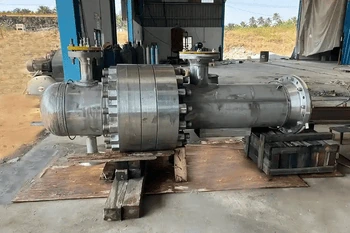
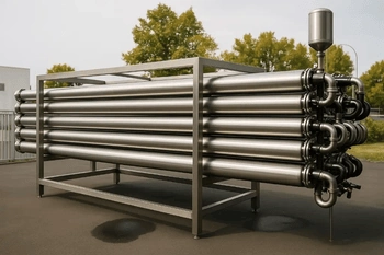
A surface condenser is a shell-and-tube heat exchanger that condenses exhaust steam from a steam turbine or process equipment on the shell side by rejecting heat to a cooling medium — typically cooling water or air — circulated through the tubes. Steam and cooling water never make contact; heat transfers entirely through the tube walls. This separation allows the condensate (high-purity distilled water) to be recovered, de-aerated, and returned directly to the boiler — recovering latent heat and dramatically improving steam cycle efficiency.
💡 Why vacuum matters: When steam condenses, its volume shrinks about 1,600 times, creating a vacuum in the condenser. This low back-pressure lets the turbine extract more energy from each kilogram of steam. Maintaining a strong 28–29 in Hg vacuum significantly improves plant efficiency.
How Does a Surface Condenser Work?
Exhaust steam from the turbine or process equipment enters the condenser shell through one or more large-diameter steam inlet nozzles at the top or sides. Inlet steam is at sub-atmospheric pressure — typically 0.05–0.15 bar absolute.
Cooling water (or other cooling medium) enters through the inlet water box, flows through the tube bundle at high velocity, and exits through the outlet water box. Tube-side velocity of 1.5–2.5 m/s is maintained to maximize the tube-side heat transfer coefficient and minimize fouling.
Condensation on Tube Outer Surface
Steam contacts the cold outer surface of the tubes and condenses into liquid water (condensate), releasing its latent heat of vaporization through the tube wall to the cooling water. The phase change from vapor to liquid is what generates and maintains the shell-side vacuum.
Liquid condensate falls by gravity into the hotwell — the sump at the base of the condenser shell. Condensate extraction pumps draw condensate continuously from the hotwell and deliver it to the deaerator or boiler feed system at the required pressure and temperature.
Air and other non-condensable gases that enter with steam or leak into the vacuum shell are concentrated in a dedicated air-cooled section of the tube bundle. Steam ejectors or liquid ring vacuum pumps continuously extract these gases to maintain design vacuum.
As long as cooling water flow rate is maintained and non-condensables are continuously removed, the shell pressure remains far below atmospheric — sustaining the turbine exhaust back-pressure that maximizes turbine output and cycle efficiency.
Types of Surface Condensers
Surface condensers are classified by orientation, steam admission configuration, and pass arrangement. The correct type is selected based on turbine exhaust geometry, site footprint, and cooling water availability.
Horizontal — Steam Down-Flow (Most Common)
Steam enters at the top of a horizontal shell and flows downward through the tube bundle to the hotwell at the base. The most widely used configuration in power plants — natural drainage of condensate, simple hotwell design, and easy air extraction from the lower pressure zones.
- Preferred for large utility and industrial steam turbines
- Direct connection to turbine exhaust flange below the LP casing
- Best condensate sub-cooling control
Horizontal — Central-Flow (Regenerative)
Steam enters from both sides of the shell and flows toward the center of the tube bundle. Non-condensables concentrate in the center air-cooling zone surrounded by condensing steam — improving air extraction efficiency and reducing re-evaporation losses.
- Better thermal performance than down-flow in large units
- Improved air removal — lower dissolved oxygen in condensate
- Preferred for high-efficiency power stations
Horizontal — Inverted / Up-Flow
Steam enters at the bottom of the shell and flows upward through the tube bundle. Used where turbine exhaust is directed upward and space constraints prevent a conventional below-turbine installation.
- Suitable for back-pressure retrofits with limited headroom
- Requires careful condensate drainage design to prevent flooding
Vertical Shell — Evaporator / Process Condenser
Shell axis is vertical — steam enters at the top, condensate drains by gravity from the bottom tube sheet. Used in process industries where a compact footprint is critical and where the steam load is moderate (process condensers, solvent recovery, pharmaceutical).
- Minimal plot area — ideal for plant retrofits
- Natural condensate drainage without extraction pump head concerns
- Common in pharmaceutical, fine chemical, and food-grade applications
Multi-Pass Water-Box (Two-Pass or Four-Pass)
Cooling water makes two or more passes through the tube bundle before exiting. Increases cooling water outlet temperature rise per pass — reduces cooling water flow requirement at the cost of higher tube-side pressure drop. Common in water-scarce locations or where pumping capacity is limited.
- Reduces cooling water flow demand — important for water-scarce sites
- Higher tube-side ΔT but increased pressure drop
- Divided water box with pass partition plate separates inlet and outlet
Key Components of a Surface Condenser
| Component | Function | Design Consideration |
|---|---|---|
| Shell | Encloses the tube bundle at sub-atmospheric (vacuum) operating pressure; contains the condensing steam and condensate. | Designed for full external pressure (vacuum) per ASME Section VIII. Typically carbon steel or stainless. Stiffening rings prevent shell collapse under vacuum. |
| Tube Bundle | Provides the heat transfer surface — cooling water flows through tube interiors; steam condenses on the outer tube surface. | Tube material selected for cooling water corrosivity. Tube pitch, layout, and bundle geometry optimized per HEI Standards for condensation heat transfer. |
| Tube Sheets | Hold all tube ends in position; separate the steam-side shell from the water-box cooling water circuit. | Must be compatible with both shell-side (steam/condensate) and tube-side (cooling water) fluid. Weld overlay applied when dissimilar metals are used. |
| Water Boxes | Distribute cooling water to the tube inlets and collect it from tube outlets. Divided water boxes serve multi-pass arrangements. | Sized for low pressure drop and even flow distribution. Rubber-lined or coated carbon steel is common for seawater service; titanium-clad for aggressive cooling water. |
| Hotwell | Collects and stores condensate at the bottom of the shell. Level-controlled by condensate extraction pumps. | Sized for adequate surge volume between pump starts. Hotwell temperature determines condensate sub-cooling — excessive sub-cooling wastes latent heat recovery. |
| Air Cooling Zone (ACZ) | Dedicated baffle-enclosed section of the tube bundle where non-condensable gases accumulate and are cooled before extraction. | HEI Standards specify minimum ACZ tube count. Proper ACZ design prevents air blanketing of the main tube bundle — a leading cause of vacuum loss and performance degradation. |
| Expansion Bellows | Flexible joint between turbine exhaust flange and condenser steam inlet — absorbs differential thermal expansion between the hot turbine casing and the cool condenser shell. | Designed per EJMA standards. Critical for protecting turbine exhaust flange from thermal stress — must be reviewed for fatigue life at startup/shutdown cycle rates. |
| Tube Support Plates / Baffles | Support tubes against sagging, vibration, and flow-induced oscillation along the bundle length. | Spacing governed by tube diameter, material, and unsupported span limits per HEI and TEMA. Flow-induced vibration (FIV) analysis mandatory for large condensers. |
Advantages of Surface Condensers
Steam and cooling water never mix — condensate exits at near-distilled-water purity (conductivity <0.1 µS/cm). This eliminates the need for make-up water treatment chemicals and allows direct boiler feedwater return, reducing operating costs significantly.
By maintaining 28–29 in Hg vacuum at the turbine exhaust, a well-designed surface condenser increases turbine enthalpy drop and output by 15–25% compared to atmospheric exhaust — the single largest thermodynamic improvement available to a steam cycle.
With correct tube material selection — admiralty brass, Cu-Ni, titanium, or stainless — surface condensers handle fresh water, brackish water, seawater, and recirculated cooling tower water across the full range of industrial cooling sources.
The large-diameter shell and generous steam inlet area accommodate the enormous specific volume of exhaust steam at vacuum conditions — a 1 kg/s steam flow at 0.07 bar abs occupies ~20 m³/s of volume before condensation.
Down-flow, central-flow, inverted, and vertical orientations; single or multi-pass water boxes; single or multi-shell arrangements — surface condensers adapt to virtually any turbine exhaust geometry, plot constraint, or cooling water availability.
Correct tube material selection and periodic chemical or mechanical tube cleaning gives surface condensers a 25–40 year operating life in power and process plant service — with tube-side cleaning accessed through removable water box covers without shell opening.
Surface Condenser vs. Jet Condenser
| Attribute | Surface Condenser | Jet (Barometric) Condenser |
|---|---|---|
| Steam/Water Contact | No — separated by tube walls | Yes — direct mixing |
| Condensate Recovery | Yes — high-purity boiler feedwater | No — contaminated, cannot be reused |
| Operating Vacuum | Deep — 28–29 in Hg achievable | Limited — governed by cooling water temperature |
| Turbine Efficiency | Highest — maximum enthalpy drop | Lower — higher back pressure |
| Capital Cost | Higher — shell-and-tube construction | Lower — simple mixing chamber |
| Cooling Water Consumption | Recirculated — lower consumption | Once-through — high water consumption |
| Applicable Service | Power generation, process, pharma, refinery — any high-value steam cycle | Low-value process applications where condensate reuse is not required |
| Best For | All steam turbine and high-value process condensing duty | Low-duty, once-through process condensing where water cost is negligible |
Not Sure Which Condenser Type Fits Your Application?
Our engineering team reviews your turbine exhaust conditions, cooling water source, condensate recovery requirements, and site constraints — and recommends the optimal surface condenser configuration with full HEI and ASME analysis. Free consultation, no obligation.
Talk to Our Engineers →Key Design Parameters
| Parameter | Typical Range | Engineering Significance |
|---|---|---|
| Turbine Exhaust Pressure | 0.05–0.15 bar abs (1.5–4.5 in Hg abs) | Sets the saturation temperature of condensing steam and directly determines cooling water inlet temperature requirements and tube surface area needed. |
| Steam Load (Heat Duty) | 1 MW – 1,000+ MW thermal | Determines required condensing surface area (m²). HEI heat transfer rates (BTU/hr·ft²·°F) are used for surface sizing based on tube material and cooling water velocity. |
| Cooling Water Inlet Temperature | 15°C – 35°C (typical) | The single biggest factor governing achievable vacuum. Colder cooling water = deeper vacuum = higher turbine efficiency. Terminal temperature difference (TTD) between steam saturation temp and CW outlet is 2–6°C in well-designed units. |
| Cooling Water Velocity | 1.5–2.5 m/s (5–8 ft/s) | Higher velocity improves tube-side heat transfer coefficient and reduces fouling; excessive velocity causes tube erosion (especially in copper alloys). HEI specifies maximum velocities by tube material. |
| Tube OD & Wall Thickness | ¾ in, 1 in OD; 18–22 BWG wall | ¾ in tubes give more surface per shell volume; 1 in tubes are easier to clean and resist erosion at higher velocities. Wall thickness per HEI minimum — governed by tube material and cooling water corrosivity. |
| HEI Cleanliness Factor | 75–85% (typical design basis) | HEI defines the cleanliness factor as the ratio of fouled to clean heat transfer coefficient. Design at 85% for clean fresh water; 75% for cooling tower or brackish water. Lower factors require more tube surface area. |
| Air Inleakage Allowance | Per HEI Table — function of steam load | HEI Standards specify maximum allowable air inleakage by condenser heat duty. Vacuum pump or steam ejector must be sized to handle this load plus a design margin without allowing vacuum degradation. |
| Condensate Sub-Cooling | <3°C below saturation (target) | Excessive condensate sub-cooling (hotwell temperature well below steam saturation temperature) wastes latent heat and increases dissolved oxygen — both detrimental to cycle efficiency and boiler feed quality. |
Design tip: Always specify the HEI cleanliness factor on the datasheet — not just the clean overall heat transfer coefficient. A condenser sized only for clean conditions will fail to maintain design vacuum within weeks of commissioning as tube-side fouling deposits build up.
Materials of Construction
| Component | Common Material | ASME / Standard Grade | Cooling Water Service |
|---|---|---|---|
| Shell | Carbon steel plate | SA-516 Gr. 60/70 | All services — external pressure (vacuum) design per ASME Sec. VIII Div. 1 |
| Shell | 304L / 316L stainless | SA-240 TP304L / TP316L | Pharmaceutical, food-grade, process condensers with aggressive steam-side chemistry |
| Tubes | Admiralty brass | ASTM B111 C44300 | Clean fresh water / cooling tower water — low chloride |
| Tubes | Copper-nickel 90/10 | ASTM B111 C70600 | Brackish water, low-salinity seawater, coastal cooling |
| Tubes | Copper-nickel 70/30 | ASTM B111 C71500 | Higher-salinity seawater, offshore service |
| Tubes | Titanium Grade 2 | ASTM B338 | Seawater cooling, high-chloride, aggressive oxidizing cooling water |
| Tubes | 316L stainless steel | SA-213 TP316L | Process condensers, pharmaceutical, clean demineralized water circuits |
| Tubes | Carbon steel SA-179 | ASME SA-179 | Clean fresh water / deionized water — low-corrosion utility service only |
| Water Boxes | Carbon steel (rubber-lined) | SA-516 | Seawater and aggressive cooling water — rubber lining prevents corrosion |
| Water Boxes | Cast iron / ductile iron | ASTM A48 / A536 | Fresh water and low-corrosion cooling tower water |
| Tube Sheets | Naval brass / Muntz metal | ASTM B171 | Standard with copper-alloy tubes — compatible for tube rolling and welding |
| Tube Sheets | Carbon steel + titanium cladding | SA-516 + ASTM B265 | Titanium tube installations — clad face prevents galvanic coupling |
⚠ Seawater tube material selection: Never specify admiralty brass or carbon steel tubes in seawater service. Chloride-induced pitting and erosion-corrosion will cause premature tube failure — typically within 2–5 years. Specify copper-nickel 90/10 as the minimum for brackish water and titanium Grade 2 for direct seawater service.
Industrial Applications
| Industry | Application | Steam Source | Cooling Medium |
|---|---|---|---|
| Thermal Power Generation | Main turbine exhaust condenser — the largest surface condenser application worldwide | LP turbine exhaust | Cooling tower water, river water, seawater |
| Nuclear Power | Main condenser — requires titanium or stainless tubes for condensate purity compliance | LP turbine exhaust | River water or seawater (once-through) |
| Captive Power / Cogeneration | Back-pressure or condensing turbine exhaust for industrial captive power plants | Industrial steam turbine exhaust | Cooling tower water |
| Oil Refining & Petrochemical | Process condenser for steam strippers, vacuum distillation overhead, and steam ejector condensers | Process steam / ejector steam | Cooling water |
| Chemical Processing | Solvent condenser, reactor vent condenser, vacuum system condenser | Solvent vapor / steam | Cooling water or chilled water |
| Pharmaceutical Manufacturing | Pure steam condenser, WFI still condenser — strict condensate purity requirements | Pure steam / WFI vapor | Chilled water; 316L SS tubes mandatory |
| Sugar & Distillery | Multiple-effect evaporator condenser, vapor condenser in sugar pans | Vapor from evaporators | Cooling tower water or river water |
| HVAC & Refrigeration | Steam-driven absorption chiller condenser, refrigerant condenser for large chiller plant | Refrigerant vapor / steam | Cooling tower water |
Surface Condensers for Power, Process & Industry
From 1 MW captive power condensers to large utility-scale units — United Heat Exchangers engineers and fabricates surface condensers to HEI Standards, ASME Section VIII, and TEMA Class R/B for clients across India, the US, Middle East, and internationally.
Request My Free Quote →Maintenance and Cleaning Best Practices
Tube-Side Cleaning (Mechanical Access via Water Box)
- Soft biological fouling / slime: High-pressure water lance through open water box after unbolting the water box cover. No shell opening required.
- Hard scale (calcium carbonate / sulfate): Mechanical tube brushing, pneumatically-driven tube cleaners, or chemical descale circulation through the tube circuit.
- Online automated cleaning: Sponge ball systems (TAPROGGE / Conco type) continuously circulate through tubes — virtually eliminate cooling-water-side fouling between scheduled outages. Standard practice on large power station condensers.
- Chlorination / biocide dosing: Continuous or shock-dose chlorination of cooling water inlet prevents biological growth inside tubes — mandatory for open cooling tower circuits.
Shell-Side Maintenance
- Shell side (steam/condensate) is generally clean — periodic visual inspection through manways for corrosion, tube bundle integrity, and baffle condition at each major outage.
- Check hotwell for sediment accumulation and clean if required — sediment indicates tube failures or condensate system contamination.
- Inspect steam inlet impingement plates and steam lane denisters for erosion damage from high-velocity wet steam or condensate droplet carryover.
Turnaround Inspection Checklist
- Eddy current testing (ECT) of all tubes through open water box — detects wall thinning, pitting, and cracking without opening the shell. Full-bundle survey every 2–4 years.
- Hydraulic pressure test of tube bundle after any tube plugging or retubing — confirm shell-to-tube leakage integrity before returning to service.
- Inspect expansion bellows between turbine exhaust flange and condenser steam inlet for corrosion, cracking, and fatigue — replace per EJMA cycle life rating.
- Replace all water box cover gaskets and manway gaskets at every outage opening — never re-use compression gaskets.
- Check vacuum system (ejectors or liquid ring pumps) for wear, nozzle erosion, and seal water condition — degraded vacuum equipment is the leading cause of condenser underperformance.
- Verify condensate level control valve, extraction pump minimum flow valve, and hotwell level transmitters are calibrated and functioning — hotwell flooding causes turbine exhaust back-pressure surge.
Standards and Codes
| Standard | Issuing Body | Application to Surface Condensers |
|---|---|---|
| HEI Standards for Steam Surface Condensers | Heat Exchange Institute (HEI) | Primary design standard — governs tube heat transfer rates, cleanliness factors, air inleakage allowances, tube material velocity limits, and hotwell sizing. Mandatory reference for all power station surface condensers. |
| ASME BPVC Section VIII Div. 1 & 2 | ASME | Pressure vessel construction of the shell, water boxes, tube sheets, and all pressure-containing components. Includes external pressure (vacuum) design per ASME UG-28 for shell collapse prevention. |
| TEMA Class R / B | TEMA | Shell-and-tube construction tolerances, minimum tube wall gauges, tube-to-tubesheet joint requirements, and baffle/support plate design practices. |
| EJMA Standards | Expansion Joint Manufacturers Association | Design, pressure rating, cycle life, and spring rate of the flexible bellows expansion joint at the turbine exhaust-to-condenser connection. |
| ASME B31.3 Process Piping | ASME | Condensate extraction piping, cooling water piping nozzle connections, and vacuum pump/ejector piping attached to the condenser. |
| NACE MR0175 / ISO 15156 | NACE / ISO | Material qualification for sour service environments — applicable when steam-side or cooling water-side may contain H₂S (refinery and gas plant process condensers). |
| PED 2014/68/EU | European Commission | Mandatory CE marking for surface condensers placed on the European market — full technical file and Notified Body review. |
| IS 2825 | Bureau of Indian Standards | Indian unfired pressure vessel code — available for domestic Indian projects requiring statutory BIS compliance. |
| ISO 9001:2015 | ISO | Quality management system governing all engineering, procurement, fabrication, inspection, testing, and documentation processes. |
Why Choose United Heat Exchangers?
- 35+ years of manufacturing experience — surface condensers supplied to power stations, captive power plants, refineries, chemical plants, pharmaceutical facilities, and sugar mills across India, the US, Middle East, Southeast Asia, and Europe.
- ASME U-Stamp and R-Stamp certified fabrication — complete code documentation package delivered with every unit for regulatory, insurance, and owner compliance requirements.
- HEI-compliant thermal design — all surface condensers sized using HEI Standards for Steam Surface Condensers, with cleanliness factor, air inleakage allowance, and condensate sub-cooling all explicitly addressed in the thermal design report.
- Full TEMA Class R and B capability — construction standard matched to service severity and project specification on every order.
- All condenser types available: Down-flow, central-flow, inverted, vertical, single-pass and multi-pass water-box — engineered and fabricated in-house under one quality system.
- Complete tube material range: Admiralty brass, Cu-Ni 90/10 and 70/30, titanium Grade 2, 304/316L stainless, and carbon steel — specified for your exact cooling water chemistry.
- In-house flow-induced vibration (FIV) analysis — mandatory for large steam condensers to prevent tube bundle failure from tube vibration at operating steam velocities.
- Expansion bellows — design and supply included — EJMA-compliant bellows engineered as part of the complete condenser assembly when required.
- Fast delivery: Standard units 4–8 weeks; large power station units and exotic alloy units 8–20 weeks.
- Lifetime technical support — OEM thermal performance documentation, maintenance guidance, and troubleshooting assistance available throughout the equipment service life.
- Free budgetary quote within 48 hours of receiving your steam load datasheet, cooling water analysis, and site conditions.
Frequently Asked Questions
1. What is a surface condenser and how does it work?
A surface condenser is a shell-and-tube heat exchanger that condenses exhaust steam on the shell side by rejecting heat to cooling water flowing through the tubes — without the two fluids ever mixing. Steam condensation collapses steam volume by ~1,600×, creating shell-side vacuum that allows the turbine to exhaust at sub-atmospheric pressure — increasing turbine output and recovering high-purity condensate for direct boiler return.
2. What is the difference between a surface condenser and a jet condenser?
In a surface condenser, steam and cooling water are physically separated by tube walls — condensate is recovered at near-distilled-water purity for boiler feedwater reuse. In a jet condenser, steam and cooling water mix directly — the condensate is contaminated and cannot be reused. Surface condensers deliver deeper vacuum, higher turbine efficiency, and condensate recovery; jet condensers are cheaper but waste water and cycle energy.
3. What vacuum level does a surface condenser achieve?
A well-designed and maintained surface condenser achieves 28–29 in Hg vacuum (710–735 mmHg, or 0.035–0.07 bar abs) at rated cooling water temperature. Vacuum level depends on cooling water inlet temperature, cooling water flow rate, tube cleanliness (HEI cleanliness factor), and the efficiency of the air extraction system (steam ejectors or liquid ring vacuum pumps).
4. Which tube material should I specify for my cooling water?
Select tube material based on cooling water chemistry: admiralty brass for clean low-chloride fresh water; copper-nickel 90/10 for brackish or moderately saline water; copper-nickel 70/30 or titanium Grade 2 for seawater service; 316L stainless for pharmaceutical or high-purity process condensate circuits. Never use admiralty brass or carbon steel in seawater — chloride pitting causes rapid failure.
5. What information do I need to request a surface condenser quote?
Provide: steam flow rate (kg/hr) and inlet pressure/temperature; cooling water inlet temperature and maximum allowable outlet temperature; cooling water source and analysis (TDS, chlorides, pH, hardness); allowable pressure drop (tube side and shell side); design code (ASME, HEI, TEMA class); applicable standards (API 660, PED, IS 2825); and installation orientation. Our engineers deliver HEI-compliant thermal sizing and budgetary pricing within 48 hours.
6. Are your surface condensers HEI and ASME certified?
Yes. All surface condensers are designed to HEI Standards for Steam Surface Condensers and fabricated per ASME BPVC Section VIII Division 1 or 2, with ASME U-Stamp certification. United Heat Exchangers holds current ASME U-Stamp and R-Stamp certifications and complies with TEMA Class R/B, EJMA, PED 2014/68/EU, IS 2825, and NACE MR0175 as required by each project specification.
Get Your Free Surface Condenser Quote in 48 Hours
Share your steam load, cooling water conditions, vacuum requirement, and applicable codes — and our thermal engineering team will size and configure the right surface condenser for your application, backed by 35+ years of HEI and ASME-certified manufacturing experience.
Request My Free Quote →Author: Senthil Kumar, Technical Director — United Heat Exchangers Pvt. Ltd. | Published: March 2026