Author: Senthil Kumar, Technical Director | Updated: June 2026
Table of Contents
- What Is a Finned Cooler?
- How a Finned Cooler Works — The Engineering Principle
- Types of Finned Coolers
- Finned Cooler Anatomy — Key Components
- Fin Types Explained — Plain, Serrated, Corrugated, Longitudinal
- Engineering Advantages of Finned Coolers
- Design Specifications and Standards
- Material Selection Guide — Tubes, Fins, Shell
- Industries and Applications
- Finned Cooler vs Bare Tube Heat Exchanger
- How to Select a Finned Cooler
- Maintenance and Cleaning Guide
- Why United Heat Exchangers
- Delivery and What's Included
- Frequently Asked Questions
What Is a Finned Cooler?
A finned cooler is a heat exchanger in which the external fins, which are thin metal projections attached to the outside of tubes, plates, or channels, are purposefully added to the primary heat transfer surface to increase the effective heat transfer area significantly above what the bare metal surface could give. The fundamental engineering challenge that finned coolers solve is the mismatch in heat transfer coefficients: a high-velocity liquid or pressurized gas inside a tube may have a convective heat transfer coefficient of 500–5,000 W/m²K, while the air or cooling fluid flowing outside the same tube in a conventional bare-tube design might have a coefficient of only 30–150 W/m²K. This tenfold to fiftyfold mismatch means the outside surface area becomes the bottleneck — and fins are the engineering solution that removes it.
By attaching fins to the tube exterior, a finned tube cooler increases the outer surface area by a factor of 5 to 25 times the bare tube surface — directly reducing the thermal resistance on the fin side and enabling the full heat transfer potential of the tube-side fluid to be realized in a compact, cost-effective unit. The result is a cooler that handles the same heat duty as a bare-tube exchanger many times its size — or handles a far greater duty in the same footprint — making finned coolers the default choice wherever air, low-velocity liquid, or viscous fluid is the cooling medium.
As a leading finned cooler manufacturer in India, United Heat Exchangers designs and fabricates air cooled finned coolers, liquid cooled finned coolers, shell and tube finned coolers, plate finned coolers, and custom extended-surface cooling solutions in aluminum, copper, stainless steel, carbon steel, and exotic alloys — for power generation, oil and gas, petrochemical, automotive, marine, and industrial process applications. Every finned cooler is thermally rated by HTRI, pressure-designed to ASME Section VIII, and supplied with full certification and documentation.
How a Finned Cooler Works — The Engineering Principle
Every heat exchanger is governed by the fundamental Fourier heat transfer equation: Q = U × A × ΔT_mean, where Q is the heat duty, U is the overall heat transfer coefficient, A is the heat transfer surface area, and ΔT_mean is the mean temperature difference between the two fluid streams. For a given heat duty and temperature difference, U and A are the engineer's two controllable variables. In a finned cooler, the design philosophy is clear: when the nature of one cooling fluid (air or low-velocity liquid) limits U to a low value, compensate by making A very large through fins.
Engineering Insight — Why Fins Matter More Than You Think: The overall heat transfer coefficient U is the reciprocal of the sum of all individual thermal resistances: 1/U = 1/h_i + r_wall + r_fouling + 1/h_o × (A_o/A_i), where h_i is the tube-side film coefficient, r_wall is the tube wall resistance, r_fouling is the fouling allowance, and h_o is the outer (fin-side) film coefficient. In a finned cooler with an air-side h_o of only 40 W/m²K and a tube-side h_i of 3,000 W/m²K, the air-side resistance dominates completely — accounting for over 90% of the total thermal resistance. The only engineering lever that directly reduces this dominant resistance without increasing fan power is the fin area: by making A_fin = 20× A_bare, the effective outer resistance is reduced by a factor of 20, transforming the design from air-side limited to a balanced configuration where tube-side and air-side resistances are comparable.
Hot Fluid Enters Finned Tubes
The process fluid — oil, gas, water, refrigerant, or any industrial fluid — enters the tube side at inlet temperature and pressure, flowing through the finned tube bundle.
Conduction Through Tube Wall
Heat conducts from the hot tube-side fluid through the tube wall. The tube metal's conductivity determines the wall resistance — copper and aluminum minimize it; steel is adequate for most services.
Conduction Up Through Fins
Heat spreads from the tube wall up through the fin metal. Fin efficiency (η_f) describes how effectively heat reaches the fin tip — taller fins have lower efficiency; aluminum and copper fins maximize it through high conductivity.
Convection from Fin Surface to Coolant
The cooling medium — air or liquid — flows across the large extended fin surface, absorbing heat by convection from the fin tips, fin flanks, and exposed bare tube segments between fins.
Cooled Fluid Exits
Process fluid exits the finned cooler at the required outlet temperature. The cooling medium exits at elevated temperature, carrying the absorbed heat to atmosphere (air cooled) or to a secondary cooling circuit (liquid cooled).
A critical concept unique to finned coolers is fin efficiency (η_f). Because the fin is attached at its base (the tube wall) and heat must conduct outward to the fin tip, there is a temperature gradient along the fin height — the fin tip is always cooler than the fin base. A fin of infinite thermal conductivity would have η_f = 1.0 (100% efficient — every part of the fin is at the same temperature as the tube wall). In practice, aluminum fins on typical air cooled finned cooler bundles have fin efficiencies of 0.85–0.95, while stainless steel fins — with much lower conductivity — may have efficiencies as low as 0.50–0.70, requiring more fin area to achieve the same heat transfer. This is why material selection for fins is as important as material selection for tubes in any finned cooler design.
Types of Finned Coolers
United Heat Exchangers manufactures all principal finned cooler configurations. The correct type is selected based on the cooling medium available, the process fluid properties, operating pressure, required outlet temperature, available plot space, and the service environment.
Air Cooled Finned Cooler (Fin Fan Cooler)
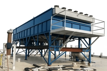
Ambient air over finned tube bundle — no cooling water requiredThe most widely installed category of finned cooler worldwide — a finned tube bundle through which the process fluid flows is exposed to a forced airstream driven by motor-driven axial flow fans. Aluminum fins on the tube outer surface multiply the air-side heat transfer area 15–25 times above the bare tube, compensating for air's low convective coefficient. Designed to API 661 for refinery and process service.
- No cooling water required — ambient air is the sole cooling medium, making it the default for water-scarce and remote locations
- Process fluid outlet temperature: approximately 8–15°C above design ambient dry-bulb temperature
- A fan configuration that induces draft (fan above bundle) or forces draft (fan below bundle)
- Auto-variable pitch fans for precise outlet temperature control across ambient temperature variation
- API 661 plug header or cover plate header — individual tube access for in-service maintenance
- Applications: compressor after coolers and inter coolers, gas processing coolers, refinery product coolers, power generation auxiliary coolers, lube oil coolers
Liquid Cooled Finned Cooler
Water, seawater, glycol, or oil — finned tube immersed in liquid coolantA liquid cooled finned cooler uses a liquid coolant — water, seawater, ethylene glycol, or oil — flowing over or through the outer fin surface to cool the process fluid inside the tubes. Fins are applied to the tube exterior to compensate for the relatively low heat transfer coefficient of the liquid on the outer surface, particularly when the outer liquid is viscous (oil) or flowing at low velocity. The finned surface dramatically increases the liquid-to-tube contact area without increasing the cooler's external dimensions.
- Liquid coolants: fresh water, seawater (copper-nickel finned tube), glycol solutions, hydraulic oil, transformer oil
- Fins on tube exterior compensate for low outer-surface film coefficient when liquid is viscous or at low velocity
- Achieves lower process outlet temperature than air cooled designs — coolant temperature typically 30–45°C
- Compact construction — higher coolant film coefficient enables smaller overall unit size than air cooled equivalent
- Applications: engine oil coolers, hydraulic oil coolers, transformer oil coolers, central cooling systems for marine and offshore
- Shell material matched to coolant chemistry — carbon steel for clean water, stainless for corrosive, Cu-Ni for seawater
Shell and Tube Finned Cooler
Finned tubes inside a pressure shell — high-pressure fluid-to-fluid serviceA shell and tube finned cooler assembles finned tubes inside a cylindrical pressure shell — the process fluid flows through the finned tubes (tube side) while the cooling fluid flows across the fin surfaces on the shell side, guided by segmental baffles. The fins enhance the shell-side heat transfer coefficient — particularly valuable when the shell-side fluid is a viscous oil, low-velocity gas, or a fluid with poor natural convective properties. TEMA-R, B, or C classification; ASME Section VIII pressure parts.
- Finned tubes enhance shell-side coefficient — critical when shell-side fluid is viscous, slow-moving, or gaseous
- Handles high pressures on both tube and shell sides — full ASME Section VIII design on all pressure-containing components
- TEMA classification: BEM, BEU, AEW, or BEW depending on fouling, cleaning, and thermal expansion requirements
- Tube configurations: U-tube (most common — accommodates thermal expansion), fixed tube sheet, floating head
- Applications: lube oil coolers in gas turbines and reciprocating engines, transformer oil coolers, hydraulic power pack coolers, high-viscosity process fluid coolers
- Longitudinal finned tubes (fins running along the tube axis) used on the shell side when shell-side flow is parallel to tube axis
Plate Finned Cooler
Corrugated fins between flat separator plates — maximum compactnessA plate finned cooler is a compact heat exchanger constructed by stacking layers of corrugated or louvred aluminum or stainless steel fin sheets between flat separator plates, brazed or bolted together to form a rigid block. Each fluid stream flows through alternating layers of fins, with the fin geometry optimized for each stream independently — corrugated, louvred, perforated, or serrated fins selected to maximize heat transfer with acceptable pressure drop for each fluid.
- Extremely compact — fin surface area density of 500–2,000 m²/m³, far exceeding shell-and-tube designs
- Multiple fluid streams can pass through a single unit — up to 10 streams in a multi-stream plate fin heat exchanger
- Aluminum construction standard for cryogenic and moderate temperature service; stainless for higher temperature and corrosive applications
- Low pressure drop on both sides — corrugated fin geometry optimized for balanced pressure drop across all streams
- Applications: air separation cryogenic coolers, LNG processing, natural gas dew point coolers, gas turbine air inlet chillers, hydraulic oil circuit coolers in mobile equipment
- Brazed aluminum plate fin heat exchangers (BAHX) are the industry standard for cryogenic and LNG applications
Economizer / Waste Heat Recovery Finned Cooler
Boiler economizer — helical fins on carbon steel tubes in flue gas streamAn economizer is a finned cooler positioned in the hot flue gas stream of a boiler, furnace, or gas turbine exhaust to recover waste heat and pre-heat boiler feed water or combustion air. Extended fins on the tube exterior dramatically increase the tube-to-gas contact area — compensating for the extremely low convective coefficient of flue gas — enabling efficient heat recovery from a stream that would be economically and thermally impossible to cool with bare tubes alone.
- Helical serrated fins on carbon steel or alloy tubes — high fin density (5–8 FPI) in clean flue gas; low fin density in fouling or soot-laden gas
- Design temperature: 200°C to 550°C for economizer service — embedded or extruded fins (not tension-wound) for service above 232°C
- Solid (plain) fins for clean gas; serrated fins for enhanced heat transfer in cleaner flue gas; bare tubes for very fouling or corrosive gas streams
- IBR approval for all economizers in steam-generating service in India
- Applications: boiler economizers, combined heat and power (CHP) exhaust gas coolers, gas turbine heat recovery steam generators (HRSG), diesel engine exhaust heat recovery
- Soot blowers specified for economizers in heavy fuel oil, coal, or waste-fired boiler service
Evaporative Finned Cooler (Hybrid Air/Water)
Evaporative assist — lower outlet temperature than dry air finned coolerAn evaporative finned cooler enhances air side performance by spraying a controlled water mist onto the finned tube bundle surfaces or into the incoming air stream — the evaporation of the water film cools the air approaching the fins well below the ambient dry-bulb temperature, towards the wet-bulb temperature. This allows the finned cooler to achieve process outlet temperatures 8–15°C lower than a dry air cooled unit at the same ambient conditions — critical for meeting tight outlet temperature specifications in hot summer conditions.
- Process outlet temperature approaches ambient wet-bulb rather than dry-bulb — 8–15°C lower outlet than dry unit at same ambient
- Valuable in hot Indian summer conditions (45–50°C dry-bulb) where dry finned coolers cannot meet outlet specification
- Water consumption 85–90% less than equivalent water-cooled shell-and-tube design
- Anti-scale water treatment and drift eliminators required — proper design prevents scale buildup on fin surfaces
- Applications: gas compression after coolers in hot climates, LNG auxiliary coolers, close-approach refinery product coolers
- Evaporative assist applied as a seasonal supplement to a base dry air cooled finned cooler unit
Finned Cooler Anatomy — Key Components

Finned Tubes
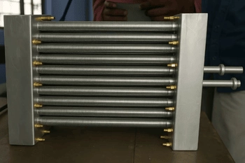
The heat transfer core — prime tubes in carbon steel, stainless, copper, or alloy, fitted with external fins in aluminum, copper, or steel. The finned tube dimensions — tube OD, wall thickness, fin height, fin pitch, fin thickness, and attachment method — are the primary design variables that determine the overall heat transfer coefficient, pressure drop, fouling tolerance, and cleanability of the finned cooler. Standard 1-inch OD × 9 FPI aluminum-finned tube to API 661 is the industry baseline.
Tube Headers
Box headers at each end of the tube bundle distribute the process fluid to all tubes and collect it after the required number of passes. API 661 defines four header types: plug header (Type B — individual tube access via threaded plugs, default for process service), cover plate header (Type A — removable bolted face for high-fouling service), welded bonnet (Type C — for high pressure or lethal service), and manifold/pipe and U-bend (Type D — for very high pressure). The header material is matched to the process fluid — carbon steel for hydrocarbons, 316L SS for corrosive service.
Axial Flow Fans and Drive
In Air cooled finned coolers use electric motors controlled by belt drives or gearboxes to propel large-diameter axial flow fans (2.5-5 m diameter) across the finned bundle. Fan coverage must be at least 40% of the bundle face area; bundle static pressure resistance must be at least 3.5 times the fan ring velocity pressure to ensure uniform air distribution. Auto-variable pitch fans adjust blade angle continuously to maintain process outlet temperature across seasonal ambient variation.
Plenum Chamber
The aerodynamic enclosure connecting the fan ring to the finned tube bundle face — designed to decelerate fan discharge air (forced draft) or distribute suction (induced draft) evenly across the full bundle face area. Slope-sided plenums give the most uniform air distribution over the bundle; box plenums are simpler and easier to mount the mechanical drive from. Poor plenum design is the most common cause of uneven air distribution and localized hot spots in finned cooler bundles.
Structural Frame
Columns, cross-beams, and bracing in hot-dip galvanized or epoxy-coated carbon steel support the tube bundle, fans, motors, and drives at elevation above grade — providing sufficient clearance for ambient air to enter the unit below at low enough velocity to avoid recirculation of warm discharge air back to the inlet. In refineries and petrochemical plants, finned coolers are mounted on pipe racks with other equipment utilizing the space below.
Louvres and Side Seals
Adjustable louvres on the top face of the bundle and side air seals between the bundle and the structural frame prevent air from bypassing the bundle without passing through the fins. Air side seals are often a neglected detail — even a 10% bypass of air around the bundle edges can reduce effective air velocity across the central bundle sections significantly, reducing heat transfer performance below design. Louvres provide manual or automatic airflow control for outlet temperature management in cold weather or low-load operation.
Fin Types Explained — Plain, Serrated, Corrugated, and Longitudinal
The fin geometry on a finned cooler is one of the most consequential design decisions — it determines the air-side or coolant-side heat transfer coefficient, the pressure drop across the bundle, the fouling tendency, and the cleanability of the unit in service. United Heat Exchangers fabricates all principal fin types and will recommend the optimum fin geometry for your specific application and environment.
| Fin Type | Geometry Description | h_air relative to plain fin | ΔP relative to plain fin | Best Application |
|---|---|---|---|---|
| Plain Helical Fin | Continuous helical aluminum strip wound onto tube — smooth, uninterrupted fin surface from base to tip | 1.0× (baseline) | 1.0× (baseline) | Standard clean-air industrial and HVAC service; dusty environments where serrated fins would trap particulate |
| Serrated (Spine) Fin | Helical fin with notches cut transversely across the fin height at regular intervals, creating a row of fin segments that act like individual short fins | 1.15–1.30× | 1.10–1.25× | Clean-air refinery and gas processing service where maximizing h_air is worth the modest pressure drop penalty |
| Corrugated (Wavy) Fin | Fin height varies sinusoid ally along the tube axis — the waviness creates periodic flow disruption that enhances air-side heat transfer | 1.10–1.20× | 1.05–1.15× | HVAC evaporator and condenser coils; moderate face velocity applications where boundary layer disruption improves performance |
| Louvred Fin (Plate Fin Heat Exchangers) | Flat fin sheet with louvres — small rectangular cuts that deflect a portion of the airflow through the fin plane, aggressively disrupting the air boundary layer | 2.0–3.0× | 1.5–2.5× | Automotive heat exchangers, HVAC coils, compact plate-fin coolers — maximum compactness with highest h_air per unit face area |
| Longitudinal Fin | Fins run parallel to the tube axis (along the tube length) rather than helically around it — used on the shell side of shell-and-tube finned coolers | Applicable to shell-side parallel flow | Lower ΔP than helical at same mass flow | Shell-side finned tubes in lube oil coolers, transformer oil coolers, and viscous fluid coolers where shell-side flow is axial rather than cross-flow |
| Embedded (Knurled-Foot) Fin | Aluminum strip wound into a pre-cut helical groove in the tube wall — the groove edges are peened back over the fin foot, creating a mechanical lock | ≈ Plain fin (same geometry) | ≈ Plain fin | Service temperatures 200°C to 400°C — where tension-wound fins would relax and lose contact; economizers and high-temperature gas coolers |
| Extruded Fin | Aluminum sleeve is extruded directly from — and integrally bonded to — the base tube along the full tube length; monolithic tube-fin construction | ≈ Plain fin (geometry) — but zero contact resistance | ≈ Plain fin | Service up to 315°C (600°F); marine and coastal environments where the integral bond fully protects the base tube from atmospheric corrosion; maximum long-term performance predictability |
Fin Selection Tip — Environment Matters: In the Indian coastal belt and offshore environments, standard aluminum alloy 1100 fins pit and corrode rapidly under salt-laden air attack, causing fin-to-tube contact degradation and reduction in heat transfer performance within 3–5 years. For these environments, specify extruded fins (integrally bonded aluminum sleeve fully protects the tube), aluminum alloy 3003 fins (improved corrosion resistance over 1100), or aluminum fins with epoxy or PVDF anti-corrosion coating. The incremental cost of the correct coastal fin specification is always far less than the early replacement cost of a standard finned cooler installed in a marine environment.
Engineering Advantages of Finned Coolers
Dramatically Increased Effective Heat Transfer Area
A standard 1-inch OD finned tube at 9 FPI with 12.7 mm fin height has an extended surface area of approximately 0.21 m²/m of tube length — compared with 0.079 m²/m for the bare tube outer surface. The fins provide 2.7 times more surface per unit length, and since this outer surface has the dominant thermal resistance in air cooling applications, this improvement directly translates into a smaller, lighter, less expensive cooler for the same duty.
Eliminates the Coolant-Side Resistance Bottleneck
In every air cooled or low-velocity liquid cooled application, the outer surface thermal resistance dominates the overall heat transfer coefficient. Adding fins directly attacks this dominant resistance — making the finned cooler fundamentally more efficient than any bare-tube alternative for air cooling and low-velocity liquid cooling duties.
Compact Footprint for Same Thermal Duty
A finned cooler occupying one-third the plan area of an equivalent bare-tube cooler directly reduces the structural steel required for the support frame, the nozzle and piping routing complexity, and the plot area consumed — significant cost reductions in expensive refinery, offshore, and compact industrial plant locations.
No Cooling Water Infrastructure Required (Air Cooled)
Air cooled finned coolers eliminate the entire cooling water system — tower, pumps, treatment chemicals, make-up water supply, and effluent treatment — reducing total installed cost, operating cost, and environmental impact for large process plants in water-scarce regions.
Long Service Life with Correct Fin Specification
A properly specified finned cooler — correct fin alloy for the air environment, correct fin attachment method for the operating temperature, and correct tube material for the process fluid — achieves service lives of 20–30 years in most industrial applications, with only routine cleaning and fan/drive maintenance as recurring costs.
Flexible Capacity Control
Auto-variable pitch fans, two-speed motors, variable frequency drives, and louvres all allow a finned cooler to modulate its effective cooling capacity from near-zero to design maximum — maintaining process outlet temperature across the full range of ambient temperature variation from winter minimum to summer maximum without overcooling or undercooling the process stream.
Handles the Widest Pressure Range of Any Cooler Type
Finned coolers are manufactured for design pressures from atmospheric (natural draft finned coolers) to 400 bar (high-pressure CNG or hydrogen compressor after coolers) — the same fundamental finned tube technology scaled in wall thickness and header/nozzle design across the entire pressure range. No other cooler type spans this range with a single design concept.
Reduced CO₂ Emissions and Operating Cost
Air cooled finned coolers consume significantly less total energy than equivalent water-cooled systems when the pumping energy for the cooling water loop and the energy cost of cooling tower evaporation are included in the life-cycle comparison. Lower fan motor power versus cooling water pump power — and zero water treatment cost — deliver measurable reductions in both operating cost and scope 2 carbon emissions over a 20-year service life.
Design Specifications and Standards
Finned Cooler — Standard Design Parameters (United Heat Exchangers)
Material Selection Guide — Tubes, Fins, Shell
Carbon Steel Tube — SA-179 / SA-214 / SA-213
The default tube material for air cooled finned coolers in clean hydrocarbon, gas, steam, and non-corrosive process service. SA-179 (cold-drawn seamless) and SA-214 (electric resistance welded) for condenser and heat exchanger tube; SA-213 grade T-11 or T-22 for high-temperature hydrogen and reformer service. Corrosion allowance of 1.5–3 mm added to calculated minimum wall. PWHT required for sour gas (NACE) and for thick-wall shells above ASME UCS-56 limits. Most economical tube material — default specification when process fluid and environment permit.
316L Stainless Steel — SA-312 TP316L
Standard tube material for finned coolers handling corrosive process fluids — amine, glycol, chlorinated gas, CO₂-bearing streams, and mildly acidic condensate. Molybdenum addition improves resistance to chloride pitting over 304. Low carbon (L grade) prevents weld sensitization. Also used for finned coolers in the pharmaceutical and food processing industries where cleanliness standards preclude carbon steel. No corrosion allowance required in most applications — SS resists corrosion through passive film rather than sacrificial wall thickness.
Duplex 2205 / Super Duplex 2507
For finned coolers in seawater service, high-chloride produced water cooling, and offshore platform applications where 316L stainless steel is susceptible to chloride stress corrosion cracking. Duplex 2205 handles seawater at moderate velocities; super duplex 2507 handles aggressive seawater, high-chloride produced water, and conditions that exclude even duplex 2205. Thinner tube walls for the same pressure rating are made possible by about twice the yield strength of 316L. Controlled heat input during welding mandatory to maintain phase balance.
Copper-Nickel — C70600 (90/10) and C71500 (70/30)
For finned coolers in direct seawater cooling service — marine central coolers, offshore platform utility coolers, and coastal industrial plant coolers. 90/10 Cu-Ni is the standard for most seawater service; 70/30 Cu-Ni for the most demanding marine and offshore applications. Immune to dezincification; excellent biofouling resistance from natural copper ion release; tolerates seawater velocities up to 3 m/s (90/10) or 4.5 m/s (70/30) without significant erosion-corrosion. Always used as bimetallic construction with aluminum fins on the air side.
Titanium Grade 2 — ASTM B338
For finned coolers in the most aggressive environments — wet chlorine service, hypochlorite, seawater at temperatures above copper-nickel limits, and chemical services that corrode stainless steel. Titanium provides complete immunity to chloride stress corrosion cracking — the failure mode that excludes austenitic and even duplex stainless in severe chlorine and marine environments. Approximately half the density of stainless steel — lighter finned cooler assemblies for offshore weight-critical installations. Higher initial material cost justified by near-zero corrosion rate and extended maintenance-free service life.
Aluminum Fin — Alloy 1100, 3003, and Coated Grades
The standard fin material for virtually all air cooled finned coolers. Alloy 1100 (commercially pure aluminum) — standard for clean, dry industrial and inland HVAC environments. Alloy 3003 (Al-Mn alloy) — standard for coastal, marine, and chemical environments where alloy 1100 would pit. Epoxy-coated aluminum is used in petrochemical plant environments where bare aluminum would be attacked by acid gas pollution (H2S, SO2, organic acid vapors). PVDF-coated aluminum — for salt-laden marine environments where even alloy 3003 is marginal. The fin coating adds negligible thermal resistance when applied at the standard film thickness of 20–30 µm.
Industries and Applications
Finned coolers are installed wherever the cooling medium — air or low-velocity liquid — has a heat transfer coefficient too low for efficient bare-tube cooling. United Heat Exchangers designs and supplies finned coolers for the following industries and specific cooling duties.
| Industry | Finned Cooler Application | Process Fluid | Fin/Tube Specification |
|---|---|---|---|
| Power Generation | Gas turbine lube oil cooler, transformer oil cooler, generator air cooler, steam turbine oil cooler, condenser cooling | Turbine lube oil, transformer oil, generator cooling air, condensate | Longitudinal finned tubes for oil coolers (shell-side axial flow); helical fins for air-side coolers; aluminum fins on CS or SS tubes |
| Oil & Gas — Upstream | Wellhead gas cooler, produced water cooler, gas lift compressor after cooler, crude oil heat recovery | Wellhead gas, produced water, associated gas, crude oil | API 661 air cooled finned cooler; carbon steel for sweet gas; duplex for sour produced water; NACE MR0175 for H₂S service |
| Oil & Gas — Refinery | Crude overhead condenser, product coolers (naphtha, kerosene, gas oil), reformer recycle gas cooler, vacuum overhead condenser | Crude overhead vapor, light and heavy distillate streams, hydrogen-rich reformer gas | API 661 plug header; carbon steel (hydrocarbons); 316L SS (overhead corrosive service); SA-213 Cr-Mo (hydrogen, API 941) |
| Gas Compression | Reciprocating compressor after cooler and inter cooler, centrifugal compressor after cooler, screw compressor after cooler | Natural gas, process gas, compressed air, nitrogen, CO₂ — all compression stages | API 661 air cooled finned cooler or TEMA water cooled shell-and-tube; auto-variable pitch fans; NACE for sour gas |
| Automotive and Heavy Equipment | Engine oil cooler, transmission oil cooler, hydraulic oil cooler for construction and mining equipment, charge air cooler (turbo intercooler) | Engine lube oil, ATF, hydraulic oil, turbocharged charge air | Plate finned or shell-and-tube finned cooler; aluminum construction for charge air cooler; SS or carbon steel for oil coolers |
| Marine and Offshore | Main engine sea water cooler, central fresh water cooler, jacket water cooler, gearbox oil cooler, offshore platform process coolers | Engine jacket water, sea water, gearbox oil, offshore gas and condensate | C70600 90/10 Cu-Ni or C71500 70/30 Cu-Ni finned tubes for seawater service; lightweight compact design for deck weight constraints |
| Boilers and Waste Heat Recovery | Boiler economizer, HRSG (heat recovery steam generator) economizer module, flue gas cooler for heat recovery | Boiler feed water, hot flue gas from furnace, gas turbine, diesel engine, or waste incinerator | Helical serrated fins on SA-178 or SA-179 carbon steel tubes; IBR approval; solid fins for fouling gas; soot blowers for dirty flue gas |
| HVAC and Refrigeration | Chilled water air handling unit coils, DX evaporator coils, condenser coils, fan coil unit heating and cooling coils, heat pump coils | Chilled water, hot water, refrigerant (R410A, R32, R134a, R407C) | C12200 DHP copper tubes with aluminum fins, mechanically expanded; 4–14 FPI; hydrophilic fin coating for moisture management on evaporator coils |
Finned Cooler vs Bare Tube Heat Exchanger
| Parameter | Finned Cooler | Bare Tube Heat Exchanger |
|---|---|---|
| Air-Side / Low-Velocity Liquid-Side Performance | High — fins reduce the dominant outer-surface resistance by 5–25×, transforming a thermally limited design into a balanced one | Poor — the low convective coefficient on the outside dominates the overall U; the unit is very large for a given duty |
| Overall Heat Transfer Coefficient U | 15–60 W/m²K (air cooled, referred to bare tube area) — but the large bare tube area × fin efficiency factor gives a competitive total conductance UA | 20–80 W/m²K (air cooled bare tube) — but with far less total surface area A, the product UA is much lower per unit volume |
| Unit Size and Footprint for Same Duty | Compact — finned cooler achieves the same duty in 15–25% of the plan area a bare-tube cooler would require | Large — bare tube cooler requires 4–7× more tubes for the same air-cooled duty, with proportionally larger footprint and structural weight |
| Cleanability | Good for high-FPI finned bundles in clean service — fin gaps can be hydro-jet cleaned. Lower FPI (7 FPI) easier to clean than high FPI (11 FPI) | Excellent — bare tubes with wide spacing between adjacent tubes are easy to clean by any method, including high-pressure water jet and mechanical scrubbing |
| Fouling Tolerance (Air Side) | Moderate — fin pitches below 7 FPI are susceptible to particulate bridging in dusty environments; regular cleaning required | High — no fins to bridge, particulate passes through bare tube banks without accumulating at the tube surface |
| Suitable for Viscous Fluid Shell Side | Yes — finned tubes with longitudinal fins or shell-side integral fins directly improve the shell-side film coefficient for viscous oils and heavy hydrocarbons | Limited — bare tube shell-side film coefficient for viscous fluids is already low; no mechanism to improve without fins or turbulence promoters |
| Initial Unit Cost | Higher per unit — fin material, fin attachment, and more complex bundle construction add cost over bare tube | Lower per unit — but the larger size required multiplies material and fabrication costs, typically making bare tube more expensive for the same duty |
How to Select a Finned Cooler
Define the Process Duty
Provide the process fluid name and composition, mass flow rate, inlet and outlet temperatures, design pressure, allowable pressure drop, and fouling factor. For condensing or two-phase services, provide the vapor fraction curve (temperature vs enthalpy). These six parameters per fluid stream are the minimum needed for thermal sizing — the process datasheet is the starting point for every finned cooler design.
Select the Cooling Medium
Air cooling if cooling water is unavailable, the site is remote, or life-cycle cost analysis favors air over water for large duties. Water or liquid cooling if the required process outlet temperature is below what an air cooled unit can achieve at the design ambient, or if the plot area is too constrained for an air cooled finned cooler. Combined air/water cooling when air handles the bulk duty and water delivers the final low outlet temperature that air alone cannot reach.
Select Tube Material for Process Fluid Compatibility
Carbon steel for clean hydrocarbons, air, and non-corrosive fluids. 316L SS for corrosive gases, CO₂, amines, and mild acids. Duplex for seawater and high-chloride service. Cu-Ni for direct seawater cooling on fin-side. Cr-Mo for hydrogen service per API 941 Nelson curves. Titanium for wet chlorine and most aggressive services. Confirm NACE MR0175 requirements if H₂S is present in any concentration above the sour threshold.
Select Fin Type and Material for Environment
Inland clean air — plain helical aluminum 1100 fins, 9 FPI. Coastal or marine — aluminum 3003 fins or extruded fins; epoxy or PVDF coating where severe salt attack is expected. Dusty or lint-laden air — plain fins at reduced FPI (7 FPI) to prevent particulate bridging between fin pitches. High gas temperature service above 232°C — embedded (knurled-foot) fins. Above 315°C — embedded or steel fins; aluminum not suitable above 315°C due to softening and oxidation.
Specify the Header Type
Plug header (API 661 Type B) for standard refinery and process service — individual tube access for maintenance without header removal. Cover plate header (Type A) for high-fouling services where full-face cleaning is needed. Welded bonnet or manifold design for very high pressure or lethal service. For shell-and-tube finned coolers, select TEMA head type based on fouling tendency, thermal expansion requirements, and cleaning access — U-tube for most industrial services; floating head for severe fouling shell-side fluids.
Confirm Fan and Drive Configuration (Air Cooled)
Forced draft for easy maintenance access at grade and for high process inlet temperatures. Induced draft for better air distribution, lower recirculation risk, and better process stability in hot climates and offshore. Auto-variable pitch fans for gas compression after coolers and for any service where precise outlet temperature control across the full annual ambient range is needed. Variable frequency drives (VFDs) as an alternative or supplement to auto-variable pitch for both temperature control and energy saving.
Maintenance and Cleaning Guide
Air-Side Fin Cleaning
Dust, pollen, oil mist, and industrial particulate accumulate between fin pitches — progressively increasing air-side pressure drop and reducing h_air. Inspect fin bundle quarterly; clean as required — typically semi-annually in clean environments, more frequently near roads, construction sites, or agricultural areas. Clean by high-pressure water jetting at 45–60° to the fin surface from the air inlet face, flushing deposits out through the fin pitches. Never jet at 90° to the fin surface — this bends aluminum fins permanently. Never use abrasive tools on aluminum fins.
Tube-Side Mechanical Cleaning (Plug Header)
For finned coolers with API 661 plug headers, remove the threaded plug opposite each tube end and insert a nylon tube brush or hydro-jetting lance to clean internal deposits — oil residue, scale, or particulate — without removing the header from the unit. This is the primary advantage of the plug header design over the cover plate header — individual tube cleaning is possible while the remaining tubes continue in service. Frequency: at each compressor overhaul for after coolers, or annually for product and process coolers.
Chemical Descaling (Water-Side)
Calcium carbonate and other mineral scale deposits on the water side (shell side) of liquid cooled finned coolers reduce heat transfer and increase water-side pressure drop. Circulate 5–10% inhibited citric acid or approved descale through the shell side — flush thoroughly with clean water before returning to service. For carbon steel finned coolers, use an inhibited acid formula to prevent attack on bare steel surfaces exposed after scale removal. Never use uninhibited hydrochloric acid on finned cooler water-side surfaces.
Fan and Drive Inspection
Inspect fan blade pitch angle (auto-variable), blade surface condition, and tip clearance to fan ring semi-annually. Check V-belt tension and wear monthly — replace at first sign of cracking. Change gearbox oil annually. Check motor bearings for vibration and noise monthly. Vibration monitoring on fan shaft bearings using a portable vibration meter at each quarterly inspection catches early bearing failure before it causes blade tip damage or fan ring contact. Fan blade imbalance is the most common cause of excessive vibration and structural fatigue in finned cooler fan decks.
Fin Condition Survey
At each major turnaround — typically every 2–4 years — survey the fin bundle for: fin corrosion (pitting or general wastage of aluminum fins in coastal environments), fin damage (bent fins from cleaning, debris impact, or hailstone damage), and fin-to-tube contact degradation (evidence of corrosion at the fin-tube interface, indicating moisture ingress under the fin foot). Significantly corroded or contact-degraded fin bundles show reduced thermal performance at design air face velocity — confirmed by comparing actual gas outlet temperature against the HTRI performance curve at the measured ambient temperature.
UT Wall Thickness Survey (Corrosive Service)
For finned coolers in corrosive service — sour gas, CO₂-bearing streams, wet seawater-cooled designs — carry out UT thickness measurement at tube inlet ends (highest erosion-corrosion velocity), at U-bend outside radius (highest stress corrosion risk), and on header box walls and nozzle connections at each turnaround. Compare measured wall with the calculated minimum required wall (design wall minus consumed corrosion allowance to date). Before the next scheduled turnaround, an engineering fitness-for-service examination is triggered by a rising corrosion rate trend. Compare the results of this survey to the prior one.
Why United Heat Exchangers for Finned Coolers
All Fin Types, All Materials, In-House
Plain helical, serrated, embedded, extruded, longitudinal, corrugated, and louvred fins — in aluminum alloy 1100 and 3003, copper, stainless steel, and carbon steel — all fabricated at our Coimbatore facility. Tube materials from carbon steel SA-179 to duplex 2205, Cu-Ni, titanium, and Hastelloy. No subcontracting of critical fin tube fabrication — full in-house quality control from raw tube to finished bundle.
HTRI Xchanger Suite Thermal Design
Every finned cooler — air cooled or liquid cooled, process or utility service — is thermally rated using HTRI Xchanger Suite: air-side and tube-side film coefficients, fin efficiency, pressure drop, and tube vibration check at design and off-design conditions. Thermal performance guarantee issued on every unit, with off-design performance curves at winter and summer ambient conditions for air cooled finned coolers.
ASME U-Stamp on All Pressure Parts
All finned cooler tube bundles, shells, headers, and pulsation dampeners are fabricated to ASME Section VIII Division 1, independently inspected by our Authorized Inspection Agency, and ASME U-Stamped before shipment — with Manufacturer's Data Reports (U-1 Forms) for every pressure-containing component.
NACE and API 661/660 Specialists
Finned coolers for sour gas, offshore, and process gas compression service require NACE MR0175 material compliance, PWHT, HIC-tested plate, and NACE-compliant bolting — full documentation package. Air cooled finned coolers designed to API 661 8th edition; shell-and-tube finned coolers to API 660 and TEMA-R. We maintain these standards on every applicable unit.
35+ Years Export Experience
Finned coolers supplied to oil and gas, power generation, petrochemical, and marine clients across the Middle East, Southeast Asia, Africa, and Europe — with ASME, API, NACE, BS, and client-specified codes as required. Full export documentation, marine packing, and freight coordination managed in-house from our Coimbatore manufacturing facility.
Complete Engineering Package
Our dedicated engineering team executes the entire design scope in-house, encompassing the process datasheet to certified fabrication drawing, thermal sizing, fin and tube selection, material compatibility assessment, API 661 data sheet, structural frame design, fan and motor selection, ASME code calculations, NDE specifications, and documentation package.
Get a Free Finned Cooler Quote in 48 Hours
Share your process fluid name, flow rate, inlet and outlet temperatures, design pressure, cooling medium (air or water), site ambient temperature, and any specific material or standard requirements. Our team performs HTRI thermal sizing, recommends the optimum fin type and tube material, and delivers a complete technical and commercial proposal within 48 hours.
Request My Free Quote →Delivery and What's Included
What's Included with Every Finned Cooler Order
- HTRI thermal performance documentation — air-side and tube-side (or coolant-side) heat transfer and pressure drop rated at all specified design conditions; fin efficiency calculation; tube vibration check; off-design performance curves at winter and summer ambient conditions for air cooled units
- API 661 data sheet (completed and signed) — for air cooled finned coolers: fin tube specification, fan data, header type, nozzle schedule, structural frame specification, and nameplate data for the as-designed unit per API 661 requirements
- ASME U-Stamp and Manufacturer's Data Report (Form U-1) — for all pressure-containing components, signed by the Authorized Inspector; MAWP and design temperature stamped on ASME nameplate
- IBR approval documentation — for finned coolers in steam or boiler-connected service in India: IBR drawings, calculations, hydrostatic test certificate
- NACE MR0175 compliance documentation — for sour gas service: material data sheets with hardness certification, PWHT records, HIC test reports, bolting specification, and NACE compliance matrix covering every pressure-containing component
- Material certifications (MTRs) — traceable mill test reports for tube, fin material, shell plate, tube sheet, nozzle, and flange materials — chemistry and mechanical properties confirmed against ASTM/ASME specification
- NDE reports — RT or UT for pressure-containing butt welds; MT or PT for fillet and attachment welds; hardness survey for sour service — signed by ASNT Level II certified inspector
- Hydrostatic test certificate — gas-side and coolant-side circuits each tested to 1.3× MAWP, witnessed by Authorized Inspector
- Fan mechanical test records (air cooled) — blade pitch angle setting, fan ring tip clearance, motor megger, gearbox oil fill, and vibration check at first commissioning run
- Fin environment assessment report — written confirmation of fin alloy and coating selection for the installation air environment, with service life estimate and recommended cleaning frequency for the site conditions
- Certified general arrangement drawing — overall unit dimensions, nozzle schedule with orientations, fan bay layout (air cooled), structural footprint, anchor bolt pattern, lifting lug locations, shipping weight and center of gravity
- Operations and maintenance manual — fin cleaning procedure, tube-side cleaning procedure for the supplied header type, fan inspection and pitch maintenance (air cooled), chemical descaling procedure (liquid cooled), UT inspection schedule (corrosive service), spare parts list for 2 years of operation, and recommended maintenance intervals
- Lifetime technical support — thermal re-rating for changed process conditions, fin upgrade assessment (e.g., plain to serrated fins for performance improvement), tube bundle replacement sizing, corrosion damage fitness-for-service assessment, and maintenance advice throughout the finned cooler's operating life
Frequently Asked Questions — Finned Coolers
What is a finned cooler?
A finned cooler is a heat exchanger in which external fins — thin metal projections bonded to the outer surface of tubes or plates — multiply the effective heat transfer surface area far beyond the bare metal surface alone. This extended surface compensates for the inherently low heat transfer coefficient of air or low-velocity cooling liquid on the outer surface, enabling compact, efficient cooling that would be impractical with bare tubes. The fins, typically aluminium or copper, increase the outer surface area 5 to 25 times above the bare tube surface. Finned coolers are manufactured in air cooled (fin fan), liquid cooled, shell and tube, plate finned, and economizer configurations for power generation, oil and gas, petrochemical, automotive, marine, HVAC, and waste heat recovery applications.
How does a finned cooler differ from a regular heat exchanger?
A standard shell-and-tube or plate heat exchanger transfers heat between two fluids that both have reasonably high heat transfer coefficients — typically liquids or pressurized gases on both sides. A finned cooler is specifically engineered for situations where one fluid — typically air or a low-velocity liquid — has a very low convective heat transfer coefficient, making the outer surface the dominant thermal bottleneck. The fins directly attack this bottleneck by multiplying the outer surface area, restoring the overall heat transfer coefficient to a practically useful level. Without fins, an air cooled heat exchanger would require 5–25 times more tubes — a practically impossible footprint — to achieve the same cooling duty.
What is the difference between plain fins and serrated fins?
Plain helical fins present a smooth, continuous surface to the airstream — the air boundary layer builds up progressively along each fin height, reducing the local heat transfer coefficient from fin base to fin tip. Serrated fins have notches cut transversely across the fin height at regular intervals, interrupting the air boundary layer and creating new turbulent entry conditions at each notch. This boundary layer disruption increases the air-side heat transfer coefficient by approximately 15–30% over plain fins at the same airflow velocity — at the cost of a 10–25% higher air-side pressure drop. Serrated fins are specified for refinery and process gas cooler services where maximizing heat transfer per unit of bundle face area is worth the modest increase in fan power. Plain fins are preferred in dusty environments where serrations would trap particulate.
What is fin efficiency and why does it matter?
Fin efficiency (η_f) is a dimensionless number between 0 and 1 that describes how effectively a fin of finite thermal conductivity transfers heat compared with a theoretically perfect fin at the same base temperature throughout its full height. Because heat must conduct outward from the tube wall (fin base) to the fin tip, there is always a temperature gradient — the fin tip is cooler than the base, and contributes less heat transfer per unit area than the base. For typical aluminum fins (high conductivity) on industrial air cooled finned coolers, η_f is 0.85–0.95 — close to ideal. For stainless steel fins (low conductivity) of the same geometry, η_f may drop to 0.50–0.70, meaning the actual heat transfer from the fin surface is only half to 70% of the theoretical maximum. This is why aluminum fins — not stainless — are used on the air side of virtually all industrial and HVAC finned coolers, even when the tube must be stainless steel for corrosion reasons (bimetallic construction: stainless tube + aluminum fin).
What fin material should I specify for a coastal or marine installation?
For finned coolers installed within approximately 5 km of the coastline, or on offshore platforms, standard aluminum alloy 1100 fins will develop pitting corrosion within 3–5 years under salt-laden air attack — leading to fin-to-tube contact degradation and measurable performance loss. For coastal environments, specify aluminum alloy 3003 fins (aluminum-manganese alloy with improved corrosion resistance over 1100). For offshore platforms and severe marine environments, specify extruded aluminum fins (the integrally bonded aluminum sleeve provides complete protection of the carbon steel or copper-nickel base tube from moisture ingress under the fin foot), or aluminum fins with epoxy or PVDF anti-corrosion coating. The incremental cost of the correct coastal fin specification is a small fraction of early bundle replacement cost.
How often do finned coolers need maintenance?
Finned coolers are designed for low maintenance, but not zero maintenance. Air-side fin bundles in clean, dry inland environments should be inspected quarterly and water-jet cleaned semi-annually to annually. In dusty, coastal, or chemically contaminated environments, cleaning frequency increases to quarterly or more often. Fan blade pitch angle (auto-variable), V-belt condition, and gearbox oil should be checked monthly to quarterly depending on the service criticality. Tube-side mechanical cleaning (through plug header plugs) at each compressor overhaul for after coolers; annually for process and product coolers. UT wall thickness surveys every 2–4 years for corrosive service finned coolers. A properly maintained finned cooler provides 20–30 years of reliable service with these routine maintenance intervals.
Can a finned cooler replace an existing shell-and-tube heat exchanger?
Yes — a finned cooler can replace an existing shell-and-tube heat exchanger in most applications where the cooling medium is air or a low-velocity liquid. Replacement finned coolers are designed to match the existing process nozzle sizes, nozzle orientations, and support footprint of the unit being replaced — ensuring compatibility with existing piping and structural supports without piping modifications. When replacing a water-cooled shell-and-tube heat exchanger with an air cooled finned cooler, the process outlet temperature achievable must be checked against the design ambient temperature to confirm that the air cooled unit can meet the temperature requirement. Contact United Heat Exchangers with your existing unit dimensions, nozzle schedule, and process conditions for a replacement finned cooler assessment within 48 hours.
Author: Senthil Kumar, Technical Director — United Heat Exchangers Pvt. Ltd. | Last Updated: June 2026