Table of Contents
- What Is a U Tube Bundle Heat Exchanger?
- Anatomy — Every Component and What It Does
- How It Works
- Advantages and Limitations
- U-Tube Bundle Configurations We Manufacture
- Design Specifications and Standards
- Material Selection Guide
- Industries and Applications
- U-Tube vs Fixed Tube Sheet vs Floating Head
- Why United Heat Exchangers
- Delivery and What's Included
- Frequently Asked Questions
- Request a Free Quote

What Is a U Tube Bundle Heat Exchanger?
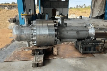
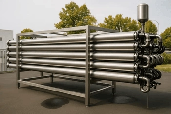
A U tube bundle heat exchanger is a shell-and-tube heat exchanger in which every tube in the bundle is bent into a U-shape — entering and exiting through the same single tube sheet at one end of the shell, with the U-bend free-floating at the opposite end. This design eliminates the second tube sheet entirely and leaves the tube bundle free to expand and contract thermally without any mechanical constraint from the shell.
That one structural fact — unconstrained thermal expansion — is what makes the U-tube bundle the preferred design for the most demanding thermal duties in heavy industry: high-pressure steam heaters, reactor feed and effluent exchangers, reboilers on distillation columns, and high-temperature services where the temperature differential between the tube-side and shell-side fluids would generate destructive thermal stresses in a fixed tube sheet design.
As a leading U tube bundle heat exchanger manufacturer in India, United Heat Exchangers designs and fabricates U-tube bundles to TEMA-R, TEMA-B, and TEMA-C standards for refineries, petrochemical plants, power stations, chemical processing, and offshore applications — ASME U-Stamp certified, HTRI-rated, and backed by a written thermal performance guarantee.
How a U-Tube Bundle Heat Exchanger Works
Animated walkthrough: U-bend flow path, thermal expansion absorption, and baffle crossflow — 3 minutes
Anatomy — Every Component and What It Does
Understanding why U-tube bundles outperform other designs for specific duties starts with understanding what each component does — and why the U-bend changes the engineering calculus entirely compared to a straight-tube design.
U-Tube Bundle Heat Exchanger — Cutaway Overview

Illustrative cutaway — single tube sheet, U-bends, segmental baffles, and two-pass tube-side flow
Shell
Cylindrical pressure vessel body containing the shell-side fluid. Material matched to shell-side corrosivity, operating temperature, and design pressure — from carbon steel to stainless or alloy for severe services.
Single Tube Sheet
The defining feature of a U-tube design. A single heavy plate welded to the shell at one end only — leaving the bundle free to grow thermally along its full length, eliminating the differential stress that fractures fixed tube sheet units.
U-Tube Bundle
Tubes bent into U-shapes with minimum bend radius that preserves wall thickness and avoids work-hardening cracks. The U-bend end floats freely inside the shell, absorbing all thermal expansion without mechanical constraint.
Channel and Channel Cover
End closure bolted to the tube sheet. An internal partition divides it into inlet and return compartments, directing tube-side fluid through the U-tubes. Removable cover gives access to tube ends for inspection.
Segmental Baffles
Disc-shaped plates with a cut segment positioned at calculated intervals to direct shell-side fluid in a crossflow pattern across the tube bundle. Baffle spacing and cut are HTRI-optimised to balance heat transfer against shell-side pressure drop.
Tie Rods and Spacers
Steel rods with spacer tubes cut to exact baffle pitch. They hold the baffle stack at precise spacing, preventing baffle migration under shell-side flow forces throughout the unit's operating life.
Shell-Side Nozzles
Flanged inlet and outlet connections on the shell body. Nozzle size, orientation, and inlet impingement protection are specified based on shell-side fluid velocity and phase to prevent tube erosion.
Support Saddles
Fabricated supports distributing the weight of shell, bundle, and fluid onto the supporting structure. On long shells, one saddle is fixed and the other slides — allowing the shell to expand axially under thermal load.
How a U Tube Bundle Heat Exchanger Works
The operating principle is straightforward — the engineering sophistication is in the baffle geometry, tube-side pass arrangement, and material selection that make the design perform at the specified duty across the full range of operating conditions.
Tube-Side Fluid Enters
Enters the channel inlet nozzle, fills the first-pass compartment, and flows into the inlet legs of all U-tubes simultaneously.
Travels the Full Length
Tube-side fluid travels toward the U-bend end, gaining or losing heat through the tube wall as it goes.
Reverses at the U-Bend
At the U-bend, the fluid reverses direction 180° and returns through the outlet leg — a natural two-pass arrangement in every U-tube design.
Shell-Side Fluid Crosses
Shell-side fluid is directed by segmental baffles in a crossflow pattern across the outside of the tube bundle, maximising the shell-side heat transfer coefficient.
Heat Transfers Through Tube Walls
Thermal energy migrates from the hotter fluid to the cooler fluid through the tube wall, governed by conductivity, wall thickness, film coefficients, and temperature differential.
Bundle Expands Freely
As temperatures change, the U-bend absorbs all thermal expansion. No bellows, no expansion joints, no differential thermal stress — the mechanical simplicity that defines U-tube durability in high-temperature service.
💡 Why two passes always? Every U-tube heat exchanger is inherently a two-pass design on the tube side — the inlet pass goes out, the return pass comes back through the same tube sheet. This doubles the effective tube length per unit of shell length and allows the design to approach true counter-current flow more closely — which is why U-tube units achieve tighter temperature approaches on the same heat transfer area.
Advantages and Limitations — The Honest Assessment
A U-tube bundle is the right answer for many applications — and the wrong answer for some. Understanding both sides is what allows the correct selection at the design stage, before a fabrication order is placed.
✔ Advantages
Where U-tube design genuinely outperforms alternatives
- Unrestricted thermal expansion — the U-bend accommodates any temperature differential without mechanical stress. No bellows required, even at differentials exceeding 200°C.
- Highest pressure capability — single tube sheet and no floating head internals make U-tube bundles the preferred configuration for HP steam, high-pressure hydrogen, and supercritical process fluids.
- Lowest cost for high-temperature, high-pressure service — eliminating the second tube sheet and floating head assembly reduces fabricated cost significantly for alloy constructions.
- Complete bundle removal — the entire tube bundle pulls out of the shell as a single unit for full access to shell interior and tube exterior surfaces.
- Longest service life in clean services — U-tube bundles in clean, non-fouling services routinely deliver 25–40 year service lives.
- Suitable for phase-change duties — steam heaters, reboilers, and condensers benefit from the U-tube design's ability to handle large temperature swings without structural compromise.
⚠ Limitations
Where a different design may be the better choice
- Inner U-bend tubes cannot be individually replaced — when a tube fails in the innermost rows, the standard repair is to plug it. Tight inner bend radii make extraction impractical without disturbing the entire bundle.
- Tube-side mechanical cleaning is not possible — straight brushes and rodding tools cannot navigate the U-bend. This makes U-tube bundles unsuitable for tube-side fouling services requiring mechanical descaling.
- Minimum tube-side flow velocity constraint — the two-pass arrangement splits tube-side flow across half the total tube count per pass. At low flow rates, tube count and diameter selection requires careful attention to velocity.
- U-bend area not cleanable on shell side — tight tube clustering at the U-bend end is difficult to access with mechanical cleaning tools. For shell-side fouling services, rod-baffle or NTIW designs may be preferable.
💡 The selection principle: If the tube-side fluid is clean, high-pressure, high-temperature, or a steam or condensate stream — and the shell-side handles the fouling burden — a U-tube bundle is almost always the correct choice. If the tube-side fluid is fouling and requires mechanical cleaning, a floating head or double-pipe design is the better answer. United Heat Exchangers makes this recommendation as part of every engineering proposal, not after fabrication.
U-Tube Bundle Configurations We Manufacture
Standard U-Tube Bundle (TEMA BEM / AEM / AEU)
The most widely used configuration — single tube sheet, fixed shell cover, removable channel cover. Suitable for the large majority of refinery, petrochemical, and chemical plant duties where tube-side fouling is not a primary concern. Manufactured in carbon steel, stainless steel, and alloy to TEMA-R, B, or C as specified.
U-Tube Kettle Reboiler (TEMA AKU / BKU)
A U-tube bundle in an oversized kettle shell with a weir at the tube bundle outlet end. Steam or hot process fluid heats the tube side; shell-side liquid boils and generated vapour exits through the vapour nozzle. The preferred U-tube configuration for distillation column reboiling duties.
U-Tube Steam Heater
Steam on the shell side, process fluid on the tube side — or the reverse, depending on fouling and pressure considerations. The U-tube's ability to absorb steam condensate temperature swings without thermal stress makes it the standard design for steam-heated process exchangers in refineries and chemical plants.
High-Pressure U-Tube Bundle
Designed for tube-side pressures above 3,000 psi — hydrogen recycle exchangers, HP steam generators, and supercritical process heaters. The single-tube-sheet construction eliminates the differential pressure sealing challenge of floating head designs. Heavy-wall tube sheet, small-diameter high-wall-thickness tubes, and full radiographic examination.
Alloy U-Tube Bundle (Titanium / Duplex / Hastelloy)
U-tube bundles in titanium, duplex 2205, super duplex 2507, Hastelloy C-276, or Inconel 625 for corrosive process fluids. The cost advantage over floating head construction is pronounced in expensive alloy materials — only one tube sheet needs to be machined from alloy plate.
Replacement U-Tube Bundle
A replacement bundle manufactured to match the shell, tube sheet bore pattern, nozzle layout, and flange dimensions of the existing vessel. We can also upgrade tube material, wall thickness, or baffle configuration if the original design is being re-rated for a new service.
Design Specifications and Standards
Every U tube bundle heat exchanger we manufacture is custom-engineered to your specific process data, site conditions, and project specification — using HTRI Xchanger Suite for thermal design and TEMA as the governing mechanical standard, with ASME BPVC Section VIII for pressure-containing components.
| Specification | Range / Options |
|---|---|
| Shell Inside Diameter | 150 NB (6 inch) to 2,500 mm (100 inch) and above for special applications |
| Shell Length | 1.0 m to 12.0 m (standard); longer shells available as multi-shell trains |
| Design Pressure — Tube Side | Full vacuum to 700 bar (10,000+ psi); high-pressure hydrogen service available |
| Design Pressure — Shell Side | Full vacuum to 150 bar (2,200 psi) standard; higher on enquiry |
| Design Temperature | -196°C (cryogenic / LNG service) to +650°C (high-temperature alloy service) |
| Tube Outside Diameter | 15.88 mm (5/8 inch) to 38.1 mm (1½ inch) standard; custom diameters on request |
| Tube Wall Thickness | BWG 10 to BWG 22 (1.65 mm to 3.40 mm); heavier walls for high-pressure and corrosion allowance |
| Minimum U-Bend Radius | 1.5 × tube OD (minimum per TEMA); larger bend radii specified for work-hardened materials |
| Tube Material | Carbon steel (A179 / A192), 304/316L/321/904L stainless, duplex 2205, super duplex 2507, titanium Gr.2, admiralty brass, CuNi 90/10, Hastelloy C-276, Inconel 625 |
| Tube Sheet Material | Carbon steel, 316L clad, titanium clad, duplex; single tube sheet machined from solid forging or plate |
| Shell Material | Carbon steel, 304/316L stainless steel, duplex 2205, alloy steel — matched to shell-side fluid |
| Baffle Type | Segmental, double segmental, triple segmental, rod baffle, and NTIW for low-pressure drop applications |
| Tube-to-Tube Sheet Joint | Expanded, strength-welded, or expanded-and-welded per TEMA; full penetration weld for lethal and high-pressure services |
| Design Code | TEMA-R / B / C; ASME BPVC Section VIII Div. 1 & 2; ASME Section IX welding; PED (Europe); IBR (India steam service) |
| NDE Requirements | Radiography (spot or 100%), ultrasonic testing, PMI, hydrostatic test at 1.5× design pressure — per applicable code and inspection class |
Material Selection Guide
Material selection for a U-tube bundle is a set of independent decisions — tubes, tube sheet, shell, channel, and baffles — each driven by fluid chemistry, operating temperature, pressure, and minimum acceptable service life. Getting this right at the design stage is what separates heat exchangers that run 30 years from ones that require emergency replacement in 5.
Carbon Steel (SA-179 / SA-192)
Standard tube material for non-corrosive process fluids, cooling water, steam, and condensate. Most cost-effective for large surface area requirements. Corrosion allowance of 1.5–3.0 mm specified depending on service life requirement.
304 / 316L Stainless Steel
For mildly corrosive process fluids, pharmaceutical streams, food-grade applications, and services where carbon steel corrosion would contaminate the process fluid. 316L provides improved chloride pitting resistance over 304.
321 / 347 Stainless Steel
Stabilised austenitic grades — titanium-stabilised (321) or niobium-stabilised (347) — for high-temperature services where sensitisation of standard 304/316 would cause intergranular corrosion.
Duplex 2205 Stainless Steel
Approximately twice the yield strength of 316L — allowing thinner tube walls for the same pressure rating — with excellent resistance to chloride stress corrosion cracking (SCC) that fails austenitic grades in warm chloride environments.
Super Duplex 2507
Higher chromium, molybdenum, and nitrogen content than 2205 gives outstanding resistance to pitting and crevice corrosion in high-chloride and high-temperature seawater. PREN above 40 — the accepted threshold for reliable seawater service.
Titanium Grade 2
Essentially immune to seawater corrosion, chloride pitting, and biofouling at typical marine operating temperatures. Higher material cost is offset by elimination of corrosion-related replacement cycles over the asset life.
Hastelloy C-276
Outstanding resistance to concentrated acids, wet chlorine, chloride solutions, and both oxidising and reducing environments. Specified for chemical processing where stainless and duplex grades are inadequate.
Admiralty Brass / CuNi 90/10 and 70/30
Copper-based alloys with established track records in cooling water and seawater service. CuNi 90/10 and 70/30 provide natural biofouling resistance — long the standard in marine heat exchangers before titanium and duplex became cost-competitive.
Industries and Applications
| Industry | Typical U-Tube Bundle Application | Why U-Tube Is Specified |
|---|---|---|
| Oil & Gas Refining | Crude preheat train exchangers, reactor feed/effluent exchangers, stripper reboilers, naphtha splitter reboilers, hydrogen recycle gas coolers | High temperature differentials in feed/effluent service; high tube-side pressure in hydrogen service — both demand unconstrained thermal expansion |
| Petrochemicals | Ethylene plant feed/effluent exchangers, styrene reactor feed preheaters, propylene fractionator reboilers, aromatics extraction reboilers | Large temperature swings in reactor feed service; high fouling tendency on shell side makes complete bundle removal essential |
| Power Generation | Feed water heaters (FWH), condensate heaters, LP and HP closed feed water heaters, extraction steam heaters | Steam on shell side with large temperature differentials; U-tube design standard in power plant feed water heater trains worldwide |
| Chemical Processing | Reactor preheaters, distillation column reboilers, solvent heaters, thermal fluid heaters, process steam heaters | Clean tube-side services — steam, thermal oil, process condensate — benefit from U-tube's high-pressure and high-temperature capability |
| LNG & Gas Processing | Amine lean/rich exchangers in gas sweetening units, glycol heat exchangers, refrigerant economisers, gas/gas heat exchangers | High temperature differentials between lean and rich amine streams; fouling tendency on rich amine side managed by shell-side placement and complete bundle pullout |
| Fertilizer & Ammonia | Ammonia synthesis feed/effluent exchangers, converter feed preheaters, high-pressure steam generators, shift converter feed heaters | Very high pressures (150–300 bar) and large temperature differentials in ammonia synthesis loops — U-tube is the only practical single-shell design |
| Offshore & Marine | Produced water coolers, gas/gas exchangers on platforms, wellhead gas coolers, closed cooling water heaters | Limited footprint; alloy tube materials (titanium, super duplex) for corrosive service; complete bundle removal during offshore maintenance windows |
| Pharma & Fine Chemicals | Process fluid heaters and coolers, solvent recovery condensers, WFI system heat exchangers, sterile process service | 316L or Hastelloy tube materials; electropolished finish available; CIP-compatible designs; full traceability documentation for regulated service |
Ready to Size Your U-Tube Bundle?
Send us your process datasheet and our engineering team will return a sized configuration with budgetary pricing within 48 hours.
U-Tube vs Fixed Tube Sheet vs Floating Head — Which Is Right?
The three most common shell-and-tube configurations each solve a different engineering problem. The right choice at the design stage avoids expensive redesign or premature replacement later.
| Criterion | U-Tube Bundle | Fixed Tube Sheet | Floating Head |
|---|---|---|---|
| Thermal Expansion Handling | Excellent — U-bend absorbs all differential expansion freely | ⚠ Limited — requires expansion bellows for large temperature differentials | Good — floating head moves with tube bundle expansion |
| Maximum Design Pressure | Highest — single tube sheet, no floating head seal | High — two fixed tube sheets, no moving parts | ⚠ Moderate — floating head seal limits maximum pressure |
| Tube-Side Mechanical Cleaning | Not possible — U-bend prevents straight rodding tools | Yes — straight tubes accessible from both ends | Yes — straight tubes accessible from both ends |
| Shell-Side Bundle Removal | Yes — complete bundle pulls out of shell | No — tube sheet welded to shell at both ends | Yes — complete bundle pulls out of shell |
| Fabricated Cost | Lowest for alloy and high-pressure construction | Lowest for carbon steel standard service | ⚠ Highest — floating head internals add machining and assembly cost |
| Inner Tube Replaceability | ⚠ Inner rows plugged rather than replaced | All tubes individually replaceable | All tubes individually replaceable |
| Best Application | High-pressure, high-temperature, clean tube-side — steam heaters, reboilers, feed/effluent, HP hydrogen | Moderate temperature differential, clean tube side — general process cooling and heating | Fouling tube-side fluid requiring mechanical cleaning — crude oil, heavy process streams |
💡 Our recommendation approach: When you submit your process data, our engineers evaluate all three configurations against your duty, fouling assessment, operating pressure, temperature differential, maintenance access, and budget — and recommend the configuration that delivers the best total lifecycle value. The recommendation comes before the quotation, not after.
Why United Heat Exchangers
Manufacturing a U-tube bundle is not a commodity fabrication job. Getting the U-bend radius right, qualifying the tube-to-tube-sheet weld procedure for the chosen materials, confirming the HTRI thermal rating accounts for the true baffle geometry including the U-bend end zone, and issuing documentation that a plant's inspection authority will accept without query — all of this requires focused expertise, not general fabrication capability. United Heat Exchangers has delivered this expertise consistently for over 35 years.
Established in 1989 in Coimbatore with an unbroken record of heat exchanger manufacturing. U-tube bundles are a core product, not an occasional special job. Our tooling, bending equipment, and qualified welding procedures are developed specifically for U-tube construction.
Every U-tube bundle is thermally rated using HTRI Xchanger Suite — including correct modelling of the U-bend zone, baffle geometry, tube-side pass arrangement, and fouling resistances. We issue a written thermal performance guarantee tied to your process conditions.
All pressure components are manufactured and inspected to ASME BPVC Section VIII Division 1. All pressure welds are performed to ASME Section IX qualified procedures. Both certifications are independently audited — required for US, Canadian, Middle East, and most international process plant projects.
U-tube bending is a qualified process — particularly for work-hardening materials like austenitic stainless and duplex grades. Our bend procedures are qualified per ASME and TEMA, with hardness testing and dimensional verification at the U-bend for every critical material combination.
Mill test reports with heat number traceability, radiography records, hydrostatic test certificate, TEMA data sheet, tube sheet drilling layout, tube-to-tube-sheet weld procedure qualification, and Manufacturer's Data Report — issued as standard with every ASME-stamped unit.
When a U-tube bundle reaches end of life in an existing shell, we manufacture the replacement to the original tube sheet bore pattern, tube pitch, and nozzle layout — with the option to upgrade tube material, wall thickness, or baffle configuration if the unit is being re-rated for new service.
Delivery and What's Included
What's Included with Every U Tube Bundle Heat Exchanger Order
- Written HTRI thermal performance guarantee — rated for your process conditions, including U-bend zone correction and fouling resistances, issued before and confirmed at delivery
- ASME U-Stamp Manufacturer's Data Report (MDR) — signed and stamped by the Authorised Inspector, covering all pressure-containing components
- Material certifications (MTRs) — mill test reports for all tubes, tube sheet, shell, channel, and nozzle materials, traceable to heat and lot number
- Weld procedure qualification records (WPS / PQR) — for all pressure welds including tube-to-tube-sheet joints and shell seam welds, per ASME Section IX
- NDE records — radiography film and reports, UT records, or PMI certificates as applicable to the design code and inspection class
- Hydrostatic test certificate — tube side and shell side each tested to 1.5× design pressure; third-party witness available at no additional lead time
- TEMA data sheet — fully completed to TEMA standard format; tube sheet drilling layout drawing; nozzle orientation drawing
- U-bend qualification records — bend procedure qualification, hardness test results at bend, and dimensional verification for alloy tube materials
- Operation and maintenance manual — shell-side cleaning procedures, chemical cleaning guidance for tube side, inspection interval recommendations, torque values, and spare parts list
- Lifetime technical support — engineering assistance for thermal re-rating, replacement bundle enquiries, and performance troubleshooting throughout the operating life of every unit
Get a Free U Tube Bundle Heat Exchanger Quote in 48 Hours
Share your process fluid, flow rates, inlet and outlet temperatures, design pressure, temperature differential, site conditions, and applicable codes — and our engineering team will return a technical proposal with budgetary pricing within 48 hours.
Frequently Asked Questions
What is a U tube bundle heat exchanger?
This single-tube-sheet construction makes it the preferred design for high-pressure, high-temperature, and large temperature-differential services where a fixed tube sheet design would require expansion bellows or accumulate destructive thermal stresses over time.
What is the main advantage of a U-tube design over a fixed tube sheet?
A fixed tube sheet design ties the tube bundle mechanically to the shell at both ends. If the temperature differential is large, this creates axial stress that must be managed with an expansion bellows. The U-tube design eliminates this entirely at lower cost and without a potential leak point.
Can U-tube heat exchangers be mechanically cleaned on the tube side?
This is why U-tube designs are specified for steam, condensate, hydrogen, and clean process fluids — not for fouling tube-side services that require mechanical descaling. If tube-side fouling is a concern, a floating head or double-pipe design is the correct choice.
What happens when a tube fails in a U-tube bundle?
Tube replacement in outer rows is sometimes practical, but inner-row tubes with tight U-bend radii are effectively irreplaceable without disturbing the entire bundle. Plugging isolates the tube from both fluid circuits. Beyond the TEMA-defined plugging limit, a new bundle is the appropriate response.
What TEMA class is appropriate for refinery U-tube heat exchangers?
United Heat Exchangers designs all refinery U-tube bundles to TEMA-R as the default, not as an upsell. The more stringent requirements reflect the severity and consequence of failure in refinery operating environments.
What is the minimum U-bend radius and why does it matter?
For work-hardening materials such as austenitic stainless steel and duplex grades, larger bend radii and post-bend annealing are specified to restore material properties. United Heat Exchangers qualifies all U-tube bending procedures per ASME and verifies wall thickness and hardness at the bend for every critical material combination.
What is the delivery time for a U-tube bundle heat exchanger from United Heat Exchangers?
All lead times run from order confirmation and approved drawings. Contact us with your shutdown window and we will confirm achievability before you commit to the order.
Author: Senthil Kumar, Technical Director — United Heat Exchangers Pvt. Ltd. | Last Updated: May 2026