Author: Senthil Kumar, Technical Director | Updated: May 2026
Table of Contents
- What Is a Filter Vessel?
- How Filter Vessels Work
- Types of Filter Vessels
- Internal Components Explained
- Design Specifications and Standards
- Vessel Material Selection
- Industries and Applications
- How to Size a Filter Vessel
- Maintenance and Filter Replacement
- Why Choose United Heat Exchangers
- Delivery and Support
- Frequently Asked Questions
- Request a Free Quote

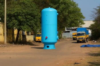
What Is a Filter Vessel and Why Is It Critical?
A filter vessel is a pressure-rated container holding filter media — cartridges, bags, or strainers — that removes contaminants from liquids and gases in industrial processes. Contaminated fluid enters, passes through filter media, and exits clean and ready for downstream equipment.
Filter vessels protect equipment from damage caused by unfiltered fluids. Suspended solids destroy downstream compressors, pumps, and heat exchangers far more expensively than a filter vessel costs. A properly sized vessel extends equipment life and significantly reduces maintenance expenses.
As a leading filter vessel manufacturer in India, United Heat Exchangers manufactures ASME U-Stamp certified pressure filter vessels for oil and gas, petrochemicals, power generation, and water treatment — custom-engineered for your contamination rate and operating pressure.
How Filter Vessels Work — Process and Flow
The operating principle is straightforward: contaminated fluid enters one port, flows through filter media inside the vessel, and clean fluid exits another port. The filter media traps particulate, water droplets, or contaminants while allowing the process fluid to pass.
Contaminated Fluid Enters
Unfiltered process fluid enters the vessel inlet port carrying suspended contaminants — sand, rust, water droplets, polymers, or process solids.
Flows Into Top Chamber
Inlet nozzle directs fluid into the upper chamber above the filter element. Fluid distributes evenly across the filter media — avoiding localized bypass or jet impingement.
Passes Through Filter Media
Fluid permeates through the filter — cartridge, bag, or strainer — leaving contaminants on the media surface. Media micron rating determines what size particles are captured.
Accumulates in Clean Chamber
Filtered fluid collects in the lower chamber — the clean side of the vessel. Pressure on the clean side is lower because the filter media creates a small pressure drop across it.
Exits Through Outlet Nozzle
Clean fluid flows out of the vessel outlet port toward the next process step. Pressure drop through the filter is minimal if correctly sized — typically 0.1–0.3 bar at design flow.
Contaminants Held in Media
Captured contaminants remain on the filter media until the media is changed. A differential pressure switch alerts the operator when the media is clogged and needs replacement.
💡 Pressure drop increases over time: As the filter media accumulates contaminants, the pressure drop across the filter rises. Operators monitor this with a differential pressure gauge or switch. When pressure drop reaches the alarm setpoint — typically 0.5–1.0 bar — the media is changed. Running the filter beyond this point risks filter media bypass or damage to downstream equipment.
Types of Filter Vessels — Selection by Application
Filter vessel types are classified by the filter media used and the internal arrangement. Each type serves specific contamination removal needs and operating pressure ranges.
Cartridge Filter Vessel
Most popular — dependable performance, strong dirt-holding capacityCylindrical pleated cartridge elements housed inside a vertical or horizontal pressure vessel. Cartridges are disposable — the entire element is replaced when clogged. The most cost-effective filtration for general process service.
- Standard choice for oil, water, fuel, and hydraulic fluid filtration
- Cartridges available in 1, 5, 10, 25, 50 micron ratings
- Single or multi-cartridge arrangements in one vessel
- Dirt-holding capacity 50–200+ grams per cartridge depending on media depth
- Operating pressure range 1–40 bar standard; higher on request
Bag Filter Vessel
Large dirt capacity — industrial bulk fluid filtrationLarge woven or non-woven fabric bags suspended inside the vessel. Fluid enters the bag interior and exits through the outer wall into the clean chamber. Bags are removed and replaced when full. Used for high-contamination-rate fluids where frequent cartridge changes are impractical.
- Dirt-holding capacity 500+ grams — 10–20× higher than cartridge filters
- Rated for coarse filtration — typically 25–250 micron range
- Most economical for bulk liquid filtration — crude oil pre-filtration, slurry handling
- Bag removal and disposal is manual labor-intensive compared to cartridge change
- Operating pressures up to 20–35 bar depending on bag material
Strainer Vessel
Mesh screen filtration — simple, robust, long lifeStainless or carbon steel mesh screen element suspended inside the vessel. Fluid passes through the mesh openings while solids and agglomerates are trapped on the upstream side. Stainless mesh can be cleaned with brushing or backflush without removal.
- Coarse filtration — 100–500 micron typical; not suitable for fine particle removal
- Mesh element is reusable — clean and reinstall without replacement cost
- Very high dirt-holding capacity — suitable for heavily contaminated fluids
- Low pressure drop relative to dirt capacity — suitable for high-flow applications
- Operating pressures up to 100 bar — highest rating of all filter types
Multimedia Filter Vessel
Multi-layer beds — water treatment and polishingVertical vessel with multiple layers of filter media — sand, anthracite, garnet — stacked to progressively refine particle removal from coarse to fine. Fluid enters at the top, percolates downward through the beds, and exits at the bottom. Used primarily in water treatment and condensate polishing.
- Removes color, turbidity, and fine suspended solids from water streams
- Operates at low pressures — gravity or small pumps; not suitable for high-pressure service
- Backwash cleaning — flow reversed periodically to clean the beds without removing them
- Very high dirt capacity — typically days between backwash intervals
- Standard in water purification, power plant condensate polishing, and cooling tower water treatment
Air/Gas Filter Vessel
Compressed air and inert gas purificationCartridge or coalescer element designed to remove water droplets, oil mist, and particulates from compressed air or nitrogen streams. Coalescer elements capture liquid droplets and drain them continuously from the vessel. Suited to compressed air systems where moisture control is critical.
- Removes water, oil, and particulates down to 0.3 micron
- Integral drain or separator — collects liquid contaminants for removal
- Operating pressure range 1–30 bar depending on element type
- Essential for pneumatic instruments, paint spray systems, and food production air
- Lower dirt capacity than liquid filters — frequent element change required in humid environments
Internal Components Explained

Vessel Body — Upper Chamber
The contaminated fluid chamber above the filter element. Sized to direct inlet flow evenly across the full filter media surface — preventing localized bypass. Upper chamber design is critical — poor distribution lets contaminants bypass the filter and reach downstream equipment.
Filter Media Element
The actual filtration component. Types: pleated cartridge, woven or non-woven bag, mesh screen, or multimedia bed. Media material selected per the fluid type — polyester for oils, polypropylene for water, stainless steel mesh for abrasive slurries. Micron rating defines particle removal efficiency.
Element Support Cage
Internal cage structure supporting the filter element and preventing collapse under pressure. The cage allows fluid to flow from outside the cartridge to inside, preventing bypass flow through the cage openings. Cage material: plastic for cartridges, welded steel for bag filters.
Vessel Body — Lower Chamber
The clean fluid collection chamber below the filter element. Sized to minimize turbulence and allow entrained air to release. The outlet nozzle draws from the lower chamber — ensuring filtered fluid with minimal air carryover is delivered to downstream equipment.
Inlet and Outlet Nozzles
Flanged or threaded connections rated to the vessel design pressure. Inlet nozzle has a diffuser — a perforated tube or baffle directing inlet flow away from the filter element to ensure distribution. Outlet nozzle is positioned low in the clean chamber to allow settling of any remaining solids.
Drain and Vent Connections
Low-point drain cock allows accumulated contaminants and condensate to be manually drained from the vessel. High-point vent or air release valve prevents air locking during startup. Both are essential safety features — drain prevents backpressure on the filter media, vent prevents vacuum formation during shutdown.
Pressure and Differential Pressure Gauges
Inlet pressure gauge shows the upstream system pressure. Differential pressure gauge or switch across the filter element alerts the operator when the filter is clogged. When differential pressure reaches the alarm setpoint — typically 0.5–1.0 bar — the element requires replacement to prevent bypass.
Vessel Head and Access Cover
The removable or hinged cover at the top — secured by bolts or a side-swing clamp for rapid opening. Access cover must be removable for element replacement without emptying the entire vessel. Quality access design significantly reduces maintenance labor and downtime.
Filter Vessel Design Specifications and Standards
Every filter vessel is engineered to your exact process requirements — fluid type, contamination rate, flow rate, and operating pressure.
| Specification | Range / Options |
|---|---|
| Type | Cartridge, bag, strainer, multimedia, air/gas, coalescer |
| Design Pressure | 1 bar to 100 bar; vacuum vessels on request |
| Design Temperature | -20°C to +150°C standard; cryogenic and high-temp on enquiry |
| Flow Rate Capacity | 1 m³/h (small cartridge) to 500+ m³/h (large multimedia or strainer) |
| Number of Elements | Single element to 100+ parallel elements in one vessel frame |
| Filter Media Micron Rating | 1 to 500 micron depending on element type and application |
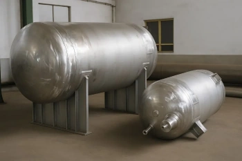
| Vessel Orientation | Vertical (most common), horizontal (space-constrained installations) |
| Vessel Material | Carbon steel, stainless steel 304/316L, duplex 2205, higher alloys on request |
| Element Change Method | Top access cartridge pull, side swing bag access, top backwash for multimedia |
| Design Code | ASME BPVC Section VIII Div. 1 & 2, PED (Europe), Chinese GB code |
| Pressure Rating Method | Full vacuum to 100+ bar; custom ratings per ASME analysis |
| Fouling vs Pressure Drop | Optimized per contamination rate — larger surface area = longer element life, lower pressure drop |
Vessel Material Selection — Matching to Fluid and Environment
Filter vessel material selection depends on the process fluid chemistry, operating temperature, ambient atmosphere, and required service life. Wrong material choice leads to corrosion perforation and unplanned shutdown between maintenance intervals.
Carbon Steel (Standard)
Standard vessel material for clean mineral oils, water, fuels, and process liquids at moderate temperatures. Internal and external surfaces typically coated — epoxy inside, paint outside. Cost-effective and proven in millions of filtration applications worldwide.
304 Stainless Steel
Specified for water, aqueous solutions, condensate, and mild chemical service. Provides corrosion resistance for moderately corrosive process fluids. Standard choice for food processing, pharmaceutical, and power plant condensate filtration where carbon steel would corrode unacceptably.
316L Stainless Steel
Enhanced chloride and acid resistance over 304. Specified for seawater filtration, chloride-containing process streams, and chemical plant service. Higher cost justified by extended service life and zero maintenance related to corrosion in aggressive fluid service.
Duplex 2205 Stainless
Exceptional strength and chloride resistance — specified for produced water treatment, seawater desalination pre-filters, and high-pressure high-salinity oil field service. Twice the yield strength of 316L allows thinner walls at the same pressure rating.
Epoxy Lined Carbon Steel
Carbon steel vessel with industrial epoxy coating applied to interior surfaces — protecting from corrosive fluids without the cost of solid stainless construction. Epoxy thickness and cure are critical to prevent coating failure and corrosion breakthrough.
Hastelloy C-276 (Specialty)
Specified for extremely corrosive chemical process streams — strong acids, mixed oxidizing and reducing environments, and process streams that defeat standard stainless steels. Extreme cost reserved for high-value chemical and refinery service where material failure is non-negotiable.
Industries and Applications — Where Filter Vessels Are Essential
| Industry | Filtration Application | Filter Type Specified |
|---|---|---|
| Oil & Gas Refining | Crude oil pre-filtration, fuel oil filtration, produced water treatment, process fluid filtration | High-pressure cartridge filters for crude; bag filters for pre-filtration; strainers for high-contamination service |
| Petrochemical Processing | Process stream filtration, solvent recovery, cooling tower water treatment, acid/chemical filtration | Cartridge filters for process streams; 316L stainless or Hastelloy for corrosive fluids; bag filters for bulk handling |
| Power Generation | Condensate polishing, cooling water filtration, lube oil filtration, compressed air purification | Multimedia filters for condensate; cartridge filters for lube oil; coalescer filters for instrument air |
| Water Treatment & Municipal | Drinking water purification, wastewater pre-treatment, cooling water polishing, recycled water treatment | Multimedia filter vessels standard; strainer filters for coarse intake screening; high-flow configurations |
| Food & Beverage Production | Beverage filtration, cooking oil filtration, milk processing, juice clarification, water treatment | 304 or 316L stainless cartridge filters; food-grade materials and sealing only; regular certification traceability |
| Pharmaceutical & Biotech | Process water filtration, sterile filtration, solvent purification, compressed air supply | 316L stainless steel or higher alloy; electropolished surfaces where required; full traceability and sterilization capability |
| Chemical Processing | Aggressive chemical stream filtration, catalyst separation, solvent recovery, acid/caustic filtration | 316L for mildly corrosive; Hastelloy C-276 for extreme environments; acid-resistant gasket materials |
| Marine & Offshore | Seawater intake filtration, fuel oil treatment, hydraulic fluid filtration, produced water treatment | 316L or duplex stainless for seawater exposure; high-pressure cartridge filters for marine fuel systems |
Filter Vessels for Every Industrial Filtration Duty
From oil and gas pre-filters to power plant condensate polishing — ASME U-Stamp certified, custom-engineered for your contamination rate and flow. Free quote in 48 hours.
Request My Free Quote →How to Size a Filter Vessel Correctly
Under sizing a filter vessel leads to rapid element clogging, frequent changes, and high operating cost. Oversizing wastes capital. Correct sizing balances capital cost, dirt-holding capacity, and acceptable pressure drop.
Define Flow Rate and Contamination
Know the process fluid flow rate (m³/h), contamination level (particles per liter or grams per liter), and acceptable change interval (hours or weeks). Higher contamination rate demands larger filter surface area to hold more dirt before clogging.
Select Filter Media Type
Choose between cartridge, bag, strainer, or multimedia based on the fluid type and contamination characteristics. Cartridge filters are default for general service; bags for high dirt capacity; strainers for very coarse or abrasive slurries.
Calculate Minimum Surface Area
Divide the flow rate by the acceptable face velocity for the media type. Face velocity determines pressure drop — lower velocity means lower pressure drop and longer element life, but larger vessel. Typical face velocity: 2–4 m/min for cartridge, 1–2 m/min for bag.
Estimate Element Change Interval
Multiply the dirt-holding capacity (grams) by the element change interval you want (typically 1,000–2,000 hours). The product is the tolerable contamination rate in grams per 1,000 hours. Size the filter large enough that this contamination rate loads the element gradually, not suddenly.
Verify Pressure Drop Budget
Calculate pressure drop across the clean filter at your design flow. Most systems budget 0.1–0.3 bar pressure drop through the filter. If calculated pressure drop exceeds your available budget, increase filter surface area or decrease flow velocity — both require larger elements or multiple elements in parallel.
Specify Design Pressure and Margin
Design the vessel for the maximum inlet pressure plus safety margin. If the process operates at 10 bar, design the vessel for 15 or 20 bar — this margin prevents vessel damage if a downstream blockage causes backpressure. Higher design pressure requires thicker vessel walls and higher cost.
💡 Rule of thumb for element life: A properly sized filter vessel with clean cartridge elements should run 1,000–2,000 operating hours before the element change alarm sounds. If your change interval is under 500 hours, the filter is undersized for your contamination rate. If over 3,000 hours, you have excess capacity that can be optimized for cost reduction.
Maintenance and Filter Element Replacement
Proper maintenance extends filter vessel life and maintains consistent downstream equipment protection.
| Task | Frequency | Action Required |
|---|---|---|
| Pressure Drop Monitoring | Continuous — log differential pressure daily or at shift change | Watch for trending increase in ΔP. When differential pressure reaches the alarm setpoint (typically 0.5–1.0 bar), schedule element replacement before the next operating shift |
| Element Replacement — Cartridge | When alarm activates — typically 1,000–2,000 hours depending on contamination rate | Close inlet isolation valve, vent vessel, open top access cover, withdraw cartridge cage, replace cartridge, reinstall cage, close cover, open vent, restore inlet flow |
| Element Replacement — Bag | When alarm activates or when visual inspection shows bag is visibly clogged | Close inlet valve, relieve pressure, open side access door, withdraw bag cage, remove full bag (discard), insert new bag, secure cage, close door, reopen inlet |
| Element Cleaning — Strainer | When differential pressure reaches alarm — typically 500–1,000 hours | Close inlet valve, relieve vessel pressure, open element cage, withdraw mesh screen, brush or backflush mesh with clean solvent or water, rinse thoroughly, reinstall, close cage, restore pressure and flow |
| Backwash — Multimedia | When pressure drop increases by 0.2–0.3 bar or every 24–48 hours during continuous operation | Close normal flow valve, open backwash valve, run backflush pump for 10–15 minutes, close backflush, reopen normal flow. Monitor backwash discharge for clarity — repeat if discharge is still murky |
| Drain Cock Inspection | Weekly during operation | Open low-point drain cock briefly to confirm it opens freely and the drain line is not blocked. Close. Any accumulation of water or sludge indicates the filter is capturing moisture or biological growth — increase element change frequency or add demulsified to the process |
| Vent and Safety Valve Check | Monthly | Confirm the high-point air vent opens freely during startup (listen for hissing air release at first flow). Confirm the low-point drain is not blocked and can be opened by hand without excessive force |
| Inlet and Outlet Nozzle Inspection | Quarterly or when pressure drop is abnormally high | Check flanges for corrosion, leaks and loose bolts. Check gaskets for swelling or degradation. Tighten bolts if loose. Replace gaskets if damaged or weeping. Any leakage indicates pressure testing and possible vessel or element damage |
| Vessel Corrosion Inspection | Annual for external; every 2–3 years for internal (internal inspection during turnarounds) | Check for rust spots, paint damage, or corrosion staining on external surfaces. Internal inspection checks for pitting or scale on shell and vessel head. Light rust can be brushed and touched up; heavy corrosion requires engineer evaluation for remaining wall thickness |
Why Choose United Heat Exchangers for Filter Vessels
A filter vessel that fails prematurely or leaks at the gasket costs far more in downtime and cleanup than the original equipment investment. United Heat Exchangers designs every vessel to remain leak-free and fully functional for 20+ years of operation.
35+ Years Filtration Equipment Expertise
Established in 1989. Filter vessels are a core product alongside heat exchangers. Every design, fabrication, and testing discipline is applied to produce equipment that operators trust.
ASME U-Stamp Certification
All pressure-rated filter vessels are manufactured to ASME BPVC Section VIII Division 1. U-Stamp MDR and material certifications issued with every unit. Independently audited — current and active certifications.
Right Material for Your Fluid
We assess your process fluid chemistry, temperature, and ambient exposure. Carbon steel for oils and standard water; 316L for chemical and seawater; Hastelloy for aggressive service. No generic default material applied.
Correctly Sized Every Time
Undersizing wastes money through frequent element changes; oversizing wastes capital. We calculate the right surface area for your contamination rate and change interval, balancing cost and performance.
Complete Documentation
MTRs, hydrostatic test certificates, access drawings, element replacement spare list, and operation manual issued as a complete package. No follow-up documentation requests.
Lifetime Spares and Support
Replacement elements, gaskets, and spare cartridges are manufactured to order throughout the service life of every vessel. Technical support for troubleshooting and element upsizing available on demand.
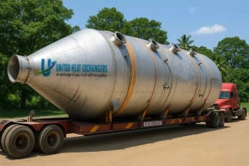
Delivery and What's Included
What's Included with Every Filter Vessel Order
- ASME U-Stamp Manufacturer's Data Report (MDR) — Authorized inspector's signature for pressure-rated vessels
- Material certifications (MTRs) — mill test reports for shell, heads, nozzles, and all pressure-containing components
- Hydrostatic test certificate — vessel pressure tested to 1.5× design pressure; third-party witness available
- Access and element replacement drawing — clear dimensions and procedure for safe element withdrawal and replacement
- Filter element specification and spare list — cartridge or bag part numbers for future replacement; recommended spare inventory
- Pressure drop and performance curves — outlet pressure drop as a function of flow rate at clean and at full-life element condition
- Installation and commissioning guide — piping connections, isolation valve requirements, vent and drain setup, startup checklist
- Operation and maintenance manual — element replacement step-by-step procedure, safety warnings, drain and vent operation, troubleshooting guide
- Lifetime technical support — element upsizing, replacement vessel sizing, troubleshooting abnormal pressure drop, and spare parts support
Get a Free Filter Vessel Quote in 48 Hours
Describe your process fluid type, flow rate, level of contamination, desired interval between element changes, design pressure, and any space restrictions. Our engineering team selects the right type, sizes the vessel, and delivers a technical proposal within 48 hours.
Request My Free Quote →Frequently Asked Questions About Filter Vessels
What is a filter vessel and what does it do?
A filter vessel is a pressure-rated container holding filter media that removes contaminants from process fluids. Contaminated fluid enters one port, passes through the filter media, and clean fluid exits another port. The vessel shields equipment downstream from contaminants in the process stream, such as water droplets and suspended solids.
What is the difference between a cartridge filter and a bag filter vessel?
Cartridge filters use pleated cylindrical elements with high dirt-holding capacity per unit cost — suitable for moderate to high contamination service. Bag filters use large woven bags with 5–10× higher dirt capacity but are more labor-intensive to change. Choose cartridge for general service; bag for high-contamination or unattended operation where frequent changes are impractical.
How often should filter elements be changed?
Change frequency depends on contamination rate, filter surface area, and desired change interval. A properly sized filter should run 1,000–2,000 hours before the differential pressure alarm sounds. If you're changing elements every 500 hours, the filter is undersized and you're losing money to frequent maintenance. If over 3,000 hours, you have excess capacity available for cost optimization.
What happens if a filter element is not changed when the differential pressure alarm sounds?
Running a clogged filter beyond the alarm setpoint risks filter media bypass — unfiltered contaminated fluid flows around the media and reaches downstream equipment, defeating the filtration purpose. Additionally, continued high pressure drop can damage the element structure, creating collapsed media that cannot be cleaned for reuse and may shed fibers into the process fluid.
Can I use a filter vessel for both oil and water?
Not recommended without cleaning and element change. If you switch from mineral oil to water without flushing the vessel, any residual oil will contaminate the new water service. Similarly, switching from water to oil requires a clean oil-compatible element. Always flush the vessel and change to a fresh element appropriate for the new service fluid.
What design pressure should I specify for my filter vessel?
Design pressure should equal the maximum inlet pressure plus a safety margin — typically 50% higher than operating pressure. If your process operates at 10 bar inlet, design the vessel for 15 or 20 bar. This margin provides protection against transient pressure spikes from pump startup, unexpected downstream blockage, or thermal expansion. Higher design pressure increases vessel wall thickness and cost, but prevents failure risk.
Can I clean and reuse cartridge filter elements instead of replacing them?
Generally not recommended. Cartridge elements are designed as disposable — their pleated paper or synthetic fiber media sheds fibers after a few cleaning cycles, releasing contaminants into the process instead of capturing them. Bag filters and strainer mesh can be cleaned and reused many times. Always follow the element manufacturer's guidance — some specialty cartridges allow limited cleaning, while standard elements do not.
What is the delivery time for a filter vessel from United Heat Exchangers?
Standard carbon steel or stainless steel cartridge and bag filter vessels deliver in 6–10 weeks from order confirmation and approved drawings. High-pressure vessels and multiple-element arrangements deliver in 10–16 weeks. For projects involving the shutdown of process units, expedited schedules are available.
Author: Senthil Kumar, Technical Director — United Heat Exchangers Pvt. Ltd. | Last Updated: May 2026