Floating Head Heat Exchanger
Request a QuoteTable of Contents
- What Is a Floating Head Heat Exchanger?
- Why Floating Head — The Engineering Case
- Anatomy — Every Component Explained
- How It Works
- TEMA S, T, and W — Three Configurations
- Design Specifications and Standards
- Material Selection Guide
- Industries and Applications
- Floating Head vs U-Tube vs Fixed Tube Sheet
- Why United Heat Exchangers
- Delivery and What's Included
- Frequently Asked Questions
- Request a Free Quote
What Is a Floating Head Heat Exchanger?
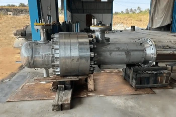
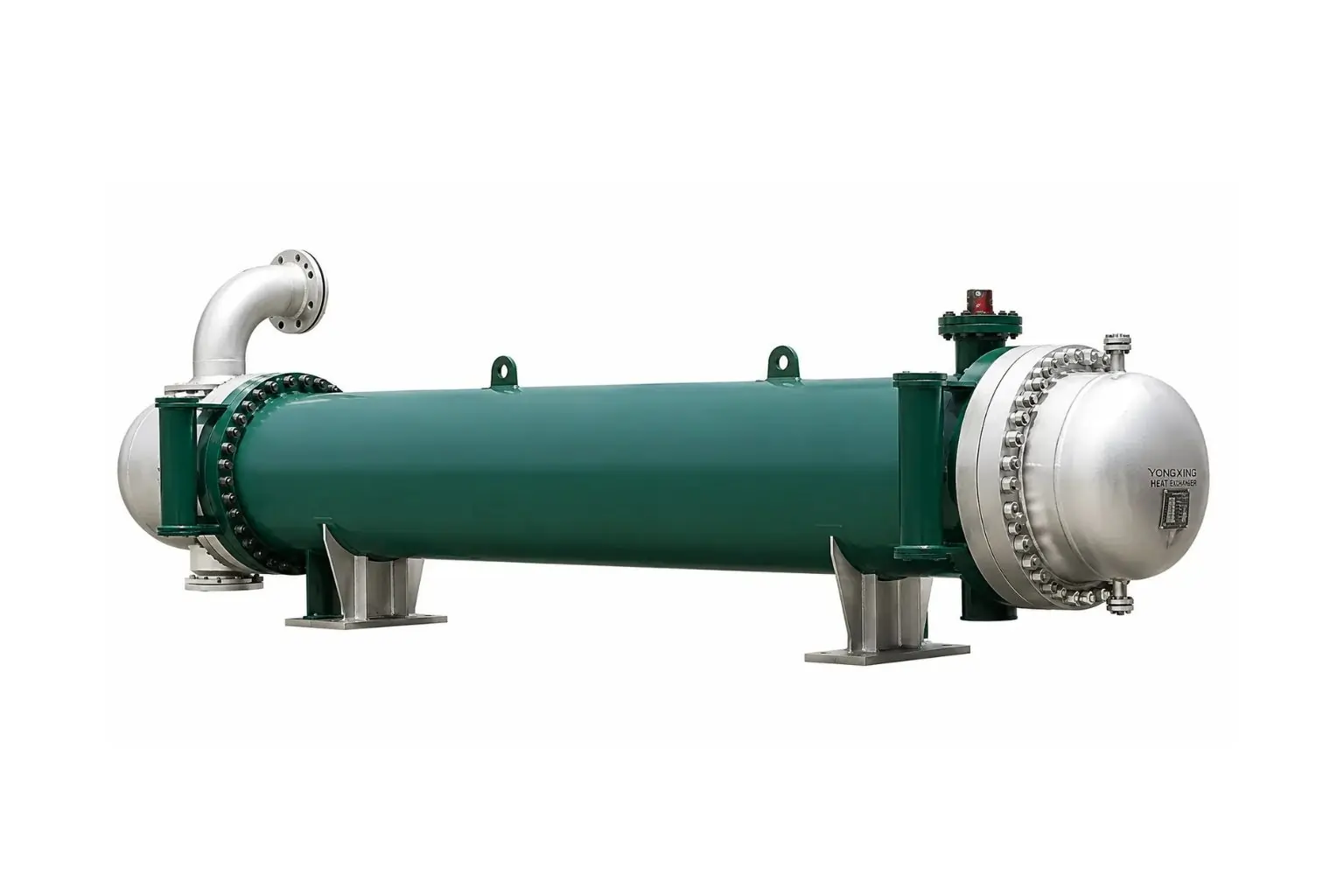
A floating head heat exchanger is a shell-and-tube design with one fixed tube sheet and one free tube sheet. The free end — called the floating head — moves axially as the bundle expands and contracts with temperature, eliminating thermal stress on the shell.
When cleaning is due, the shell cover is removed and the entire tube bundle slides out. Both ends of every tube are exposed for mechanical cleaning, inspection, or replacement — a capability no fixed tube sheet design offers.
As a leading floating head heat exchanger manufacturer in India, United Heat Exchangers fabricates TEMA S, T, and W configurations to TEMA-R standards — ASME U-Stamp certified, HTRI thermal rated, with a written performance guarantee on every unit.
Why Floating Head — The Engineering Case
Every shell-and-tube design faces two simultaneous challenges: differential thermal expansion and fouling access. The floating head is the only configuration that solves both — fully and at the same time.
Problem 1 — Differential Thermal Expansion
When tube-side fluid runs at 350°C and shell-side at 50°C, the tube bundle wants to grow. In a fixed tube sheet design, the shell resists — building axial stress that accumulates with every thermal cycle. The floating head eliminates this: the bundle grows, the floating assembly moves, and the shell carries zero axial load from thermal expansion.
Problem 2 — Fouling Fluid Access for Mechanical Cleaning
Crude oil, residue, amine, and heavy naphtha deposit coke, asphaltene, and scale that chemical cleaning alone cannot remove. Mechanical cleaning needs both tube ends exposed. A fixed tube sheet seals one end inside the shell. A floating head design pulls the entire bundle out — every tube end accessible, every tube cleanable or replaceable.
💡 The refinery standard: In crude distillation, vacuum distillation, and hydrocracker units, floating head exchangers are not a preference — they are the engineering requirement. Large temperature differentials plus highly fouling crude fractions make any other configuration unworkable over a full four-to-five-year turnaround cycle.
Anatomy — Every Component and What It Does
Floating Head Heat Exchanger — Cutaway Overview (TEMA S Configuration)

TEMA S cutaway — fixed tube sheet (left), floating tube sheet and bonnet (right, inside shell), segmental baffles, two-pass tube-side flow, removable shell cover
Shell
Cylindrical pressure vessel containing the shell-side fluid and tube bundle. Sized to TEMA standards. Material matched to shell-side fluid chemistry and operating pressure — carbon steel for standard service, stainless or alloy for corrosive duties.
Fixed Tube Sheet
The stationary tube sheet welded to the shell at the channel end. All tubes are expanded or welded here. Because the opposite end floats freely, this tube sheet carries no axial thermal stress — the key structural advantage over fixed tube sheet designs.
Floating Tube Sheet
The free tube sheet at the bundle's far end. Not welded to the shell — it floats inside, attached only to the tube bundle and bonnet. As temperature changes, it slides axially with zero mechanical resistance from the shell.
Floating Head Bonnet
Internal cover sealing the floating tube sheet on the process side. In TEMA S, a split backing ring clamps a dished bonnet to the floating tube sheet. Precision-machined mating surfaces maintain a reliable high-pressure seal through full thermal cycling.
Shell Cover
Removable flanged cover bolted to the shell at the floating head end. Removing it is the first step in bundle extraction — no cutting, no welding. This single bolted component is what makes turnaround maintenance practical in the field.
Stationary Channel
End compartment at the fixed tube sheet. A pass partition plate divides it into inlet and return compartments. The channel is bolted separately — removable for tube sheet and tube-end access without disturbing the shell or bundle.
Straight Tube Bundle
All tubes are straight — the defining maintenance advantage. After removing the channel and shell cover, both ends of every tube are accessible for mechanical cleaning, pressure testing, and individual tube replacement.
Segmental Baffles
Disc plates with a cut segment, spaced to direct shell-side fluid in crossflow across the tube bundle. Baffle spacing and cut percentage are HTRI-optimised for the heat transfer rate versus shell-side pressure drop of each specific service.
Impingement Protection
An impingement plate or rod bundle below the shell-side inlet nozzle protects the first tube row from erosion by high-velocity entering fluid. Required by TEMA above defined velocity limits and for two-phase inlet streams.
Tie Rods and Spacers
Longitudinal rods with precision-cut spacer tubes hold the entire baffle stack at the designed pitch. Without them, baffles migrate under flow forces — disrupting the crossflow pattern and degrading thermal performance over time.
How a Floating Head Heat Exchanger Works
The sequence below describes a standard two-pass TEMA S unit — the most common configuration in refinery service.
Tube-Side Fluid Enters
Enters the channel inlet nozzle, fills the first-pass compartment, and distributes into the inlet-pass tubes.
Travels First Pass
Flows the full shell length through inlet-pass tubes, exchanging heat through the tube walls toward the floating head end.
Reverses in Floating Head
The floating head bonnet redirects fluid from inlet-pass into return-pass tubes. The bonnet partition keeps the two passes isolated.
Returns Through Second Pass
Fluid travels back through return-pass tubes toward the fixed tube sheet — continuing to transfer heat the full length again.
Shell-Side Fluid Crosses
Shell-side fluid is directed by baffles in an S-shaped crossflow path across all tubes — continuously transferring heat to or from the tube side.
Bundle Floats Freely
Throughout operation, the floating tube sheet slides freely — absorbing all differential thermal expansion with no stress on any welded joint.
💡 Two passes — always the minimum. Every floating head design has at least two tube-side passes. Four, six, and eight passes are available by adding partition plates to both the channel and floating head bonnet — enabling tighter temperature approaches in close-approach heat recovery duties.
TEMA S, T, and W — Three Floating Head Configurations
TEMA defines three floating head designs. Each solves the same thermal expansion and cleaning problem — but with different sealing mechanisms, maintenance procedures, and pressure capabilities. United Heat Exchangers manufactures all three.
TEMA Type S — Split Backing Ring
The global refinery standardThe floating head bonnet is bolted to a split backing ring that clamps the floating tube sheet. Compact design — smaller shell diameter for a given tube count versus TEMA T. Bundle removal requires removing the shell cover, unbolting the split ring, then withdrawing the bundle.
- Most widely used floating head design in refinery service worldwide
- Handles high tube-side pressures and large temperature differentials
- Lower installed cost than TEMA T for equivalent tube count
- Split ring requires a precise torque sequence to maintain seal integrity
TEMA Type T — Pull-Through Bundle
Fastest bundle extractionThe floating head bonnet bolts directly to the floating tube sheet and is sized to clear the shell bore on extraction. Remove the shell cover and pull — the entire bundle slides out without any internal disassembly. The fastest maintenance access of any shell-and-tube design.
- No internal disassembly before bundle removal
- Specified for very high fouling services with frequent cleaning cycles
- Requires a larger shell diameter than TEMA S for the same tube count
- Higher fabricated cost — larger shell plus heavier floating head flange
TEMA Type W — Packing-Sealed
Simple construction, moderate pressureThe floating tube sheet extends beyond the shell and is sealed by a packed stuffing box. The packing absorbs thermal movement while maintaining a liquid seal. Simplest internal arrangement — no split ring, no internal bonnet bolting. Limited to moderate tube-side pressures.
- Lowest fabrication complexity of the three floating head types
- Packing requires periodic inspection and replacement
- Not suitable for toxic, lethal, or high-pressure services
- Good fit for moderate-pressure duties where bundle cleanability is the priority
💡 Which type fits your service? High-pressure, standard refinery fouling — TEMA S. Very high fouling rate, fastest turnaround — TEMA T. Moderate pressure, budget-conscious — TEMA W where pressure allows. United Heat Exchangers provides the type recommendation with technical rationale in every engineering proposal.
Design Specifications and Standards
Every floating head heat exchanger is custom-engineered to your process datasheet — thermally rated with HTRI Xchanger Suite, mechanically designed to TEMA, and pressure-certified to ASME BPVC Section VIII.
| Specification | Range / Options |
|---|---|
| Shell Inside Diameter | 200 NB (8 inch) to 2,500 mm — larger on enquiry |
| Shell Length | 1.5 m to 12.0 m; multi-shell trains for larger duties |
| Tube-Side Design Pressure | Full vacuum to 350 bar (TEMA S/T); moderate range for TEMA W packing seal |
| Shell-Side Design Pressure | Full vacuum to 150 bar standard; higher on enquiry |
| Design Temperature | -29°C to +650°C standard; cryogenic and ultra-high-temp alloy on enquiry |
| TEMA Floating Head Type | S (split ring), T (pull-through), W (packing-sealed) — all manufactured |
| Tube-Side Passes | 2, 4, 6, or 8 passes — partition plates in channel and floating head bonnet |
| Tube OD | 15.88 mm (5/8 inch) to 38.1 mm (1½ inch); custom on request |
| Tube Wall Thickness | BWG 10 to BWG 22; heavy-wall for HP and erosion-corrosion services |
| Tube Layout | 30° triangular, 60° rotated, 90° square, 45° rotated square — per TEMA and service |
| Baffle Type | Segmental, double segmental, triple segmental, NTIW for low-pressure-drop or vibration-sensitive service |
| Tube Material | Carbon steel, 304/316L/321/347/904L SS, duplex 2205, super duplex 2507, titanium Gr.2, CuNi, Hastelloy C-276, Inconel 625 |
| Tube-to-Tube Sheet Joint | Expanded, strength-welded, or expanded-plus-welded; full-penetration weld for lethal and special services |
| Design Code | TEMA-R / B / C; ASME BPVC Section VIII Div. 1 & 2; ASME Section IX; PED (Europe); IBR (India steam) |
| NDE | Radiography (spot or 100%), UT, MPI, LPT, PMI — per code and inspection class |
Material Selection Guide
Tube, tube sheet, shell, channel, and floating head components each require independent material decisions — driven by fluid chemistry, temperature, fouling nature, and required service life. Right selection at the design stage prevents premature failure.
Carbon Steel (SA-179 / SA-192)
Standard for clean hydrocarbons, steam, condensate, and cooling water. Most cost-effective for large surface areas. Corrosion allowance of 1.5–3.2 mm specified per fluid chemistry and required service life.
316L Stainless Steel
Selected for mildly corrosive fluids, amine solutions, and acidic aqueous streams. Low-carbon grade prevents sensitisation at weld heat-affected zones in aggressive service environments.
321 / 347 Stabilised Stainless
Titanium-stabilised (321) or niobium-stabilised (347) — specified for high-temperature service above 425°C where standard 304/316 sensitisation at weld zones would cause intergranular corrosion.
Duplex 2205
Twice the yield strength of 316L, with outstanding chloride stress corrosion cracking resistance. Specified for sour service, chloride-contaminated streams, seawater cooling, and offshore applications.
Super Duplex 2507
PREN above 40 — the recognised threshold for reliable seawater service. Specified for offshore produced water coolers, high-chloride brine, and duties where duplex 2205 provides insufficient pitting resistance.
Titanium Grade 2
Essentially immune to seawater corrosion and wet chlorine. The highest-performance option for aggressive marine and chemical service — where no other commercially practical material provides equivalent service life.
Hastelloy C-276 / Inconel 625
Nickel alloys for concentrated acids, wet chlorine gas, and mixed oxidising-reducing environments that defeat stainless steel. Both are fully weldable and available in tube, plate, and forging form.
Clad Tube Sheets
Carbon steel base with stainless, duplex, or Hastelloy weld-overlay or explosion-bonded cladding. Delivers alloy corrosion resistance at the process face — at a fraction of solid alloy forging cost.
Industries and Applications
| Industry | Typical Application | Why Floating Head Is Specified |
|---|---|---|
| Oil & Gas Refining | Crude preheat trains, atmospheric and vacuum overhead condensers, kerosene and diesel coolers, vacuum residue coolers | Crude and heavy fractions foul severely — mechanical cleaning is mandatory. Large temperature differentials in preheat trains require free thermal expansion. TEMA S is the industry default. |
| Hydroprocessing | Reactor feed/effluent exchangers in hydrotreaters, hydrocrackers, and catalytic reformers | Combines extreme temperature differentials (200°C+), high pressure (100+ bar), and ammonium salt fouling — all three simultaneously requiring floating head with full bundle pull. |
| Petrochemicals | Ethylene cracker quench oil coolers, pyrolysis gasoline coolers, styrene reactor feed exchangers | Pyrolysis streams contain polymerisation-prone dienes — tube fouling rates are high and mechanical cleaning is non-negotiable at every turnaround. |
| Gas Processing — Amine Units | Lean/rich amine heat exchangers in gas sweetening units | Rich amine deposits iron sulfide and heat-stable salts that chemical cleaning alone cannot remove. Mechanical cleaning of tube-side rich amine is standard practice at every amine plant turnaround. |
| LNG Plants | Feed gas coolers, nitrogen cycle exchangers, refrigerant interchangers, lean oil exchangers | Large temperature differentials in cryogenic service; some streams partially condense and foul tube surfaces during plant transients. |
| Power Generation | Fuel oil heaters, turbine lube oil coolers, closed cooling water exchangers where tube-side oil fouling requires periodic mechanical cleaning | Heavy fuel oil and turbine lube oil develop tube-side deposits that mechanical cleaning addresses — floating head provides the required access. |
| Fertilizer & Ammonia | Shift converter feed/effluent exchangers, CO₂ absorber lean/rich exchangers, urea solution coolers | Very high pressures in ammonia synthesis loops combined with CO₂ absorber fluid fouling — floating head handles both demands in a single shell. |
| Chemical Processing | Reactor feed preheaters, distillation column feed/bottoms exchangers, solvent recovery exchangers | Diverse fouling chemical streams with varying thermal differentials — floating head provides the conservative, reliable choice for high-value process duties. |
Floating Head Heat Exchangers for Every Demanding Process Service
From crude preheat trains to reactor feed/effluent units — TEMA-R, ASME U-Stamp certified, with full HTRI thermal guarantees and complete documentation. Free quote in 48 hours.
Request My Free Quote →Floating Head vs U-Tube vs Fixed Tube Sheet
Four factors determine the right configuration: temperature differential, tube-side fouling, operating pressure, and maintenance access requirement.
| Criterion | Floating Head | U-Tube | Fixed Tube Sheet |
|---|---|---|---|
| Thermal Expansion | Floating tube sheet moves freely — zero shell stress | U-bend absorbs all differential expansion | ⚠ Bellows required for large temperature differentials |
| Tube-Side Mechanical Cleaning | Full access — both tube ends exposed after bundle pull | Not possible — U-bend blocks mechanical tools | Both ends accessible — full mechanical cleaning |
| Individual Tube Replacement | Every tube individually replaceable | ⚠ Outer rows replaceable; inner rows plugged | Every tube individually replaceable |
| Maximum Operating Pressure | High — TEMA S and T handle very high pressures | Highest — single tube sheet, no floating seal | High — two fixed tube sheets, simple pressure boundary |
| Shell-Side Bundle Access | Complete bundle pull exposes shell interior | Bundle pulls out for shell interior access | Fixed bundle — chemical cleaning through nozzles only |
| Fabricated Cost | ⚠ Highest — precision floating head internals add cost | Lower than floating head — single tube sheet advantage | Lowest — no floating internals, no shell cover |
| Best Application | Fouling tube side requiring mechanical cleaning + large temperature differential | Clean tube side at high pressure and high temperature | Clean tube side, moderate temperature differential, standard service |
💡 One-sentence selection rule: Fouling tube side + large temperature differential = floating head. Clean tube side at extreme pressure and temperature = U-tube. Neither fouling nor differential expansion is serious = fixed tube sheet at lowest cost. United Heat Exchangers makes this recommendation before the order, not after.
Why United Heat Exchangers
Manufacturing a floating head heat exchanger that process plant operators and inspection authorities accept without reservation requires precision — particularly the floating head assembly, which must maintain a reliable high-pressure seal through decades of thermal cycling and repeated turnaround bundle pulls. United Heat Exchangers has delivered this precision consistently since 1989.
35+ Years — Floating Head Expertise
Every engineering lesson from every unit delivered since 1989 is embedded in our current design and fabrication practice. Floating head exchangers are a core product — not an occasional special job.
HTRI Thermal Design — Written Guarantee
Thermally rated using HTRI Xchanger Suite — correctly modelling the multi-pass tube-side, baffle geometry, impingement zone, and agreed fouling resistances. A written performance guarantee is issued with every unit.
ASME U-Stamp and R-Stamp
All pressure components manufactured to ASME BPVC Section VIII. All welds qualified per ASME Section IX. Both certifications independently audited — a non-negotiable requirement for refinery and process plant service internationally.
Floating Head Assembly Precision
Split ring, bonnet seating face, and floating tube sheet mating surfaces are machined to defined tolerances. Dimensional records are included in the documentation package for every TEMA S and T unit we deliver.
Complete Documentation — No Gaps
MTRs, radiography records, hydrostatic test certificates, TEMA data sheet, nozzle drawings, WPS/PQR records, and the ASME MDR — issued as a complete package before shipment, without follow-up requests.
Replacement Bundle Capability
Replacement bundles manufactured to the original bore pattern and nozzle layout — with options to upgrade tube material, change TEMA type, or re-rate for a new service. The shell need not be replaced simply because the bundle is worn.
Delivery and What's Included
What's Included with Every Floating Head Heat Exchanger Order
- Written HTRI thermal performance guarantee — rated for your process conditions, fouling resistances, and multi-pass arrangement; issued as a formal commitment
- ASME U-Stamp Manufacturer's Data Report (MDR) — signed by the Authorised Inspector, covering all pressure-containing components on both circuits
- Material certifications (MTRs) — mill test reports for all tubes, tube sheets, shell, channel, and floating head components; traceable to heat and lot number
- Weld procedure qualification records (WPS / PQR) — for all pressure welds including tube-to-tube-sheet joints, shell seams, nozzles, and floating head bonnet welds
- NDE records — radiography, UT, PMI, MPI or LPT as applicable to design code and inspection class
- Hydrostatic test certificates — tube side and shell side each tested to 1.5× design pressure; third-party witness available
- Floating head assembly dimensional inspection records — split ring and bonnet seating surface tolerances, tube sheet bore pattern verification for TEMA S and T designs
- TEMA data sheet — fully completed; tube sheet drilling layout; nozzle orientation and baffle arrangement drawings
- Operation and maintenance manual — bundle extraction procedure, floating head disassembly sequence, tube cleaning methods, inspection intervals, torque values, spare parts list
- Lifetime technical support — re-rating, replacement bundle, TEMA type conversion, and performance troubleshooting throughout every unit's service life
Get a Free Floating Head Heat Exchanger Quote in 48 Hours
Share your process fluid, flow rates, temperatures, design pressure, fouling nature, temperature differential, site conditions, and applicable codes. Our engineering team selects the right TEMA type, sizes the unit, and delivers a technical proposal within 48 hours.
Request My Free Quote →Frequently Asked Questions
What is a floating head heat exchanger?
A shell-and-tube heat exchanger with one fixed tube sheet and one free-floating tube sheet. The floating end moves axially as the bundle expands thermally — eliminating differential thermal stress. The entire bundle slides out of the shell for mechanical cleaning and tube inspection.
What is the difference between TEMA S, T, and W?
TEMA S uses a split backing ring to clamp the bonnet to the floating tube sheet — compact, high-pressure capable, the refinery standard. TEMA T bolts the bonnet directly to the floating tube sheet and pulls through the shell on extraction — fastest bundle removal but requires a larger shell. TEMA W seals with a packed stuffing box — simplest construction, limited to moderate pressures.
Why is the floating head the standard design for crude oil preheat trains?
Crude oil combines two demands simultaneously: large temperature differentials (300°C+ hot products against cold crude) that require free thermal expansion, and heavy fouling deposits that require mechanical tube cleaning at every turnaround. No other single-shell design handles both requirements. The floating head does — which is why it is the refinery industry's default specification.
Can the floating head type be changed when a replacement bundle is ordered?
Within constraints — yes. Changing TEMA S to T requires a larger shell bore, so a new shell is needed. Changing T to S is possible within the existing shell if the shell diameter is sufficient. United Heat Exchangers confirms compatibility as part of every replacement bundle enquiry at no additional engineering charge.
What is the maximum operating pressure for a floating head heat exchanger?
TEMA S and T designs handle tube-side pressures up to approximately 350 bar in standard configurations. TEMA W packing-sealed designs are limited to moderate pressures — typically below 20–30 bar. Shell-side pressure limits follow standard pressure vessel design rules regardless of floating head type.
Which tube-side services require a floating head rather than a U-tube or fixed tube sheet?
Any service where tube-side fouling cannot be fully resolved by chemical cleaning — crude oil, vacuum residue, rich amine, pyrolysis gasoline, coker fractionator bottoms, and streams depositing coke, asphaltene, iron sulfide, or ammonium salts. If mechanical cleaning is required at turnaround, the design must allow both tube ends to be accessed — which means floating head or fixed tube sheet with straight tubes, not U-tube.
Are United Heat Exchangers floating head heat exchangers ASME certified?
Yes. All pressure components are manufactured to ASME BPVC Section VIII Division 1 and U-Stamped. All welds are performed to ASME Section IX qualified procedures. United Heat Exchangers holds current ASME U-Stamp and R-Stamp Certificates of Authorization, independently audited by the Authorised Inspection Agency.
What is the delivery time for a floating head heat exchanger?
Standard TEMA S and T units in carbon steel or stainless steel deliver in 8–12 weeks from order confirmation and approved drawings. Alloy construction, large-diameter shells, and high-pressure or TEMA-R Class 1 units deliver in 12–20 weeks. Expedited turnaround schedules are available on request.
Author: Senthil Kumar, Technical Director — United Heat Exchangers Pvt. Ltd. | Last Updated: May 2026
Related Products