Author: Senthil Kumar, Technical Director | Updated: March 2026 | Read time: 13 min
Table of Contents
- What Is a Reflux Condenser?
- How Does a Reflux Condenser Work?
- Types of Reflux Condensers
- Design and Construction
- Materials and Construction Standards
- Industrial Applications
- How to Select the Right Reflux Condenser
- Performance and Troubleshooting
- Maintenance Best Practices
- Standards and Codes
- Why Choose United Heat Exchangers?
- Frequently Asked Questions
- Get a Free Quote in 48 Hours
What Is a Refluxer Condenser?
A refluxer condenser is a heat exchanger mounted directly at or above the top of a distillation column, reactor, or process vessel that partially or totally condenses the rising overhead vapor — returning the resulting liquid condensate (called reflux) back into the column by gravity, while allowing uncondensed vapor or non-condensable gases to exit as overhead product.
Unlike a conventional condenser that simply removes heat to produce a liquid product stream, the reflux condenser plays a dual role: it removes latent heat from the vapor and simultaneously controls the vapor-liquid composition at the top of the distillation system. The ratio of liquid returned to the column versus liquid withdrawn as product — known as the reflux ratio — is the primary lever for controlling separation sharpness and product purity.
💡 Simple analogy: Think of a reflux condenser as a controlled "raining" mechanism at the top of a distillation column. Vapor rising from below is cooled, turns to liquid, and rains back down — washing and enriching the ascending vapor with each pass. The more liquid you return, the purer your overhead product becomes, but the more energy you consume.
Reflux condensers are critical to the economics and product quality of virtually every distillation-based separation process — from crude oil refining to pharmaceutical synthesis. Getting the condenser design right directly determines column efficiency, energy consumption, and the purity of the final product.
How Does a Reflux Condenser Work?
The operating principle of a reflux condenser combines fundamental heat transfer with the thermodynamics of vapor-liquid equilibrium. Understanding each stage of the process is essential to specifying the right unit for your column.
Vapor Rises from Column
Hot, enriched vapor from the top tray or packing of the distillation column flows upward into the condenser shell or tube side, carrying a mixture of the light and heavy components at or near the dew point.
Heat Transfer & Condensation
Coolant — typically cooling water, chilled water, or a process fluid — circulates on the opposing side of the heat transfer surface. Latent heat is removed from the vapor, which condenses to liquid on the tube wall or surface.
Condensate Drains as Reflux
In a vertical unit, liquid condensate drains downward by gravity back into the column top — this is the reflux stream. In horizontal units, condensate collects in a reflux drum and is pumped back to the column.
Overhead Product Exits
In a total condenser, all condensate is split between reflux return and distillate product withdrawal. In a partial condenser, uncondensed vapor exits directly as gaseous overhead product.
The Reflux Ratio — The Key Operating Variable
The reflux ratio (R) is defined as the volumetric or molar flow of reflux liquid returned to the column divided by the overhead distillate product flow withdrawn:
R = L / D where L = reflux flow returned to column | D = distillate product flow withdrawn
Higher R → Better separation, higher product purity, but greater condenser duty and operating cost.
Lower R → Less energy use, but reduced separation — more column trays required to achieve the same purity.
Optimum R → Typically set at 1.2 to 1.5 × the minimum reflux ratio for most industrial columns.
| Reflux Ratio Range | Separation Quality | Condenser Duty | Typical Application |
|---|---|---|---|
| R < 1 | Low — limited enrichment | Minimum | Rough separation, pre-fractionation |
| R = 1–3 | Moderate — standard commercial | Moderate | Petroleum fractionators, solvent recovery |
| R = 3–10 | High — close-boiling separations | High | Cryogenic air separation, fine chemicals |
| Total Reflux (R = ∞) | Maximum theoretically possible | Maximum | Column commissioning, startup, troubleshooting |
Types of Reflux Condensers
Reflux condensers are classified by orientation, condensation mode, and whether they produce a total or partial condensate. Selecting the correct type is the most important engineering decision for your column overhead system.
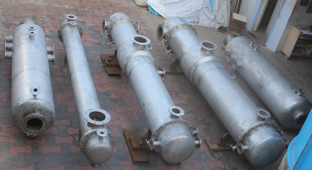
1. Vertical Shell-and-Tube Reflux Condenser (Overhead Type)
The most widely used configuration in industrial distillation. The unit is mounted vertically above the column top, with vapor entering the shell or tube side from below, condensate draining back down into the column by gravity, and coolant circulating on the opposing side.
- Gravity-return reflux — no reflux drum or pump required, simplifying the overhead system and reducing capital cost
- Self-draining — condensate cannot accumulate and flood the column top nozzle under normal operation
- Compact plot footprint — sits directly on the column, eliminating the structural steel for a separate elevated reflux drum
- Preferred for clean, low-fouling services where tube-side cleaning access is not a frequent requirement
- Standard for columns in petroleum refining, petrochemicals, and solvent recovery
2. Horizontal Shell-and-Tube Reflux Condenser with Reflux Drum
The condenser is mounted horizontally at grade or on a structural platform, with condensate collected in a separate reflux drum (accumulator) and returned to the column top by a reflux pump. This is the dominant configuration for large-capacity columns in refineries and gas plants.
- Easy tube-side bundle access for mechanical cleaning — preferred for fouling services such as crude overhead systems and polymerizing streams
- Large condensate inventory in the reflux drum provides stable level control and surge capacity during process disturbances
- Allows split reflux and distillate draws — both liquid and vapor products can be withdrawn from the drum independently
- Better suited for high vapor loads — the horizontal shell provides a large vapor inlet cross-section that reduces inlet velocity and minimizes entrainment
- Preferred for vacuum column overhead services (atmospheric and vacuum crude units) and large ethylene / propylene fractionators
3. Total Condenser
Condenses the entire overhead vapor stream to liquid. The condensate is split between reflux returned to the column and distillate withdrawn as product. All overhead product leaves the system as a liquid stream.
- Used when the overhead product is required as a liquid distillate — gasoline, naphtha, solvent, or liquid chemical product
- Simpler control scheme — a single level controller manages the reflux drum level and sets the reflux and distillate split
- Non-condensable gas vent required to prevent pressure build-up from inerts accumulating in the drum
4. Partial Condenser
Condenses only a fraction of the overhead vapor — returning condensate as reflux while the remaining vapor exits as a gaseous distillate product. A partial condenser also performs one theoretical equilibrium stage of separation, improving overall column efficiency.
- Used when the overhead product is required as a vapor or gas — hydrogen-rich streams, light hydrocarbon gases, reactor vent gases
- Provides an additional theoretical separation stage at no extra column height
- Coolant temperature must be carefully controlled to maintain the desired vapor-liquid split at the condenser outlet
- Common in gas plant deethanizers, demethanizers, and steam cracker product recovery columns
5. Air-Cooled (Fin-Fan) Reflux Condenser
Uses ambient air as the cooling medium in place of cooling water, passing overhead vapor through finned tube bundles cooled by forced-draft or induced-draft fans. Eliminates cooling water consumption entirely.
- Zero cooling water consumption — ideal for water-scarce locations and remote processing facilities
- Designed to API 661 for petroleum and petrochemical services
- Condensing temperature limited by ambient air temperature — unsuitable for low-boiling-point products requiring sub-ambient cooling
- Common on crude distillation units, gas sweetening columns, and NGL fractionators in arid or offshore environments
Need a Reflux Condenser for Your Distillation System?
Share your column overhead conditions — vapor flow, dew point, reflux ratio, fouling tendency, and design code — and our thermal engineering team will size and configure the right unit within 48 hours.
Request My Free Quote →Design and Construction
Shell-and-Tube Configuration
The overwhelming majority of industrial reflux condensers are shell-and-tube heat exchangers, selected for their ability to handle the full range of operating pressures, temperatures, and fluid combinations encountered in distillation overhead service. Key configuration decisions include:
| Design Parameter | Options | Selection Basis |
|---|---|---|
| Vapor Side Location | Shell side (most common) or tube side | Shell side preferred for large vapor volumes — lower pressure drop and more condensation surface; tube side used for corrosive or high-pressure vapors |
| Orientation | Vertical or horizontal | Vertical for gravity reflux return; horizontal for large-capacity units with reflux drums and better cleaning access |
| Head Type (TEMA) | Fixed tubesheet, U-tube, floating head | U-tube for high-temperature differential; floating head (AES/AEW) for high fouling services requiring full bundle pull; fixed tubesheet for clean, low-differential services |
| Number of Passes | Single tube pass or multi-pass | Single pass preferred for low pressure drop coolant circuits; multi-pass to increase coolant velocity and heat transfer coefficient |
| Baffle Type | Segmental, double-segmental, rod baffles, no-tubes-in-window (NTIW) | Double-segmental or rod baffles to reduce shell-side pressure drop in vacuum overhead services; NTIW to eliminate tube vibration on long unsupported spans |
| Condenser Duty Type | Total or partial condensation | Total: full vapor condensed to liquid for liquid distillate product. Partial: controlled partial condensation retaining vapor overhead product and contributing one theoretical separation stage |
Condensate Drainage Design
In vertical gravity-return units, the condensate drain path from the condenser back into the column is a critical design element. The drain nozzle must be sized to prevent liquid backup that would flood the condenser shell and reduce the effective heat transfer area, while also maintaining a liquid seal that prevents vapor from bypassing the condenser through the drain line.
- A separate vapor inlet and liquid drain nozzle on the column top nozzle prevents condensate from blocking incoming vapor flow
- The drain line is sized for gravity flow at maximum reflux — typically 10–20% of the shell diameter as a minimum drain nozzle bore
- Sealing legs or U-bends are incorporated where vapor breakthrough via the drain line must be prevented
Vacuum Service Considerations
Many distillation columns — particularly in refining (atmospheric and vacuum crude units) and pharmaceutical operations — operate at sub-atmospheric pressure. Reflux condensers for vacuum service require additional design attention:
- Very low shell-side pressure drop is critical — even a small pressure drop across the condenser is a significant fraction of the absolute column operating pressure and directly degrades column performance
- Double-segmental baffles, rod baffles, or no-baffle designs are used to minimize shell-side ΔP
- Shell wall thickness is designed for full external pressure (vacuum collapse) per ASME Section VIII, in addition to internal design pressure
- Large shell diameters are common because low-pressure vapor has a very high specific volume, requiring larger flow cross-sections to keep velocities within acceptable limits
Materials and Construction Standards
Material selection for reflux condensers is driven by the composition of the overhead vapor stream, the cooling medium, the operating pressure and temperature, and the expected service life. Overhead streams in refining and chemical service frequently contain corrosive species — chlorides, hydrogen chloride, hydrogen sulfide, organic acids, and ammonia — making correct material selection critical to service life and safety.
| Material | Common Grade | Best For | Key Limitation |
|---|---|---|---|
| Carbon Steel | ASME SA-516 Gr. 70 (shell); SA-179 (tubes) | Clean hydrocarbons, non-corrosive overhead streams, general process service | Susceptible to corrosion from chlorides, H₂S, and organic acids at elevated temperature |
| Stainless Steel 304 / 316L | ASME SA-240 / SA-213 TP316L | Mildly corrosive overhead vapors, pharmaceutical and food distillation, solvent recovery | Susceptible to chloride stress corrosion cracking above 60°C; 316L preferred over 304 for chloride environments |
| Duplex Stainless Steel 2205 | UNS S31803 / S32205 | Chloride-containing overhead streams, seawater-cooled units, sour hydrocarbon service | Requires careful welding qualification; embrittlement risk above 300°C |
| Copper-Nickel 90/10 | ASTM B111 C70600 | Seawater cooling circuits, marine overhead condensers | Not suitable for ammonia, acetylene, or sulfur-containing streams |
| Titanium Grade 2 | ASTM B338 | Aggressive chloride environments, seawater cooling, highly corrosive overhead streams | High cost; not suitable above 315°C; requires specialist welding |
| Alloy 825 / Incoloy | UNS N08825 | Highly corrosive acid service, wet H₂S environments with elevated chloride | High cost; typically specified only when lower alloys are inadequate |
| Hastelloy C-276 | UNS N10276 | Hydrochloric acid overhead streams, chlorinated solvent distillation, highly oxidizing acids | Very high cost; reserved for extremely corrosive service where all other alloys fail |
⚠ Overhead Corrosion Warning: Crude distillation overhead streams are among the most corrosive environments in refining — containing HCl formed by hydrolysis of chloride salts, H₂S, CO₂, and water. Tube material selection must account for under-deposit corrosion, dew-point acid attack, and erosion-corrosion at the vapor inlet nozzle. Our engineering team provides full corrosion analysis as part of the design process.
Construction Standards
- ASME BPVC Section VIII Div. 1 & 2 — All pressure-containing components designed, fabricated, inspected, and U-Stamped
- ASME Section IX — All pressure weld procedures and welder performance qualifications
- TEMA Class R / B / C — Shell-and-tube tolerances, fabrication practices, and minimum thicknesses per service class
- API 660 — Enhanced specification for petroleum and petrochemical shell-and-tube exchangers where specified by the project
- NACE MR0175 / ISO 15156 — Material qualification for sour service (H₂S-containing) overhead streams in oil and gas applications
- PED 2014/68/EU / IS 2825 — European Pressure Equipment Directive and Indian Standard compliance for international and domestic projects
Industrial Applications of Reflux Condensers
Reflux condensers are the thermal heart of every distillation-based separation process. If vapor rises, enriches, and must be returned as liquid to drive separation — a reflux condenser is doing the work.
| Industry | Column / Process | Overhead Product | Condenser Type |
|---|---|---|---|
| Oil Refining | Atmospheric crude distillation unit (CDU) | Naphtha / light straight-run gasoline | Horizontal shell-and-tube with reflux drum |
| Oil Refining | Vacuum distillation unit (VDU) | Light vacuum gas oil (LVGO) | Horizontal, large-diameter, low-ΔP baffle design |
| Gas Processing | Deethanizer / demethanizer columns | Ethane / methane gas product | Partial condenser, chilled water or refrigerant cooled |
| Gas Processing | NGL fractionators (depropanizer, debutanizer) | Propane / butane liquid product | Air-cooled (fin-fan) or water-cooled total condenser |
| Petrochemicals | Ethylene / propylene splitter | Polymer-grade ethylene or propylene | High-reflux-ratio shell-and-tube, refrigerant cooled |
| Petrochemicals | Aromatics extraction (benzene, toluene, xylene) | Benzene / toluene distillate | Vertical shell-and-tube, cooling water service |
| Chemical Manufacturing | Methanol, acetic acid, solvent purification columns | Purified solvent or chemical product | Vertical or horizontal shell-and-tube, stainless steel |
| Pharmaceutical | API synthesis reactors, solvent recovery stills | Recovered solvent (ethanol, acetone, IPA) | Vertical glass-lined or SS316L, cGMP-compliant design |
| Food & Beverage | Alcohol distillation columns (whisky, ethanol, spirits) | Rectified alcohol spirit | Copper or stainless steel vertical condenser |
| Specialty Chemicals | Essential oil distillation, fragrance processing | Essential oil fraction | Small-scale vertical shell-and-tube or coil-in-shell |
Reflux Condensers for Every Industry
From refinery overhead systems handling thousands of tons per day to pharmaceutical stills requiring cGMP compliance — United Heat Exchangers designs and fabricates reflux condensers for every scale and specification.
Talk to Our Engineers Today →How to Select the Right Reflux Condenser
Selecting a reflux condenser requires matching the design to your column overhead hydraulics, product requirements, fouling tendency, plot constraints, and cooling medium availability. Answer these key questions first.
Question 1 — What Is the Required Overhead Product Phase?
- Liquid distillate required → Total condenser — condenses all overhead vapor; product withdrawn as liquid from reflux drum
- Vapor or gas product required → Partial condenser — condenses only the reflux fraction; overhead product exits as vapor
- Both liquid and vapor products required → Partial condenser with sub-cooled reflux return, or total condenser with a vapor draw from the reflux drum
Question 2 — What Is the Vapor Load and Column Pressure?
- Atmospheric or above-atmospheric pressure, moderate vapor load → Vertical shell-and-tube with gravity reflux return — simplest and most economical configuration
- Vacuum service or high vapor volume → Horizontal shell-and-tube with low-ΔP baffle design and reflux drum — manages high specific-volume vapor flows and minimizes pressure drop penalty
- Very large capacity (refinery scale) → Horizontal multi-shell arrangement with shared reflux drum and pump system
Question 3 — What Is the Fouling Tendency?
- Clean service (light hydrocarbons, solvents, pure chemicals) → Fixed tubesheet or U-tube design; infrequent cleaning; lower capital cost
- Moderate fouling (crude overhead, organic-laden streams) → Removable bundle (floating head TEMA AES / AEW); tube-side cleaning access without removing bundle from shell
- Heavy fouling or polymerizing streams → Full floating-head pull-through bundle (TEMA T); complete bundle extraction for external cleaning or retubing
Question 4 — What Cooling Medium Is Available?
- Cooling water available → Shell-and-tube with water on tube side — most efficient and cost-effective for most industrial applications
- No cooling water / water-scarce site → Air-cooled (fin-fan) reflux condenser; zero water consumption; size for hottest ambient temperature expected
- Sub-ambient condensing temperature required → Chilled water or refrigerant-cooled shell-and-tube; essential for demethanizers, ethylene splitters, and cryogenic separations
- Process-fluid cooled → Feed-effluent exchange condenser; recovers overhead condensation heat into the column feed, improving overall process energy efficiency
✅ Design Tip: Always add a 10–20% surface area margin over your calculated condenser duty. Fouling accumulates on tube surfaces, cooling water temperature rises in summer, and column feed rates often increase beyond initial design capacity within 3–5 years of operation. An adequate area margin avoids expensive re-rating or replacement in the near term.
Performance and Troubleshooting
Reflux condenser performance directly affects distillation column stability and product purity. Most operational problems can be diagnosed by monitoring a small set of key process indicators.
| Symptom | Likely Cause | Diagnostic Check | Corrective Action |
|---|---|---|---|
| Overhead product off-spec (heavy component in distillate) | Insufficient condensation — low reflux return rate | Check condenser duty vs. design; coolant inlet temperature and flow rate | Increase coolant flow; clean fouled tubes; verify reflux control valve is fully open |
| Column pressure rising above setpoint | Non-condensable gas accumulation in condenser shell or reflux drum; reduced condensation rate | Check vent line for blockage; monitor non-condensable vent flow | Open vent to flare or vacuum system; clean vent line; purge inerts from shell side |
| Reduced heat transfer (rising outlet temperature with same coolant flow) | Tube fouling — scale, deposits, biological growth on tube walls | Compare overall heat transfer coefficient U against initial clean value; calculate fouling resistance | Schedule mechanical or chemical tube cleaning; improve cooling water treatment |
| Flooding / liquid backup into column | Condenser drain nozzle undersized; condensate drain line partially blocked | Check differential pressure across condenser; inspect drain line for liquid accumulation | Clear drain line obstruction; verify drain line sizing per design flow |
| Coolant-side pressure drop rising | Tube-side fouling narrowing effective flow area | Compare current ΔP against design basis; inspect tubes if accessible | Hydro-blast or chemical clean tube side; review cooling water quality and treatment regime |
| Tube leaks / cross-contamination | Corrosion pitting, erosion at inlet nozzle, thermal fatigue at tube-to-tubesheet joint | Eddy current or IRIS tube inspection; hydrostatic pressure test | Plug failed tubes (up to 10% without retubing); retube if failures are widespread; review material selection for service conditions |
Maintenance Best Practices
A well-maintained reflux condenser delivers consistent separation performance, protects product quality, and avoids unplanned column shutdowns. The following maintenance program covers the most critical activities.
Routine Monitoring (Continuous / Daily)
- Monitor coolant inlet and outlet temperature — rising outlet temperature at constant flow signals fouling accumulation
- Track shell-side and tube-side differential pressure — rising ΔP indicates fouling or partial blockage
- Verify reflux drum level control is stable — erratic level indicates condensation rate changes or coolant flow problems
- Check non-condensable vent flow and pressure — increasing column pressure signals inert accumulation
Periodic Cleaning (Frequency Based on Fouling Rate)
- Clean hydrocarbon or solvent services: Every 2–5 years during planned turnaround
- Crude overhead or fouling services: Every 12–24 months; high-pressure water lance or chemical circulation per deposit type
- Cooling water side: Every 6–18 months; hydro-blast scale and biological deposits; inspect tubes for pitting
- Air-cooled units: Clean fin surfaces annually with water washing or steam to remove dust, debris, and hydrocarbons
Inspection at Turnaround
- Eddy current or IRIS (Internal Rotary Inspection System) testing of tube bundle — detects wall thinning, pitting, and cracking not visible externally
- Inspect inlet nozzle and impingement plate for erosion from high-velocity vapor entry
- Examine tube-to-tubesheet joints for corrosion-fatigue cracking and joint separation
- Replace all channel cover, shell cover, and flanged-joint gaskets at each turnaround opening — never re-use compression gaskets
- Verify reflux control valve seat and trim condition — valve degradation directly affects reflux ratio accuracy and product purity
Standards and Codes
United Heat Exchangers designs and fabricates reflux condensers in full compliance with the applicable codes for each project and jurisdiction. All certifications are current and maintained under our ISO 9001:2015 quality management system.
| Code / Standard | Scope | Applicability to Reflux Condensers |
|---|---|---|
| ASME BPVC Section VIII Div. 1 & 2 | Pressure vessel design, fabrication, inspection, testing, and U-Stamp certification | All reflux condenser shells, channels, heads, nozzles, and pressure-containing components |
| ASME BPVC Section IX | Welding procedure and welder performance qualification | All pressure welds in condenser fabrication |
| TEMA Class R / B / C | Shell-and-tube heat exchanger construction tolerances, tube bundle design, and mechanical practices | Class R for refinery and petrochemical service; Class B for chemical process; Class C for general commercial service |
| API 660 | Shell-and-tube heat exchangers for petroleum, petrochemical, and natural gas industries | Enhanced specification layer applied over TEMA and ASME for refinery and gas plant overhead systems |
| API 661 | Air-cooled heat exchangers for petroleum, petrochemical, and gas industries | Applies to air-cooled (fin-fan) reflux condenser designs |
| ASME B31.3 Process Piping | Design of process piping connected to reflux condensers | Reflux return lines, overhead vapor inlet piping, and distillate product lines |
| NACE MR0175 / ISO 15156 | Material qualification for H₂S sour service | Reflux condensers in crude overhead, gas plant, and upstream oil & gas applications containing H₂S |
| PED 2014/68/EU / IS 2825 | European Pressure Equipment Directive and Indian Standard for pressure vessels | Available for international and domestic project compliance as required |
Why Choose United Heat Exchangers for Your Reflux Condenser?
- 35+ years of manufacturing experience — reflux condensers delivered to oil refineries, petrochemical complexes, pharmaceutical plants, and chemical manufacturers across India and internationally
- ASME U-Stamp & R-Stamp certified fabrication facility with full documentation package for regulatory and insurance compliance
- TEMA Class R, B, and C capability — matching the construction standard to the service severity and project specification
- API 660 and API 661 licensed for petroleum and petrochemical reflux condenser applications
- In-house thermal and mechanical design using HTRI, HTFS, and ASPEN EDR software — complete performance guarantee with every unit
- Full corrosion engineering support — material selection review for overhead vapor streams including HCl, H₂S, CO₂, ammonia, chlorinated solvents, and organic acids
- Both surface-type and air-cooled designs available — including partial condensers, total condensers, and spray-augmented configurations
- Fast-track delivery: Standard designs in 4–8 weeks; complex engineered units in 8–16 weeks
- Lifetime technical support — OEM documentation, performance monitoring guidance, and troubleshooting throughout the equipment lifespan
- Free feasibility study and budgetary quote within 48 hours of receiving your process data sheet
Frequently Asked Questions About Reflux Condensers
1. What is a reflux condenser?
A reflux condenser is a heat exchanger mounted at or above the top of a distillation column or reactor that partially or totally condenses overhead vapor, returning the liquid condensate (reflux) back into the column by gravity while allowing uncondensed vapor to exit as overhead product. It controls both the temperature profile and the vapor-liquid composition at the column top — and is the primary means of controlling overhead product purity in any distillation system.
2. What is the difference between a total condenser and a partial condenser?
A total condenser condenses the entire overhead vapor to liquid. The condensate is split between reflux returned to the column and liquid distillate withdrawn as product — all overhead product leaves as a liquid. A partial condenser condenses only a portion of the vapor: condensate is returned as reflux and the remaining uncondensed vapor exits as a gaseous overhead product. Partial condensers also contribute one theoretical equilibrium stage of separation, making them more thermally efficient for gas-product overhead systems.
3. Why is a reflux condenser installed vertically?
Vertical installation allows condensate to drain back into the column top by gravity — eliminating the need for a separate reflux drum, reflux pump, and associated instrumentation. Vapor rises through the condenser, condenses on cooled surfaces, and liquid flows downward naturally. Horizontal installations are used for large-capacity units where tube-bundle cleaning access is a priority, or where plot height constraints prevent vertical installation — but they require a reflux drum and pump to return liquid to the column.
4. What is the reflux ratio and how does it affect product purity?
The reflux ratio (R = L/D) is the ratio of reflux liquid returned to the column versus distillate product withdrawn. A higher reflux ratio returns more liquid to the column, providing more vapor-liquid contact stages and improving separation sharpness and product purity. However, a higher R also increases condenser duty, reboiler duty, and overall energy consumption. The optimum industrial reflux ratio is typically set at 1.2 to 1.5 times the minimum reflux ratio — the point where separation quality is adequate and energy cost is minimized.
5. What industries use reflux condensers?
Reflux condensers are used wherever distillation-based separation is performed: oil refining (crude distillation, vacuum units, naphtha splitters), gas processing (demethanizers, deethanizers, NGL fractionators), petrochemicals (ethylene and propylene splitters, aromatics recovery), chemical manufacturing (methanol, acetic acid, solvent purification), pharmaceutical synthesis and solvent recovery, food and beverage (alcohol distillation), and specialty chemicals and fragrance processing.
6. What causes reflux condenser fouling and how can it be prevented?
Common fouling causes include scale deposition from cooling water chemistry (calcium carbonate, calcium sulfate), iron oxide deposits from corrosion products in the overhead stream, polymerization of reactive hydrocarbons on hot tube surfaces, and biological fouling in open cooling water circuits. Prevention involves maintaining correct cooling water chemistry and biocide treatment, controlling overhead stream pH and corrosion inhibitor injection, and designing tube-side velocity above 1.5 m/s to minimize deposit adhesion. Regular inspection and cleaning on a fouling-rate-based schedule is essential.
7. What information is needed to get a reflux condenser quote?
Provide: (1) Overhead vapor composition and flow rate, (2) Vapor inlet temperature and dew point, (3) Required condensing temperature and reflux ratio, (4) Coolant type, inlet temperature, and available flow, (5) Operating and design pressures, (6) Column operating pressure (especially if vacuum service), (7) Fouling tendency and required tube-bundle access, (8) Applicable design code and TEMA class. Our engineers will complete the thermal sizing, material selection, and mechanical design — and deliver budgetary pricing within 48 hours.
8. Are United Heat Exchangers reflux condensers ASME certified?
Yes. All reflux condensers are designed, fabricated, inspected, and stamped per ASME Boiler & Pressure Vessel Code Section VIII Division 1 and 2. United Heat Exchangers holds current ASME U-Stamp and R-Stamp certifications and complies with TEMA, API 660 / 661, NACE MR0175, PED 2014/68/EU, IS 2825, and other applicable international codes as required by each project specification.
Get Your Free Reflux Condenser Quote in 48 Hours
Share your column overhead specifications and our applications engineering team will recommend the right type, size, material, and design standard — backed by 35+ years of distillation equipment experience and full ASME certification.
Request My Free Quote →Author: Senthil Kumar, Technical Director — United Heat Exchangers Pvt. Ltd. | Published: March 2024 | Last Updated: March 2026