Author: Senthil Kumar, Technical Director | Updated: May 2026
Table of Contents
- What Is a Flash Tank?
- How a Flash Tank Works
- Types of Flash Tanks
- Key Components Explained
- How to Size a Flash Tank: Formulas and Rules
- Design Specifications and Standards
- Material Selection Guide
- Industries and Applications
- How to Select the Right Flash Tank
- System Benefits of a Correctly Designed Flash Tank
- Why United Heat Exchangers
- Delivery and What's Included
- Frequently Asked Questions
- Request a Free Quote
What Is a Flash Tank?
A flash tank — also called a flash vessel, flash drum, or flash steam recovery vessel — is an ASME-certified pressure vessel that separates the steam liberated when high-pressure condensate is discharged into a lower-pressure zone. When hot, pressurised condensate undergoes a sudden pressure drop as it enters the flash tank, a portion of it instantly vaporises — a phenomenon called flash steam. The flash tank provides the volume and geometry to separate this flash steam cleanly from the residual liquid condensate, allowing each stream to be routed to its respective destination in the steam and condensate system.
Without a correctly designed flash tank, flash steam is either lost to atmosphere through condensate drain systems — a direct and quantifiable energy waste — or it contaminates the condensate return line with two-phase flow, causing waterhammer, erratic trap operation, and premature failure of condensate pumps and steam traps. In a well-designed steam system, the flash tank is the component that converts what would otherwise be a waste stream into a usable low-pressure steam supply.
As a certified flash tank manufacturer in India, United Heat Exchangers is a manufacturer and designer of flash tanks that are used for a variety of purposes, including recovering condensate, venting process vessels, and performing multi-stage flash evaporation — serving power generation, chemical processing, pharmaceutical, food and beverage, and textile industries. Every flash tank is ASME Section VIII U-Stamp certified, hydraulically tested, and supplied with complete pressure vessel documentation.
How a Flash Tank Works
A flash tank performs a thermodynamic separation the moment condensate enters it: the sudden pressure drop forces a portion of the liquid to instantly vaporise, and the vessel's geometry and volume allow the two resulting phases — flash steam and residual condensate — to separate cleanly before each exits through its respective nozzle.
High-Pressure Condensate Enters
Hot condensate at high pressure — from steam traps, boiler blowdown, or process vessels — enters the flash tank through the inlet connection, typically positioned tangentially to induce a swirling motion that aids separation.
Pressure Drop Triggers Flash
As condensate enters the lower-pressure flash tank, its saturation temperature drops instantly. Since it is above saturation temperature at the new pressure, a fraction of the liquid immediately vaporises — producing flash steam. The remaining liquid drops to the new saturation temperature.
Steam and Liquid Separate
The vapour phase rises through the vessel while liquid settles to the bottom by gravity. The flash tank's diameter is sized so that the upward vapour velocity is low enough that liquid droplets are not entrained and carried into the steam outlet — achieving dry steam separation.
Flash Steam Exits to Low-Pressure Header
Dry flash steam leaves from the top outlet and enters a low-pressure steam header — supplying LP heating coils, deaerators, shell-and-tube preheaters, or low-pressure process equipment without any additional boiler fuel cost.
Residual Condensate Returns
The remaining liquid condensate — cooled to the saturation temperature of the flash tank pressure — is pumped back to the boiler feedwater tank for reuse after leaving through the bottom outlet and traveling to the condensate return system or drain.
💡 The pressure cooker analogy: When you open the lid of a pressure cooker rapidly, steam escapes violently — that is uncontrolled flash. A flash tank performs the same thermodynamic event but in a controlled vessel that captures the steam and directs it usefully. The vessel's sizing determines whether the steam exits dry and usable, or wet and contaminated with liquid carryover that will damage downstream equipment. An undersized flash tank produces wet, entrained steam; an oversized one wastes capital. Correct sizing is the engineering task, and it starts with knowing your inlet pressure, flash tank pressure, and condensate flow rate.
Types of Flash Tanks
Flash tanks are classified by their operating function, pressure configuration, and physical orientation. Selecting the correct type is determined by where the vessel sits in the steam and condensate system and what it is recovering — condensate flash steam, boiler blowdown, or multi-stage process flash.
Condensate Flash Tank
Steam trap discharge recovery — the most common industrial configurationReceives condensate discharged from high-pressure steam traps and allows flash steam to be recovered at a lower header pressure. The most widely installed type in industrial steam systems — found in every facility with a high-pressure and low-pressure steam distribution network.
- Recovers flash steam that would otherwise be vented to atmosphere through trap discharge lines
- Supplies LP steam header without additional boiler load — directly reducing fuel consumption per unit of useful heat delivered
- Tangential inlet recommended to reduce liquid entrainment and improve separation efficiency
- Liquid level control on the condensate outlet is essential to prevent steam blow-through into the condensate return line
- Internal demister pad optional for installations where inlet quality is variable or dryness of flash steam output is critical
Boiler Blowdown Flash Tank
TDS control blowdown recovery — heat and water reclaim from boiler blowdownReceives continuous or intermittent blowdown from the boiler drum — hot water at boiler operating pressure discharged to control dissolved solids concentration in the boiler water. The flash tank separates usable low-pressure steam from the blowdown stream and cools the residual blowdown water before it enters the drain or a heat recovery heat exchanger.
- Recovers steam from a stream that would otherwise represent a 100% energy loss to drain
- Flash steam typically fed to the deaerator — recovering both heat and distilled-quality feedwater
- Residual blowdown exits at flash tank saturation temperature — further cooled in a blowdown cooler before drain to meet effluent temperature regulations
- Sized for the blowdown rate, boiler operating pressure, and flash tank design pressure — typically atmospheric to 2 bar(g)
- For the majority of boiler water chemistries, carbon steel construction is suitable; stainless steel is recommended in situations when blowdown pH or chemistry are harsh.
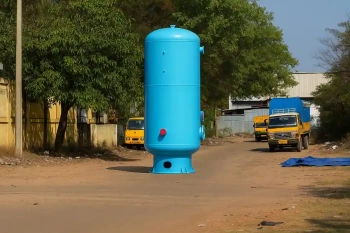
Vertical Flash Tank
Gravity-aided separation — standard configuration for steam systemsCylindrical vessel oriented vertically. The vertical orientation aligns gravity with the desired separation direction — vapour rises, liquid falls — making it the natural and preferred configuration for flash steam separation. Vertical flash tanks deliver better separation efficiency per unit volume than horizontal vessels for the same inlet flow rate.
- Minimum floor footprint for a given separation capacity — critical in boiler houses and plant rooms
- Gravity-driven liquid level establishes a stable vapour-liquid interface that aids separation without mechanical internals
- Steam outlet at top, condensate outlet at bottom — natural layout matching system piping norms
- Preferred for all standard condensate flash and blowdown applications from 50 kg/hr to 20,000 kg/hr inlet condensate flow
- Leg or skirt support configuration depending on vessel height, nozzle accessibility, and maintenance requirements
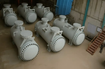
Horizontal Flash Tank
Low-headroom and high-throughput installationsCylindrical vessel on saddle supports oriented horizontally. Specified when ceiling height prevents vertical installation, or when the flash tank must handle very high condensate inlet flows that would require a vertical vessel with an impractically large diameter. Horizontal orientation increases liquid residence time for a given vessel volume, which can improve separation quality at high flow rates.
- Suitable for low-ceiling boiler houses, under-platform installations, and compact plant rooms
- Higher liquid holdup volume than a vertical vessel of the same diameter — longer residence time aids flash completion
- Inlet located mid-vessel; steam outlet at top of shell; condensate outlet at true bottom of shell
- Internal baffle between inlet and steam outlet prevents inlet turbulence from disturbing the vapour-liquid interface near the steam nozzle
- Drain must be at the geometric bottom of the shell — pipe saddle height must allow access to the drain connection
Multi-Stage Flash Tank
Cascade flash recovery, which involves several consecutive pressure reductionsA series of two or more flash vessels arranged at progressively lower pressures — each vessel receiving the liquid condensate outlet from the one above it. The condensate undergoes a further partial flash at each stage, maximising the total fraction of flash steam recovered across all stages. Used in large industrial boiler plants, power stations, and process facilities with multiple steam pressure levels.
- Stage 1 flash tank operates at the intermediate LP steam header pressure — flash steam joins the LP system directly
- Stage 2 and subsequent tanks operate at atmospheric or very low pressure — flash steam used in the deaerator or low-grade heat recovery
- Each stage recovers incrementally less flash steam, but the cumulative recovery across all stages can approach the theoretical maximum for the inlet conditions
- Economic justification requires a steam energy cost analysis — the capital cost of additional vessels must be recovered within a reasonable payback period
- Inter-stage level control is critical — liquid accumulation in an upstream tank can suppress flash and reduce recovery in the stage below
Process Flash Drum
High-pressure process applications — refineries, chemical and gas plantsA pressure vessel designed to separate vapour from liquid in a process stream — the term "flash drum" is used in refinery, petrochemical, and gas processing contexts where the vessel receives a mixed-phase stream (not condensate) and must achieve a defined vapour-liquid split for downstream process requirements. These vessels are designed to ASME Section VIII or API 520/521 depending on the application and client specification.
- Inlet distributor or impingement baffle controls inlet momentum and prevents jetting across the vapour-liquid interface
- Demister pad or mesh separator in the vapour outlet zone to achieve specified liquid carryover limits — typically <0.1 vol% liquid in vapour outlet
- Designed to process conditions: pressure up to 150 bar(g), temperature from cryogenic to 450°C depending on process
- Material of construction varies from carbon steel through 316 SS to duplex stainless and alloy steels depending on the process fluid
- Designed to API 12J, ASME Section VIII, and/or client-specified vessel standards with witness inspection at fabrication milestones
Key Components Explained
Shell (Cylindrical Body)
The main pressure-retaining cylindrical section of the vessel. Shell diameter is determined by the vapour velocity calculation — the internal cross-sectional area must be sufficient to keep upward vapour velocity below the terminal velocity of the smallest liquid droplet that must be prevented from entraining into the steam outlet. Shell wall thickness is calculated to ASME UG-27 based on design pressure, design temperature, material allowable stress, and weld efficiency.
Dished Heads
2:1 semi-ellipsoidal or standard torispherical dished heads seal the top and bottom of the cylindrical shell. ASME UG-32 governs the wall thickness calculation for each head geometry. For steam service, semi-ellipsoidal heads are preferred — they are stronger per unit weight than torispherical heads and introduce less discontinuity stress at the shell-to-head junction, which is important in cyclic pressure service such as boiler blowdown systems.
Tangential Inlet Nozzle
The condensate inlet is oriented tangentially to the vessel shell — directing the incoming condensate/flash steam mixture in a swirling path around the vessel interior wall. The centrifugal action separates heavier liquid droplets from the vapour phase before either phase reaches the vapour-liquid interface. Tangential inlets consistently outperform axial inlets in separation efficiency for the same vessel diameter, and are standard on all United Heat Exchangers flash tanks above 150 kg/hr inlet flow.
Steam (Vapour) Outlet Nozzle
Positioned at the top of the vessel, through which separated flash steam exits. Nozzle diameter is sized to maintain vapour velocity through the nozzle within a range that prevents liquid droplet re-entrainment at the nozzle entrance. A baffle or shroud is fitted around the nozzle entrance on the vessel interior to prevent direct line-of-sight between the inlet turbulence zone and the steam outlet — eliminating short-circuit carry-over.
Condensate Outlet Nozzle
Positioned at the bottom of the vessel, through which separated condensate exits under level control. A level control valve or steam trap on the condensate outlet maintains the liquid level inside the vessel — preventing steam from blowing through the condensate outlet into the condensate return line (blow-through), which would cause waterhammer and saturate the condensate return with steam bubbles.
Safety Relief Valve (SRV) Connection
Every flash tank is supplied with a flanged nozzle sized and positioned for the safety relief valve required by ASME UG-125. The SRV capacity must be sufficient to relieve the maximum possible steam generation rate under worst-case inlet conditions without allowing vessel pressure to exceed 110% of MAWP. The SRV is the last line of defence against overpressure — its sizing and the nozzle sizing calculations are part of every United Heat Exchangers flash tank design package.
Level Gauge and Instrument Connections
Sight glass level gauge connections allow visual confirmation of the operating liquid level. Additional instrument nozzles are provided for level transmitter (for control system integration), pressure gauge, and temperature element where specified. The operating liquid level is typically maintained at 30–40% of the vessel diameter — enough liquid holdup to prevent steam blow-through while not wasting separation volume above the liquid surface.
Demister Pad (Optional)
Before the flash steam leaves the vessel, entrained liquid droplets are removed using a wire mesh or structured packing demister pad installed in the vapour outlet zone. Standard mesh demisters remove droplets above 3–5 microns at design vapour velocity. Fitted as standard on process flash drums where liquid carryover limits are contractually specified, and optional on condensate flash tanks where steam outlet pipework geometry allows secondary separation downstream.
How to Size a Flash Tank: Formulas and Rules
Flash tank sizing begins with two calculations: the flash steam generation rate (which drives the vapour outlet and vessel diameter), and the condensate hold-up volume (which drives the vessel length). Both must be completed before a vessel diameter and height can be specified.
Step 1 — Calculate Flash Steam Generation Rate
The mass fraction of condensate that flashes into steam when pressure drops from P1 to P2 is given by the enthalpy balance:
Multiply x by the total condensate inlet mass flow rate (kg/hr) to obtain the flash steam generation rate. Steam tables at P1 and P2 provide the enthalpy values. For typical industrial steam systems with a 10 bar to 2 bar flash drop, x is approximately 0.12 to 0.16 — meaning 12 to 16% of the condensate mass converts to flash steam.
Step 2 — Size the Vessel Diameter
The vessel internal diameter is set by the requirement that the upward vapour velocity inside the vessel must remain below the terminal settling velocity of liquid droplets — the velocity above which droplets are carried up and entrained in the steam outlet:
The required cross-sectional area A = Qv / Vmax, where Qv is the volumetric flash steam flow rate (m³/s). Internal diameter D = √(4A/π). Round up to the next standard plate-rolled diameter.
Step 3 — Set the Vessel Length
Vessel height (for vertical tanks) must accommodate three zones: a liquid sump below the inlet with sufficient volume for 3–5 minutes of condensate holdup at the design flow rate, a separation zone between the inlet and the steam outlet providing adequate vapour disengagement height (minimum 0.6 m), and a nozzle clearance zone above the vapour-liquid interface to the steam outlet nozzle. A height-to-diameter ratio of 3:1 to 4:1 is typical for vertical condensate flash tanks.
Design Specifications and Standards
| Parameter | Standard Range | Extended / Custom Range |
|---|---|---|
| Design Code | ASME Section VIII, Division 1 | IS 2825, PED 2014/68/EU on request |
| Design Pressure | 0.5 bar(g) to 17 bar(g) | Up to 50 bar(g) for process flash drums |
| Design Temperature | −10°C to 250°C | Up to 400°C for process service |
| Internal Diameter | 200 mm to 1,200 mm | Up to 3,000 mm for large industrial installations |
| Vessel Length / Height | 500 mm to 4,000 mm | Up to 10,000 mm for multi-stage or high-throughput vessels |
| Inlet Condensate Flow | 50 kg/hr to 10,000 kg/hr | Up to 50,000 kg/hr for power station blowdown systems |
| Nozzle Rating | ASME Class 150 to Class 600 | Class 900 and above for high-pressure process drums |
| Corrosion Allowance | 1.5 mm (steam service) | 3.0–6.0 mm for aggressive condensate or blowdown chemistry |
| Weld Examination | Visual + spot RT per ASME UW-11(b) | Full RT per ASME UW-11(a) for high-pressure or cyclic service |
| Hydrostatic Test Pressure | 1.5× MAWP | Witnessed by TPI agency; test certificate included |
Material Selection Guide
Carbon Steel — SA-516 Grade 70
The standard material for boiler blowdown flash tanks and condensate flash tanks operating below 250°C with neutral to mildly alkaline condensate chemistry. SA-516-70 offers excellent weldability, high tensile strength, and low cost at the plate thicknesses used in flash tank construction. Corrosion allowance of 1.5 to 3.0 mm is included in the wall thickness calculation to account for general condensate corrosion over the design service life.
Stainless Steel — 304L / 316L
Specified when condensate chemistry is aggressive — low pH due to CO₂ absorption, chloride-containing boiler feedwater, or chemical process condensates. 316L is preferred over 304L where chloride levels exceed 50 ppm — the molybdenum addition in 316L provides superior pitting corrosion resistance in chloride-containing steam condensate. For pharmaceutical and food-grade steam applications, 316L with a 0.5 µm internal electro-polished finish is standard.
Duplex Stainless — 2205 (S31803)
Specified for high-pressure process flash drums where the service fluid contains hydrogen sulphide, chlorides at elevated temperature, or other conditions that promote stress corrosion cracking in standard austenitic stainless steels. Duplex 2205 has roughly double the yield strength of 316L — which translates to a thinner, lighter vessel wall at the same design pressure. Used in refinery, offshore, and chemical plant process flash drums.
Low-Temperature Carbon Steel — SA-333 Grade 6
Required when flash tanks operate at or below −20°C — such as cryogenic process flash drums used in LNG, air separation, and low-temperature chemical processes. SA-333-6 maintains adequate Charpy impact toughness at low temperatures where standard SA-516-70 would be brittle. Impact testing and PWHT requirements per ASME UCS-66 and UCS-68 apply to this material grade.
Industries and Applications
Flash tanks are found in any facility that generates or uses steam — which means virtually every sector of heavy and process industry. The economics of flash steam recovery are compelling wherever fuel or energy costs are significant, and the environmental case for recovering condensate (rather than discharging high-temperature blowdown to drain) is increasingly reflected in environmental permit conditions and sustainability targets.
| Industry | Flash Tank Application | Typical Pressure Drop |
|---|---|---|
| Power Generation | Boiler blowdown heat recovery; HP/LP condensate flash systems at turbine extraction points | 30–70 bar → 3–10 bar |
| Pharmaceutical | Clean steam condensate flash recovery; pure steam system blowdown; WFI (water for injection) system steam trap flash recovery | 4–7 bar → atmospheric |
| Food & Beverage | Pasteuriser and retort condensate flash; cooking vessel steam trap condensate recovery; CIP system steam condensate | 3–10 bar → 1–3 bar |
| Textile & Dyeing | Jet dyeing machine condensate flash; heat-setting stenter condensate recovery; boiler blowdown | 5–12 bar → atmospheric to 2 bar |
| Sugar & Distillery | Multiple-effect evaporator condensate flash between effects; juice heater condensate recovery; boiler blowdown | Multi-stage 10 → 5 → 2 → atmospheric |
| Chemical / Refinery | Process vessel flash drum — vapour-liquid separation; reactor effluent flash; crude distillation overhead flash drum | 50–150 bar → 5–30 bar |
How to Select the Right Flash Tank
Define the Inlet Conditions
Establish the inlet pressure (P1), inlet temperature, and maximum condensate mass flow rate. For boiler blowdown applications, use the maximum boiler operating pressure and the maximum blowdown rate as defined by the boiler manufacturer's water treatment schedule.
Set the Flash Pressure
The flash tank operating pressure (P2) is set by the destination of the flash steam — it must be slightly above the pressure of the LP steam header the flash steam will join, or atmospheric if the flash steam is used for deaeration or low-grade heating. A common design error is setting P2 too low and wasting the pressure potential of the flash steam.
Calculate Flash Steam Flow
Using the enthalpy balance formula, calculate the flash steam generation rate. This is the single most important input to vessel diameter sizing — it defines the vapour load the vessel must handle without liquid entrainment in the steam outlet.
Size the Vessel Diameter
Apply the Souders-Brown correlation to set the maximum allowable vapour velocity in the vessel, then back-calculate the minimum vessel cross-sectional area and diameter required for the flash steam flow rate calculated in Step 3.
Set Vessel Length and Nozzle Positions
Allocate the vessel length to the three required zones: liquid sump, separation zone, and vapour disengagement height. Position the inlet tangentially at mid-height; steam outlet at the top; condensate outlet at the bottom; instruments at appropriate elevations for accurate measurement.
Specify Material and Wall Thickness
Select shell and head material based on operating temperature, pressure, and condensate chemistry. Calculate the minimum required wall thickness to ASME UG-27 and UG-32, adding the specified corrosion allowance. Confirm that the selected standard plate thickness satisfies the calculated minimum.
System Benefits of a Correctly Designed Flash Tank
The value of a flash tank in a steam system extends well beyond the direct steam energy recovered. A correctly specified and installed flash tank changes the behaviour of every other component in the condensate system — improving steam trap operation, protecting condensate pumps, and reducing the load on boiler water treatment.
Energy Recovery Benchmark: A steam plant with 5,000 kg/hr of condensate returning from 10 bar HP traps to a 2 bar LP system generates approximately 700 kg/hr of flash steam — at 2 bar saturated steam enthlapy, this represents roughly 1,800 MJ/hr of recoverable heat. At a fuel cost of ₹4 per kg of steam generated, this is ₹2,800 per hour of avoidable energy cost if the flash steam is vented rather than recovered. A correctly sized flash tank with appropriate LP steam integration pays for itself in less than 6 months in this scenario.
| Benefit | Mechanism | Quantified Impact |
|---|---|---|
| Flash Steam Energy Recovery | Flash steam joins LP header — displacing LP boiler load | 10–25% reduction in LP boiler fuel consumption in high-pressure steam systems |
| Condensate Return Water Quality | Flash tank removes steam from condensate before it enters the return line — eliminating two-phase flow | Waterhammer incidents eliminated; condensate pump MTBF extended 3–5× |
| Steam Trap Performance | Removes back-pressure from trap discharge lines — traps operate at design differential pressure | Reduced steam loss from failed-open traps and a prolonged trap service life |
| Boiler Feedwater Recovery | Clean condensate returned at higher temperature — reduces makeup water requirement and boiler heating duty | Feedwater heating duty reduced by 15–30 kJ/kg of condensate returned at flash saturation temperature vs cold makeup |
| Blowdown Water Disposal | Blowdown flash tank reduces residual blowdown temperature before drain — meeting effluent discharge limits | Blowdown discharge temperature reduced from 160–180°C to 100–120°C at the flash tank outlet |
Why United Heat Exchangers
Engineering-First Design, Every Time
Every flash tank begins with a complete thermodynamic sizing calculation — flash steam generation rate, vapour velocity check, vessel diameter and height, nozzle sizing, and safety relief valve capacity — before any fabrication drawing is produced. We do not supply standard catalogue vessels for custom condensate conditions. The vessel we supply is sized for your specific inlet pressure, flash pressure, and condensate flow rate.
ASME U-Stamp Authority
The globally known ASME U-Stamp manufacturer certification, which is required for all ASME-compliant pressure vessels, is held by United Heat Exchangers. Every flash tank we manufacture is reviewed by an ASME-authorised inspector at all mandatory inspection points: material verification, fit-up, weld examination, and hydrostatic test. The Manufacturer's Data Report (MDR) documents each of these hold points and is registered with the National Board.
Steam System Integration Knowledge
A flash tank does not work in isolation. Its performance depends on the level control valve or steam trap on the condensate outlet, the sizing of the LP steam connection to the receiving header, and the back-pressure characteristics of the condensate return line. Our engineering team designs the flash tank with the surrounding system in mind — identifying potential level control problems, back-pressure issues, and steam trap selection requirements that affect flash tank performance.
Complete Documentation Package
Boiler and pressure vessel statutory compliance in India requires documented proof that every registered vessel was manufactured to a recognised design code by an accredited manufacturer. We supply the complete documentation set — MDR, MTRs, weld examination records, hydrostatic test certificate, and ASME nameplate photograph — that satisfies all statutory inspection requirements under the Factories Act and applicable state Pressure Vessels Rules.
From 50 kg/hr to 50,000 kg/hr Inlet Flow
Our flash tank manufacturing range covers vessels from 200 mm internal diameter for small industrial boiler blowdown systems to 2,400 mm internal diameter for power station condensate flash systems handling 50,000 kg/hr of high-pressure condensate. All sizes are manufactured under the same ASME quality system, the same design code authority, and the same documentation standard — regardless of vessel scale.
Replacement and Upgrade Capability
If your existing flash tank is undersized for an expanded boiler capacity, has corroded beyond its original corrosion allowance, or no longer carries valid statutory inspection certification, we manufacture a certified replacement vessel to the same or upgraded nozzle layout. Where the existing foundation and pipework geometry allow, we match the replacement vessel to minimise plant modification cost — understanding that plant shutdown time has a direct and significant economic cost.
Delivery and What's Included
What's Included with Every Flash Tank Order
- Flash tank sizing calculation sheet — flash steam generation rate (enthalpy balance), vapour velocity check (Souders-Brown), vessel diameter and height, and safety relief valve sizing — all verified against your inlet and flash pressures and condensate flow rate
- ASME U-Stamp Manufacturer's Data Report (MDR) — signed by the ASME-approved inspector; all relevant vessels are registered with the National Board.
- Material certifications (MTRs) — mill test reports for shell plate, head material, and all pressure-retaining nozzle forgings; traceable to heat and certificate number
- Weld examination records — visual examination reports and radiographic test (RT) films and interpretation records for all applicable weld categories
- Hydrostatic test certificate — vessel tested to 1.5× MAWP; test witnessed by Third Party Inspection agency; calibration certificate for test gauges included
- ASME nameplate photograph — photographic record of the stamped nameplate showing MAWP, design temperature, NB registration number, and U-Stamp impression
- Nozzle schedule and general arrangement drawing — certified dimensional drawing showing all nozzle positions, orientations, flange ratings, and vessel support details for piping design and plant layout
- Safety relief valve sizing calculation — API 520 Part I relief load calculation for the flash tank, confirming SRV orifice area requirement and recommending valve type and set pressure
- Installation and commissioning guide — support loading data, nozzle load limits, recommended piping support arrangement, level control valve type and Cv sizing guidance, and initial commissioning checklist
- Operation and maintenance manual — statutory inspection interval recommendations, level control valve maintenance schedule, internal inspection protocol, and guidance on signs of underperformance that indicate undersizing or level control malfunction
- Lifetime technical support — re-rating for changed boiler pressure or expanded condensate loads, replacement nameplate service for requalification, and performance troubleshooting throughout the vessel service life
Get a Free Flash Tank Quote in 48 Hours
Share your condensate inlet pressure, flash tank operating pressure, condensate mass flow rate, fluid type (steam condensate, boiler blowdown, or process fluid), shell material preference, and site location. Our engineering team calculates the flash steam generation rate, sizes the vessel, and delivers a complete technical and commercial proposal within 48 hours.
Request My Free Quote →Frequently Asked Questions
What is the difference between a flash tank and a separator?
The basic purpose of both a flash tank and a vapour-liquid separator is to separate a vapour phase from a liquid phase. However, the term "flash tank" specifically indicates that the vapour is produced by a pressure drop (flashing), whereas "separator" is the more general term used when the two phases arrive at the vessel already separated or partially separated. The flashing in a flash tank takes place inside the vessel, and the inflow is a single-phase liquid (condensate). A two-phase mixture is usually present at the separator's intake. The fundamentals of vessel design, such as demisters, tangential inlets, and vapour velocity sizing, are essentially the same.
How much flash steam does a boiler blowdown flash tank recover?
The amount depends on the boiler operating pressure (the inlet pressure to the flash tank) and the flash tank design pressure. For a 10 bar(g) boiler discharging blowdown to a flash tank at 0.5 bar(g), approximately 14% of the blowdown mass becomes flash steam. For a 30 bar(g) boiler, the flash fraction rises to approximately 23%. The flash steam is typically at low pressure — sufficient for deaeration heating, condensate pre-heating, or low-pressure LP steam header supply — but represents significant energy recovery relative to the alternative of discharging the entire blowdown to drain.
What causes wet steam at the flash tank outlet?
Wet steam (liquid carryover) at the steam outlet is almost always caused by one of three conditions: the vessel diameter is undersized for the actual condensate inlet flow rate, causing the vapour velocity inside the vessel to exceed the terminal settling velocity of liquid droplets; the liquid level inside the vessel is too high, reducing the vapour disengagement height above the liquid surface; or the inlet is not tangential, creating turbulence that re-entrains liquid droplets into the rising vapour stream. In an operating system, the first step is to confirm the level control valve is maintaining the correct operating level. If the level is correct and wet steam persists, vessel undersizing is the likely cause.
Does a flash tank require ASME certification in India?
For industrial applications connected to a boiler or process steam system operating above the statutory threshold pressure, ASME U-Stamp or equivalent IS 2825 certification is required under the Indian Factories Act and applicable state Pressure Vessels Rules. A flash tank directly connected to a boiler blowdown line or HP steam condensate system is a pressure vessel in boiler service — it falls within the jurisdiction of the Boiler Inspector and must be registered as a pressure vessel with the relevant state authority. Non-code vessels cannot be legally registered, cannot be insured as pressure vessels, and do not satisfy the documentation requirements of a statutory boiler inspection.
What level control arrangement is required on a flash tank?
The condensate outlet of a flash tank must have liquid level control to prevent two failure modes: If the level drops too low, steam blows through the condensate outlet into the condensate return line (blow-through), contaminating the condensate return with steam and waterhammer; if the level rises too high, liquid carryover into the steam outlet increases and the vapour disengagement zone is diminished. A pneumatic or electric level control valve on the condensate outlet, controlled by a displacer or differential pressure level transmitter, is the standard arrangement. For smaller flash tanks below 300 kg/hr inlet flow, a high-capacity float-operated steam trap on the condensate outlet can provide adequate level control without a separate control valve.
Can a flash tank recover steam from multiple steam traps simultaneously?
Yes — and this is the standard installation arrangement. A flash tank collects condensate discharge from multiple HP steam traps through a common HP condensate collection header, and the flash steam generated in the tank feeds a common LP steam header. This is more efficient than individual flash recovery from each trap, because the larger condensate flow to the flash tank justifies a properly sized vessel with good separation efficiency. The flash tank also smooths the intermittent nature of individual trap discharges — providing steady flash steam output to the LP header rather than pulsed delivery from each trap individually.
What is the delivery time for a flash tank from United Heat Exchangers?
Standard carbon steel flash tanks up to 1,000 mm internal diameter for condensate and blowdown service deliver in 3 to 5 weeks from order confirmation and approved data sheet. Stainless steel flash tanks, large-diameter vessels above 1,200 mm, and high-pressure process flash drums above 17 bar typically deliver in 6 to 10 weeks. Emergency replacement vessels for boiler house shutdowns and plant turnarounds are assessed individually — expedited manufacturing schedules are available when lead time is the critical constraint.
Author: Senthil Kumar, Technical Director — United Heat Exchangers Pvt. Ltd. | Last Updated: May 2026