Author: Senthil Kumar, Technical Director | Updated: May 2026
Table of Contents
- What Is a Fin Tube Bundle?
- How It Works
- Fin Types: G, L, LL, KL, and Extruded
- Key Components Explained
- Fin Efficiency and Why It Determines Bundle Size
- Design Specifications and Standards
- Material Selection Guide
- Industries and Applications
- How to Select a Fin Tube Bundle
- Engineering Advantages of Fin Tube Bundles
- Why United Heat Exchangers
- Delivery and What's Included
- Frequently Asked Questions
- Request a Free Quote

What Is a Fin Tube Bundle?
A fin tube bundle is the core heat transfer assembly inside an air-cooled heat exchanger. Finned tubes carry the process fluid in parallel rows held by side frames and tube sheets, while thin metal fins bonded to each tube's outer wall multiply the available air-side heat transfer area by 15 to 20 times over bare tubing — compensating for the inherently low convective coefficient of air. As a dedicated fin tube bundle manufacturer in India, United Heat Exchangers engineers and assembles complete bundles for air-cooled heat exchangers, condensers, economizers, and waste heat recovery units, thermally rated in HTRI software with a written performance guarantee on every order.
How a Fin Tube Bundle Works
The operating logic is a cascade of heat transfer resistances in series. Process fluid inside the tube gives up heat through the tube wall to the fin root, the fin conducts that heat outward toward the fin tip, and the flowing air or gas picks it up from the fin and tube outer surface. Three resistances govern the total rate: tube-side convection, tube wall conduction, and air-side convection. Fins attack the third — and largest — resistance by expanding the surface through which that air-side transfer happens.
Hot Fluid Enters Inlet Header
Process fluid — gas, steam, oil, coolant, or any process stream — enters the inlet manifold header at the bundle face and distributes across all tube circuits in the bundle. Header geometry controls velocity uniformity across the tube rows.
Flows Through Finned Tubes
Fluid travels the length of the finned tubes, transferring heat radially outward through the tube wall to the fin root. Number of tube passes and circuit arrangement control tube-side velocity, residence time, and therefore the temperature profile along the bundle depth.
Fins Conduct Heat to Surface
Each fin acts as a secondary heat transfer surface. Heat conducted from the tube wall travels along the fin toward its tip, creating a temperature gradient. Fin efficiency — the ratio of actual heat transferred to theoretical maximum — depends on fin material, height, and thickness.
Air Removes Heat Across Fins
Ambient air flows across the external fin and tube surface — driven by fans (forced or induced draft) or natural convection. The large extended surface ensures even low-velocity air removes heat at rates comparable to water-cooled bare-tube configurations in larger housings.
Cooled Fluid Exits Outlet Header
Process fluid exits at the outlet header, cooled to the design outlet temperature. Outlet temperature is a direct function of bundle size, fin density, air flow rate, and ambient temperature — all fixed parameters in the thermal design that HTRI validates before manufacture.
💡 The fin efficiency constraint: A fin does not transfer heat uniformly from root to tip. The tip is always cooler than the root — and that temperature gradient limits efficiency. Aluminum fins, with thermal conductivity around 200 W/m·K, achieve fin efficiencies above 85%. Carbon steel fins at 50 W/m·K typically reach only 65–75%. This is why aluminum fins dominate air-cooled duty even on carbon steel base tubes — the higher conductivity makes each square meter of fin surface do more thermal work for the same bundle volume.
Fin Types: G, L, LL, KL, and Extruded
The fin attachment method to the base tube governs the bundle's maximum operating temperature, resistance to thermal cycling, mechanical robustness, and unit cost. Selecting the correct fin type for service temperature and process conditions is as important as selecting the tube material.
G-Type Embedded Fins
Helical groove embedment — highest thermal and mechanical bondA continuous fin strip of aluminum or copper is wound into a shallow helical groove machined on the outer surface of the base tube. The displaced tube metal is rolled back over the fin foot, locking it permanently into the groove. The fin cannot loosen, separate, or shift under thermal cycling.
- Operating temperature up to 400°C — suitable for fired heater convection sections and economizers
- Zero contact resistance degradation under thermal cycling — fin bond strengthens over time
- Suitable for high-vibration service and outdoor installations with large seasonal temperature swings
- Higher manufacturing cost than wound fin types — justified by service life and temperature capability
- Standard specification for petrochemical plant air-cooled heat exchangers and gas turbine service
L-Type Tension-Wound Fins
L-foot tension winding — cost-effective low-temperature dutyAn aluminum or copper strip is folded into an L-profile and helically wound onto the bare tube under controlled tension. The L-foot base lies flat against the tube wall, held by tension from the winding process. No mechanical bonding into the tube surface — the fin is held by compression alone.
- Maximum operating temperature approximately 175°C — above this, differential expansion causes fin foot lift and contact resistance increase
- Lowest manufacturing cost among all fin attachment types
- Widely used for HVAC coolers, air-cooled fluid coolers, and process service below 150°C
- Foot corrosion risk in humid environments — moisture trapped under L-foot attacks the base tube surface
- Not recommended for outdoor tropical or coastal service where sustained humidity is unavoidable
LL-Type Overlapping Fins
Double foot overlap — full tube wall coverage, corrosion protectionA variant of L-fin winding where the fin foot is widened so adjacent turns overlap each other, completely covering the tube outer wall. No bare tube surface is exposed between turns — eliminating the crevice corrosion risk that limits standard L-fin in humid service.
- Full tube wall coverage between fin turns — prevents atmospheric and moisture corrosion on base tube exterior
- Slight improvement in thermal contact over single L-fin due to larger foot contact area per unit length
- Temperature limit similar to L-fin — approximately 175–200°C before differential expansion degrades contact
- Preferred over L-fin for coastal and high-humidity outdoor installations where tube corrosion is a documented site risk
- Frequently used in humid climates for general industrial cooling services and utility heat rejection coolers
KL-Type Knurled Fins
Knurled tube surface embedment — mid-temperature reliabilityThe base tube outer surface is knurled — a shallow cross-hatched pattern is machined in — before the L-foot fin is wound on. When wound, the L-foot deforms into the knurled surface, creating mechanical interlocking between fin foot and tube. The result: a stronger bond than plain L-fin without the machined groove required for G-fin.
- Operating temperature up to 250°C — significantly higher than L or LL fin due to the mechanical interlock
- Lower contact resistance than L-fin at elevated temperatures — knurling maintains bond integrity through thermal cycles
- Manufacturing cost intermediate between L-fin and G-fin — the most cost-effective option for 175–250°C service
- Widely used in refinery air coolers, power plant auxiliary cooling, and process cooling at medium process temperatures
- One of the most commonly specified fin types in new industrial air-cooled heat exchanger construction worldwide
Extruded Bimetallic Fins
Cold-formed aluminum sleeve — metallurgical bond, superior corrosion resistanceAn aluminum sleeve is drawn over the base tube and the fins are cold-formed from the sleeve wall by plastic deformation in a finning machine. The result is a seamless aluminum outer layer that is metallurgically bonded to the tube — no mechanical joint, no contact resistance, and complete galvanic separation of the tube from any atmospheric corrosion.
- No fin-to-tube contact resistance — the aluminum sleeve is the fin material, grown from a continuous outer layer
- Aluminum sleeve protects the base tube from atmospheric corrosion entirely — critical in coastal and chemical plant environments
- Operating temperature up to 300°C for aluminum; higher with copper or copper-nickel extrusion
- Best long-term performance in corrosive atmospheres where L, LL, or KL fins would fail at the foot/tube interface
- Higher capital cost — justified by the elimination of maintenance costs and extended bundle service life in harsh environments
Serrated (Slotted) Fins
Interrupted fin geometry — enhanced air-side convection coefficientSerrations — periodic notches cut into the fin edge at regular intervals — interrupt the laminar boundary layer that builds along the fin surface as air flows across it. The boundary layer resets at each notch, keeping convective transfer coefficients higher than a continuous solid fin of the same height and density.
- Air-side heat transfer coefficient 15–25% higher than equivalent solid fin at the same air velocity
- Increased pressure drop — bundle depth and fan power must account for the higher fin-side resistance
- Available in G-type, KL-type, and extruded configurations — serration is a fin edge modification, not a separate attachment type
- Preferred for compact bundle designs where a smaller face area and fewer tube rows must achieve the same thermal duty
- Not recommended for dusty or particle-laden airstreams — notches trap particulate and accelerate fouling blockage
Key Components Explained
Fin Tube Bundle Assembly Design
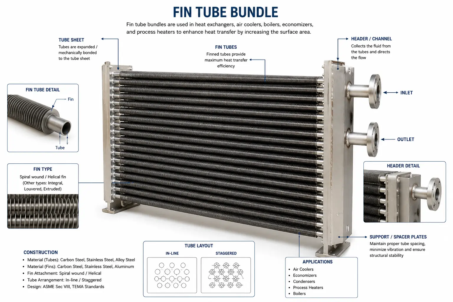
Detailed fin tube bundle heat exchanger with spiral wound finned tubes, stainless steel headers, inlet and outlet nozzles, and labeled component callouts displayed on a clean white background technical infographic.
Base Tubes
The pressure-retaining element of the bundle. Base tubes carry the process fluid at design temperature and pressure. Tube material is selected for compatibility with the process fluid and the fin material — mismatched combinations create galvanic corrosion at the fin-to-tube interface. Common tube OD range is 1 inch to 1.5 inch; wall thickness selected per API 661 or ASME requirements for the design pressure.
Fins
The extended heat transfer surface bonded to the tube exterior. The external area multiplication factor is determined by fin geometry, which includes type, height, pitch, and thickness. Fin material is chosen for conductivity (aluminum preferred for high efficiency) and corrosion resistance to the local atmospheric environment. Fin height typically ranges from 12 mm to 16 mm; fin pitch from 3 to 7 fins per 25 mm depending on the fouling service.
Tube Sheets (Headers)
Perforated plates at each end of the bundle into which the tube ends are expanded or welded. Tube sheets seal the process fluid into the tube circuit, separate the tube-side and air-side spaces, and transmit tube-side pressure to the bundle frame. Material must be compatible with the process fluid — carbon steel for clean hydrocarbon service, stainless or duplex for corrosive fluids.
Header Box
The pressure vessel chamber attached to the tube sheet through which fluid enters and exits the tube rows. Header box design — plug-type or cover-plate — determines access for tube cleaning, plugging, and inspection. Plug-type headers provide individual tube access; cover-plate headers are cheaper but require complete header removal for tube access. Design pressure rating must match or exceed the process system maximum allowable working pressure.
Side Frames and Spacer Combs
Structural members that hold all tube rows in precise alignment and at the designed transverse and longitudinal pitch. Side frames carry the weight of the tube bundle and transfer bundle weight to the supporting structure. Spacer combs — precision-slotted strips threaded between tube rows — maintain tube pitch, resist vibration-induced tube movement, and prevent adjacent tubes from contacting each other under thermal expansion.
Inlet and Outlet Nozzles
Flanged or studded connections on the header box through which process fluid enters and exits the bundle. Nozzle size and orientation follow API 661 bay layout requirements. Nozzle wall thickness and material match the header box pressure class. In multi-pass bundles, nozzle position relative to internal pass partitions determines the number of fluid passes through the tube bundle.
Pass Partitions
Internal baffle plates welded inside the header box that divide the tube rows into multiple fluid passes. A two-pass arrangement routes fluid across all rows in one direction, then reverses and traverses them again — doubling the tube-side residence time and effective tube length without increasing bundle face dimensions. More passes improve thermal effectiveness but increase tube-side pressure drop.
Vent and Drain Connections
Small-bore connections on the header box at the high and low points respectively. The vent allows air purging during liquid-phase commissioning — preventing vapor locks that reduce effective tube count and degrade thermal performance. The drain allows complete bundle evacuation for maintenance, winterization, or catalyst changeout without tube damage from retained liquid freezing.
Fin Efficiency and Why It Determines Bundle Size
Fin efficiency is a concept that directly determines how large a bundle must be to achieve a given thermal duty. Understanding it avoids the common mistake of specifying high fin density without checking whether the fin material can actually use the additional area effectively.
The fin efficiency (ηf) is the ratio of heat actually transferred by the fin to the heat the fin would transfer if its entire surface remained at the base tube temperature. For a fin of uniform cross-section, the efficiency depends on the fin height, fin thickness, fin thermal conductivity, and the air-side convective coefficient. A taller, thinner fin in a low-conductivity material — steel — will have a much lower efficiency than a shorter, thicker fin in high-conductivity aluminum.
The practical consequence: specifying carbon steel fins on a carbon steel tube bundle achieves fin efficiency of 65–75%. The same bundle geometry with aluminum fins achieves 85–92%. To meet the same heat duty with carbon steel fins, the designer must either increase bundle face area, increase tube rows, or reduce fin height — all of which add cost. In most clean-service air-cooled heat exchanger designs, aluminum fins on carbon steel tubes represent the optimal balance of fin efficiency, cost, corrosion resistance, and manufacturing simplicity.
💡 Fin density is not always more: Increasing fin density from 7 fins per 25 mm to 11 fins per 25 mm raises external surface area by approximately 30%. But it also raises air-side pressure drop by 60–80%, narrowing fin-to-fin clearance and making the bundle far more susceptible to fouling blockage. For services with dusty or particle-laden airstreams, a lower fin density of 4–6 fins per 25 mm with wider channels for particulate pass-through delivers better long-term performance than a denser core that partially blocks within the first operating season.
Design Specifications and Standards
Every fin tube bundle is custom-engineered to your process conditions, site layout, and applicable design code.
| Parameter | Typical Range / Options |
|---|---|
| Fin Type | G-type embedded, L-type tension wound, LL-type overlap wound, KL-type knurled wound, extruded bimetallic, serrated profile on all applicable types |
| Base Tube OD | 19 mm to 50 mm (¾ inch to 2 inch); 25 mm (1 inch) and 38 mm (1.5 inch) most common in industrial air-cooled service |
| Base Tube Wall Thickness | 1.6 mm to 5 mm depending on design pressure, tube material, and allowance for corrosion |
| Fin Height | 10 mm to 25 mm; 12.7 mm (½ inch) and 15.9 mm (⅝ inch) standard for industrial air-cooled heat exchangers |
| Fin Pitch (Density) | 3 to 11 fins per 25 mm; 7 fins per 25 mm standard clean service; 4–5 fins per 25 mm for fouling-prone or dusty service |
| Fin Thickness | 0.3 mm to 0.7 mm for aluminum fins; 0.5 mm to 1.2 mm for carbon steel or stainless fins |
| Bundle Face Width | 600 mm to 4,500 mm standard; wider on request for large air-cooled heat exchanger bays |
| Bundle Tube Length | 1.5 m to 12 m; 6 m and 9 m most common in API 661 standard bay designs |
| Tube Rows | 2 to 8 rows deep; 4 rows standard for most cooling duties; more rows increase thermal effectiveness but raise air-side pressure drop |
| Design Temperature | Up to 400°C tube-side (G-fin); up to 175°C (L and LL fin); up to 250°C (KL fin); up to 300°C (extruded bimetallic) |
| Design Pressure | Up to 250 bar tube-side for high-pressure gas service with appropriate tube wall thickness and header class |
| Tube Arrangement | Triangular pitch (standard — highest tube density) or square pitch (for shell-side mechanical cleaning access) |
| Number of Passes | 1-pass to 6-pass tube-side configuration; pass arrangement selected to balance tube-side velocity and pressure drop |
| Design Code | API 661 (air-cooled heat exchangers), ASME BPVC Section VIII (pressure vessels), IS 4503, TEMA C/R/B where applicable |
| Thermal Rating | HTRI Xchanger Suite — written performance guarantee issued with every bundle order |
Material Selection Guide
The correct fin and tube material combination balances thermal performance, corrosion resistance, operating temperature capability, and unit cost. No single combination suits every service — the process fluid chemistry and local atmosphere both influence the optimum choice.
Aluminum Fins / Carbon Steel Tubes
The dominant combination for industrial air-cooled heat exchangers in clean atmospheric environments. Aluminum's thermal conductivity of approximately 200 W/m·K delivers fin efficiency above 85%, minimizing bundle size. Carbon steel tubes handle process pressures up to 250 bar when wall thickness is sized accordingly. Not recommended for coastal or chemically contaminated atmospheres where aluminum fin corrosion is a documented risk.
Aluminum Fins / Stainless Steel Tubes (304/316L)
Specified when the process fluid is mildly corrosive — wet gas, condensate, amine service, or any stream that would attack carbon steel tube walls. The stainless tube resists internal corrosion; aluminum fins perform at their usual high efficiency externally. Galvanic isolation between aluminum fins and stainless tubes is maintained by the thin aluminum sleeve in extruded configurations, or by the mechanical contact resistance in wound-fin designs.
Aluminum Fins / Duplex Stainless Tubes (2205)
Used for chloride-containing process streams — brine coolers, seawater-contaminated production fluid, or process streams with aggressive halide content. Duplex stainless provides double the yield strength of 316L, allowing thinner tube walls at the same pressure rating — partially offsetting the higher material cost. The aluminum fin provides the same high air-side efficiency regardless of what duplex alloy is used for the tube.
Carbon Steel Fins / Carbon Steel Tubes
Specified for very high-temperature service — above 300°C — where aluminum fins cannot operate without losing temper and mechanical strength. Fired heater convection sections, waste heat recovery units on combustion processes, and economizers behind boilers commonly use this combination. The lower fin efficiency of carbon steel (65–75%) requires larger bundles for equivalent duty, which is accepted in exchange for the temperature capability.
Copper-Nickel (CuNi 90/10) Fins / CuNi Tubes
Specified for offshore and coastal installations where atmospheric chloride aerosols are a persistent corrosion risk to aluminum fins. Copper-nickel resists saltwater and chloride corrosion far better than aluminum, making it the standard material for air-cooled bundles on offshore production platforms, FPSOs, and marine applications where aluminum fins would corrode within a few years of service.
Stainless Steel Fins / Alloy or High-Nickel Tubes
Reserved for severely corrosive atmospheres — chemical plant environments with acid fume exposure, solvent vapor atmospheres, or any location where both the external atmosphere and the process fluid are aggressive. Stainless steel fins provide corrosion resistance on the air side; high-nickel or Hastelloy tubes protect against process-side corrosion. The highest cost combination — justified only when both attack vectors are simultaneously present.
Industries and Applications
| Application | Process Fluid / Service | Fin Type Typically Specified |
|---|---|---|
| Crude Oil Coolers — Refinery | Atmospheric crude, reduced crude, vacuum residue — process temperatures 80–250°C, high fouling potential on tube side | G-type or KL-type aluminum fins on carbon steel tubes; plug-type headers for tube-side access and cleaning |
| Overhead Condensers — Distillation | Light hydrocarbon vapors, naphtha vapors, or amine regenerator overhead — partial condensation service with varying vapor fraction | G-type embedded fins on carbon steel or stainless tubes; two-pass or multi-pass bundles for vapor-liquid flow distribution control |
| Gas Compression Aftercoolers | Compressed natural gas, nitrogen, or air after final compression stage — typically 80–150°C inlet to ambient approach | Extruded bimetallic or KL-type fins; carbon steel tubes for clean gas; stainless for wet or sour gas; aluminum fins standard |
| Lube Oil Coolers — Rotating Equipment | Turbine or compressor lube oil — 80–120°C inlet, controlling bearing temperature through oil circuit temperature management | L-type or KL-type aluminum fins on carbon steel tubes; compact two-pass bundle for space-constrained machinery house installations |
| HRSG Economizers — Power Plants | Boiler feedwater preheating using gas turbine exhaust — temperatures 200–400°C on gas side, high thermal cycling duty | G-type carbon steel or stainless fins on alloy steel tubes; in-line or staggered arrangement per exhaust duct layout |
| Ammonia and Urea Coolers — Fertilizer Plants | Liquid ammonia, process water, and nitrogen-hydrogen gas streams — corrosion risk from ammoniacal environments | G-type aluminum fins on stainless or duplex tubes; special header alloys for ammonia service compatibility |
| Offshore Production Coolers | Produced water, crude oil, wellhead gas — salt-spray-contaminated atmosphere, vibration, restricted installation footprint | Extruded or CuNi fins; stainless or duplex tubes; compact bundle configuration to fit deck space constraints |
| Dry Cooling Towers — Power Generation | Steam condensate or cooling water in large-scale air-cooled condensers and Heller-type cooling systems | G-type large-diameter aluminum fins on carbon steel oval or round tubes; high fin density for maximum duty per unit face area |
Fin Tube Bundles for Every Thermal Duty — HTRI Sized, ASME Certified
From refinery crude coolers to offshore gas aftercoolers — every fin type, every tube material, custom-engineered to your API 661 bay layout. Free technical proposal in 48 hours.
Request My Free Quote →How to Select a Fin Tube Bundle
Six engineering decisions determine the correct bundle configuration for your service. Working through them in order prevents the common mistakes of under-sizing bundles for summer peak conditions or over-specifying fin types for service temperatures that do not justify the cost premium.
What Is the Process Fluid and Its Maximum Temperature?
Process fluid temperature determines fin type directly. Below 175°C: L or LL fin is adequate and cost-effective. Between 175°C and 250°C: KL-type knurled fins maintain bond integrity. Above 250°C: G-type embedded fins are mandatory. Above 300°C with carbon steel service: carbon steel fins on carbon steel tubes, accepting lower fin efficiency in exchange for temperature capability.
What Is the Atmospheric Environment at the Installation Site?
Clean inland: aluminum fins acceptable for all fin types. Coastal or offshore with salt spray: extruded or CuNi fins. Chemical plant with corrosive fume: stainless steel fins. Wider fin pitch (4–5 fins/25 mm) to preserve cleaning access between fins if the area is dusty or particle-filled. The local atmosphere determines fin material; process fluid temperature determines fin type — both must be answered before specifying.
What Is the Required Outlet Temperature and Allowable Bundle Face Area?
Outlet temperature determines the total external surface area required. Bundle face area (width × length of tubes) and number of rows set that surface area. If face area is constrained by bay layout, more rows or higher fin density compensate — both increase air-side pressure drop and must be verified against fan motor sizing. HTRI calculates the optimum combination; there is no reliable shortcut for this calculation in industrial duty design.
What Is the Tube-Side Pressure and Fouling Characteristic?
High tube-side pressure requires heavier tube wall — which increases tube weight and cost but has no effect on fin selection. High fouling potential on the tube side requires plug-type headers for individual tube access, not cover-plate headers. On the air side, high fouling (dusty or particle-laden) requires wider fin pitch and periodic cleaning access in the structural frame design — not a thermal decision but a maintenance economics decision.
Single-Pass or Multi-Pass Bundle?
Single-pass bundles deliver maximum tube-side velocity for a given flow rate — favoring high-velocity erosion-resistant design and reducing fouling. Multi-pass increases tube-side residence time and temperature change without extending tube length — favored when bundle length is constrained but a large temperature cross is required. Passes must be selected before the thermal design is finalized, as they alter the effective mean temperature difference calculation across the bundle.
What Design Code and Inspection Standard Apply?
Petroleum refinery and gas processing service in India: API 661 governs bay layout, tube dimensions, and inspection requirements. Components that retain pressure: ASME Section VIII or a local code that is comparable for certification of pressure vessels. Export to Europe: PED compliance and EN 12952/13445 may apply. Clarifying the applicable code before detailed design avoids costly rework of tube wall calculations, header class selections, and material certification requirements that vary between standards.
Engineering Advantages of Fin Tube Bundles
The choice of air-cooled fin tube bundles over water-cooled alternatives carries engineering and economic consequences that extend well beyond the initial capital cost comparison. These advantages grow in significance over the operating life of the installation.
No Cooling Water Required
Air-cooled fin tube bundles eliminate cooling water entirely — the largest recurring variable operating cost of a water-cooled system. No cooling tower, no makeup water treatment, no blowdown disposal, and no biological fouling risk. For inland plants in water-scarce regions, eliminating the cooling water circuit is a strategic engineering decision with multi-decade water cost implications far exceeding the capital premium of a larger air-cooled bundle.
Lower Fouling Risk on the Cooling Side
Ambient air, unlike cooling water, carries no dissolved salts, biological organisms, or chemical scale-forming agents to deposit on the heat transfer surface. The air-side fouling resistance used in HTRI design is typically a fraction of the value applied to cooling water. Over the operating life of the bundle, air-side fouling remains manageable by periodic fan-side cleaning — a simpler and lower-cost maintenance task than tube-side chemical cleaning or hydro-blasting required for water-cooled systems.
Compact Thermal Intensity
Fin multiplication delivers heat transfer rates per unit of bundle volume that make very large cooling duties achievable within the standardized bay dimensions of an API 661 air-cooled heat exchanger. A single four-row bundle with G-type aluminum fins at 7 fins per 25 mm in a 6-metre tube bay achieves external surface areas of 500–700 m² — equivalent thermal area to a large shell-and-tube heat exchanger, but within a fraction of the installed footprint.
Long Service Life with Correct Material Selection
Properly specified fin tube bundles — correct fin type for the service temperature, correct fin material for the atmospheric environment, and correct tube material for the process fluid — achieve service lives of 20 to 30 years in continuous operation before bundle replacement is required. G-type embedded fins show no measurable degradation in contact resistance over decades of thermal cycling. The capital investment in correct fin type specification at procurement time pays recurring dividends across the entire installed life.
API 661 Standardization Simplifies Spares and Replacements
API 661 standardizes tube length, tube pitch, header class, nozzle placement, and bay structural dimensions across the industry. An API 661-compliant replacement bundle from United Heat Exchangers drops into an existing bay structure from any other manufacturer without modification to the supporting steelwork, piping connections, or fan ring. This standardization eliminates the qualification risk and custom engineering cost of replacement bundles ordered 15 years after the original installation.
Modular Bundle Replacement Without Plant Shutdown
In multi-bay installations, individual bundles can be replaced while adjacent bays remain in service — reducing or eliminating the need for a full plant shutdown for bundle replacement maintenance. A pre-ordered replacement bundle installed during a planned outage window of 8–12 hours, rather than a full unit shutdown of several days, represents a productivity and safety advantage that multiplies across the operating life of a large process plant.
Why United Heat Exchangers
A fin tube bundle specified with the wrong fin type for its operating temperature will develop progressively increasing fin-to-tube contact resistance as cycles accumulate. The performance degrades invisibly — no alarm fires, but the process outlet temperature creeps upward, gradually penalizing downstream operations. Getting the fin type right requires understanding the thermodynamics, not just quoting from a catalogue. United Heat Exchangers engineers every bundle from the process fluid data up.
In-House Fin Winding and Embedment
We manufacture finned tubes in-house — G-type groove embedment, KL knurling, L and LL winding, and bimetallic extrusion all produced and quality-controlled under our own roof. No reliance on outsourced finned tube supply chains that introduce dimensional variation and quality risk into the final bundle performance.
HTRI Thermal Design — Written Guarantee
Every bundle is thermally sized in HTRI Xchanger Suite at your specified process inlet and outlet conditions, ambient temperature, air flow rate, and fin geometry. We issue a written performance guarantee — the bundle delivers the outlet temperature specified in your data sheet, or we redesign at our cost.
API 661 and ASME Certification
Bundles are designed and manufactured to API 661 dimensional and structural requirements. Pressure-retaining components are ASME U-Stamp certified where applicable, with a complete Manufacturer's Data Report issued for every pressure-rated unit. Full material traceability through mill test reports on all tubes, headers, and nozzle materials.
Replacement Bundle Capability
We manufacture replacement bundles for air-cooled heat exchangers originally supplied by any manufacturer — matching existing bay dimensions, tube pitch, header class, and nozzle placement exactly. If your original manufacturer is no longer active or has extended lead times, United Heat Exchangers delivers a certified replacement bundle into your existing structure.
All Fin Types from One Supplier
G-fin, L-fin, LL-fin, KL-fin, extruded bimetallic, and serrated profiles — all supplied under one quality system and one supply contract. Mixed-service plants with varying process temperatures across different coolers receive all their bundles from a single technically accountable manufacturer.
35+ Years of Coimbatore Manufacturing
United Heat Exchangers has manufactured heat exchange equipment from Coimbatore, Tamil Nadu since the late 1980s — supplying Indian refineries, petrochemical plants, fertilizer units, and power stations. The institutional knowledge of what local process conditions and monsoon-season atmospheres demand from finned tube construction is embedded in how we specify every bundle we manufacture.
Delivery and What's Included
What's Included with Every Fin Tube Bundle Order
- Written HTRI thermal performance guarantee — outlet temperature and air-side pressure drop committed at specified process and ambient design conditions
- ASME U-Stamp documentation (where applicable) — Manufacturer's Data Report signed by the Authorized Inspector for all pressure-rated header box and tube sheet configurations
- Material certifications (MTRs) — mill test reports for all tubes, fin strip, header plates, and nozzle material; fully traceable to heat and lot number
- Hydrostatic test certificate — tube-side circuit tested to 1.5× design pressure; test witnessed and recorded in the documentation package
- Fin bond pull-out test records — sampled pull-out force testing on G-type embedded and extruded bundles to verify fin-to-tube bond integrity before dispatch
- API 661 dimensional inspection report — tube pitch, fin height, fin density, overall bundle dimensions, and header nozzle placement verified against the agreed data sheet
- Performance curves — outlet temperature and pressure drop as a function of air flow and ambient temperature across the operating range
- Installation and commissioning guide — bay sealing requirements, bundle orientation, air duct connection, first-season cleaning recommendations
- Operation and maintenance manual — periodic fin cleaning procedures, tube plugging criteria, header inspection intervals, and spare parts list with part numbers
- Lifetime technical support — thermal re-rating for changed process conditions, replacement fin strip supply, and performance troubleshooting throughout the bundle service life
Get a Free Fin Tube Bundle Quote in 48 Hours
Provide your process fluid, inlet and outlet temperatures, flow rate, design pressure, bay face dimensions, tube length, fin type preference (or let our engineers recommend), and ambient site temperature. We deliver a complete technical proposal with HTRI sizing and fin type justification within 48 hours.
Request My Free Quote →Frequently Asked Questions
What is the difference between a fin tube bundle and a bare tube bundle?
A bare tube bundle relies solely on the outer tube surface area for external heat transfer. A fin tube bundle attaches extended metal fins to the tube outer wall, multiplying the effective external area by 15 to 20 times. That multiplication compensates for the low convective heat transfer coefficient of air — making air-cooled heat exchanger bundles thermally viable for large industrial duties that would require impractically long or numerous bare tubes to achieve the same cooling effect.
Which fin type is best for high-temperature service?
G-type embedded fins are the correct choice for service above 175°C and are mandatory above 250°C. The mechanical embedment into a machined groove in the base tube prevents the fin foot from separating under differential thermal expansion — the failure mode that limits L-type and LL-type wound fins to lower-temperature service. For the specific range of 175–250°C, KL-type knurled fins offer a cost-effective intermediate option before committing to the higher manufacturing cost of full G-type embedment.
How do I know what fin density to specify?
Fin density selection balances two competing effects: more fins per unit length increases external heat transfer area but also raises air-side pressure drop and reduces the fin-to-fin clearance available for particulate to pass through without fouling blockage. For clean service with filtered or low-dust ambient air, 7 fins per 25 mm is the standard industrial specification. For dusty, desert, or coastal environments where particulate, sand, or salt crystals are present in the airstream, 4 to 5 fins per 25 mm with wider clearance between fins maintains performance across the service life without excessive maintenance cleaning frequency.
Can United Heat Exchangers manufacture a replacement bundle for an existing air-cooled heat exchanger?
Yes — replacement bundles are a significant part of our business. Provided the existing bay dimensions, tube pitch, tube length, header connection size and class, and nozzle placement are supplied or measured from the existing installation, we manufacture a certified replacement bundle that drops directly into the existing structural bay. Fin type, tube material, and fin density can be upgraded from the original specification if operating conditions or performance targets have changed since the original installation.
What maintenance does a fin tube bundle require?
Air-side fin surfaces require periodic cleaning to remove dust, pollen, insect debris, and industrial particulate that accumulates between fins and restricts airflow. Cleaning frequency depends on site environment — monthly in dusty industrial locations, quarterly in clean rural environments. Low-pressure water washing (below 7 bar to avoid fin bending) directed from the air exit side through the bundle removes most deposit types effectively. Tube-side maintenance depends on the process fluid fouling characteristics and is determined by tube inspection findings during scheduled plant turnarounds.
What is the typical service life of a fin tube bundle?
A correctly specified fin tube bundle — right fin type for temperature, right fin material for atmosphere, right tube material for process fluid — achieves a service life of 20 to 30 years in continuous industrial service before replacement is warranted. The most common causes of premature bundle replacement are incorrect initial fin type selection (leading to progressive fin contact resistance increase), atmospheric corrosion of fin material not specified for the site environment, and tube-side corrosion from a process fluid chemistry that changed after the original specification was fixed.
What are serrated fins and when should I specify them?
Serrated fins have regular notches cut into the fin edge at intervals of 3 to 6 mm along the fin height. The laminar boundary layer that develops as air moves along the fin surface is broken up by these notches, which periodically return it to a thinner, less insulating state. The result is a 15 to 25% improvement in air-side convective coefficient compared to an equivalent solid fin at the same air velocity. The tradeoff is higher air-side pressure drop and reduced tolerance for particulate fouling between the notches. Serrated fins are most cost-effective for compact bundles with face area constraints where a deeper or wider bundle is not possible and the service airstream is clean.
What is the delivery time for fin tube bundles from United Heat Exchangers?
Standard configurations — aluminum fins on carbon steel tubes in API 661 dimensions with KL or G-type fins — deliver in 6 to 10 weeks from order confirmation and approved data sheet. Stainless tube bundles, extruded bimetallic configurations, large-bay designs above 4-metre face width, or high-pressure service above 100 bar typically deliver in 10 to 18 weeks. Emergency replacement bundles for refinery turnaround outages are assessed individually — expedited schedules are available when lead time is the critical constraint.
Author: Senthil Kumar, Technical Director — United Heat Exchangers Pvt. Ltd. | Last Updated: May 2026