Author: Senthil Kumar, Technical Director | Updated: June 2026
Table of Contents
- What Is a Plate Heat Exchanger?
- How a Plate Heat Exchanger Works
- Types of Plate Heat Exchangers
- Plate Heat Exchanger Anatomy
- The Fouling and Gasket Compatibility Problem
- Engineering Advantages and Efficiency Benefits
- Design Specifications
- Material Selection
- Industries and Applications
- How to Select a Plate Heat Exchanger
- Why United Heat Exchangers
- Delivery and What's Included
- Frequently Asked Questions
What Is a Plate Heat Exchanger?
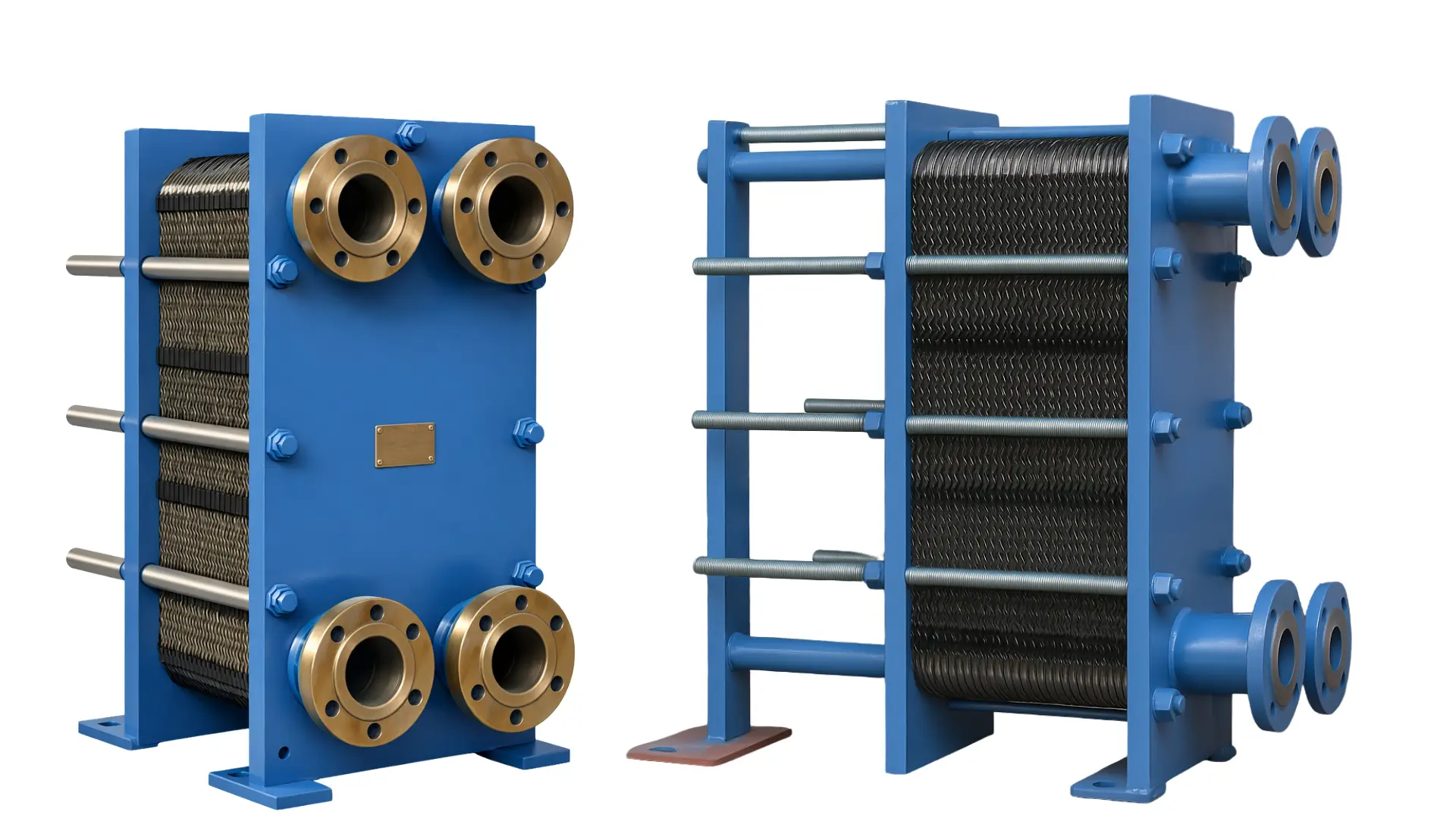
A plate heat exchanger (PHE) is an advanced thermal transfer device that uses a stack of thin, corrugated metal plates to exchange heat between two fluids without letting them mix.
Compared to traditional shell-and-tube designs, plate heat exchangers deliver 85–95% thermal efficiency while occupying roughly 20% of the floor space — making them the preferred choice wherever energy efficiency and footprint both matter.
The corrugated plate pattern forces turbulent flow at low fluid velocities, achieving heat transfer coefficients three to five times higher than smooth tube surfaces and enabling the closest temperature approaches in the industry — as tight as 1°C between the two fluid streams.
As a leading plate heat exchanger manufacturer in India, United Heat Exchangers designs and fabricates gasketed, brazed, semi-welded, and fully-welded plate heat exchangers for HVAC, food and beverage, chemical processing, refrigeration, data centre cooling, marine, and industrial process applications — in stainless steel, titanium, Hastelloy, and special alloy plate construction, with ASME Section VIII, ISO 9001, and 3-A Sanitary certification on every unit.
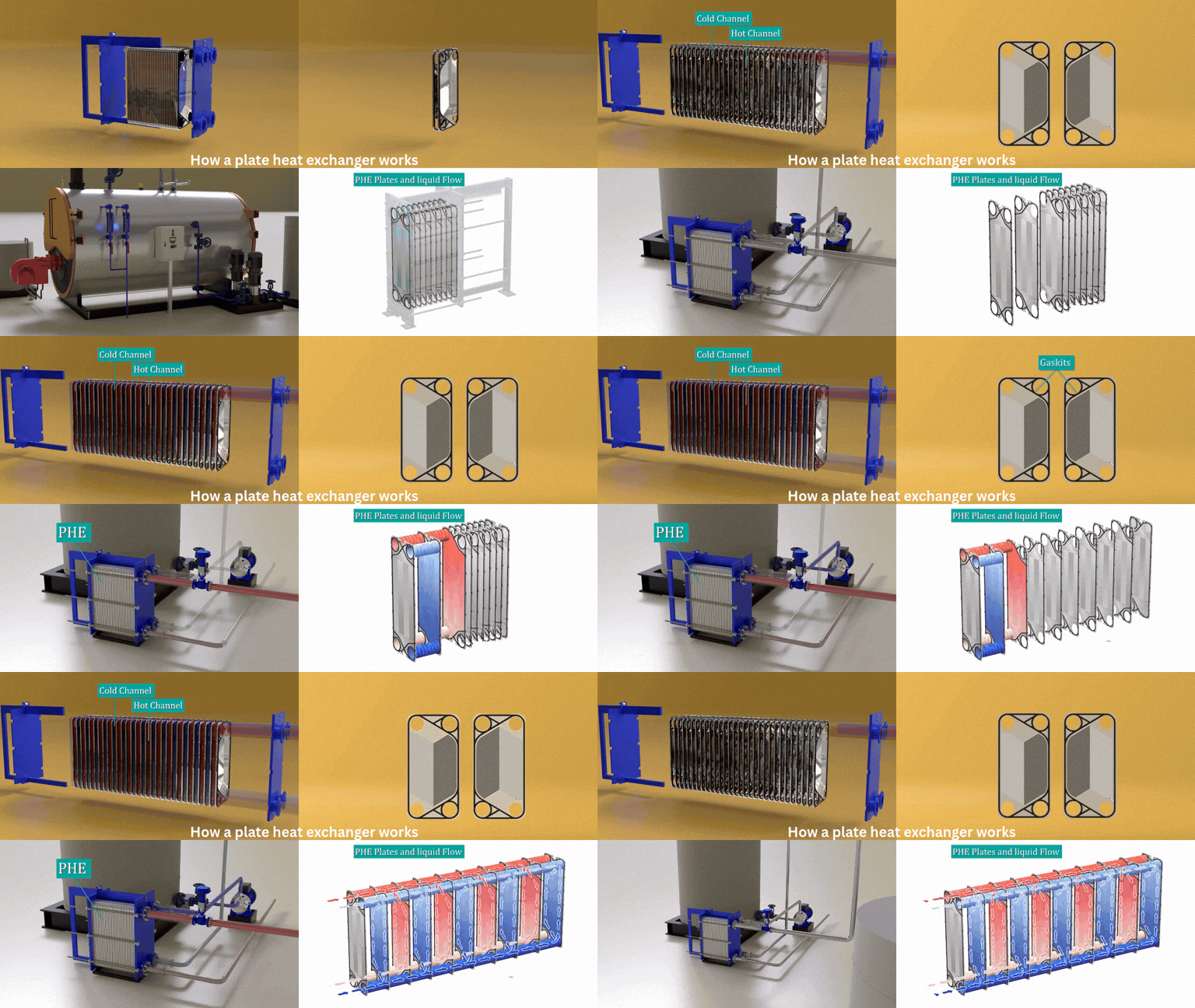
How a Plate Heat Exchanger Works
Two fluids flow through alternating channels formed between corrugated plates — hot fluid through one set of channels, cold fluid through the adjacent set, separated by a metal wall as thin as 0.4–1.0 mm. Heat conducts directly through this thin wall from the hot stream to the cold stream, and the corrugation pattern on each plate forces the flow to be turbulent at far lower velocities than a smooth tube would require.
Hot Fluid Enters
Hot fluid enters through the frame plate connection and is distributed across every alternate channel in the plate pack.
Turbulent Flow Created
Corrugations force turbulent flow (Re above 400) on both sides of every plate — increasing the heat transfer coefficient 3–5× versus a smooth surface.
Heat Conducts Through Plate
Heat passes through the 0.5 mm plate wall from the hot channel directly into the adjacent cold channel — counter-current flow maximises the temperature difference across the full plate.
Fluids Exit Conditioned
Hot fluid exits cooled and cold fluid exits preheated — both closely approaching the inlet temperature of the opposite stream, achieving the 1°C temperature approach that makes plate exchangers uniquely efficient.
Engineering Insight — Why Corrugations Matter: A flat plate would behave thermally like a smooth tube — adequate, not exceptional. The corrugated pattern does two things simultaneously: it forces turbulence at much lower flow velocities than a smooth surface would need, and it creates a self-cleaning effect that reduces fouling buildup by an estimated 40–60% compared to a flat surface, because deposits cannot settle on a constantly disturbed boundary layer. This turbulence-driven self-cleaning is the reason gasketed plate heat exchangers consistently outperform shell-and-tube designs in duties where moderate fouling is expected.
Types of Plate Heat Exchangers
Gasketed Plate Heat Exchanger (GPHE)
Elastomeric gaskets — fully disassemblable — adjustable capacityThe standard industrial plate heat exchanger configuration — the plate pack is compressed between a fixed frame plate and a movable pressure plate using tightening bolts, with elastomeric gaskets directing fluid flow and sealing each channel.
- Opens completely in 15–30 minutes for inspection, cleaning, and gasket replacement — no special tools required
- Capacity adjustable by adding or removing plates without replacing the unit
- Frame typically 10–20% oversized at manufacture to allow future expansion
- Widest choice of plate materials and gasket types for specific fluid chemistry
- Best for HVAC, food processing, district heating, general industrial cooling
- Pressure up to 25 bar; temperature up to 200°C depending on gasket type
Brazed Plate Heat Exchanger (BPHE)
Permanently brazed — no gaskets — compact and lightweightPlates are permanently brazed together with copper or nickel filler instead of gaskets — eliminating gasket maintenance entirely. BPHEs are 60–70% lighter and 75% smaller than equivalent gasketed units, and withstand significantly higher pressures.
- Copper-brazed: up to 30 bar and 200°C — standard for refrigeration and heat pump service
- Nickel-brazed: up to 45 bar and 300°C — for ammonia, steam, and high-purity applications where copper is unacceptable
- No gaskets to replace — zero gasket maintenance cost over the unit's lifetime
- Cannot be opened — CIP (clean-in-place) is the only internal cleaning method
- Best for refrigerant condensers and evaporators, domestic hot water, hydraulic oil cooling
- Cannot be expanded — a parallel unit must be added for capacity increase
Semi-Welded Plate Heat Exchanger
One welded circuit, one gasketed — aggressive fluids with maintenance accessA hybrid construction where plate pairs are laser-welded together on one fluid circuit — eliminating gasket contact with the aggressive fluid — while the other circuit retains a conventional gasket for maintenance access and inspection.
- Welded circuit: no gasket contact with the aggressive or hazardous fluid
- Gasketed circuit: standard elastomeric gasket — accessible for cleaning and inspection
- Handles ammonia refrigerant — the most common application driving semi-welded selection
- Handles concentrated acids and solvents on the welded side
- Best for ammonia refrigeration, pharmaceutical production, aggressive chemical processing
- Pressure up to 35 bar; temperature up to 250°C depending on configuration
Fully-Welded Plate Heat Exchanger
No gaskets anywhere — extreme conditions — zero fugitive emissionsPlate-and-block or plate-and-shell fully-welded construction — no gaskets anywhere in the unit. Designed for the most extreme operating conditions where no elastomeric gasket can survive and zero fugitive emission is mandatory.
- Plate-and-block: up to 100 bar and −200°C to +500°C — most extreme rating of any PHE
- Plate-and-shell: up to 42 bar and −200°C to +400°C — combines PHE compactness with shell-and-tube pressure capability
- Zero fugitive emissions — preferred for offshore, LNG, and critical power generation duties
- Cannot be field-cleaned — internal fouling requires return to factory for cleaning
- Best for offshore platforms, LNG processing, power generation, syngas cooling
- Capacities up to 50 MW in a single plate-and-shell unit
Plate Heat Exchanger Anatomy
Gasketed Plate Heat Exchanger (GPHE) — Exploded View of Key Components
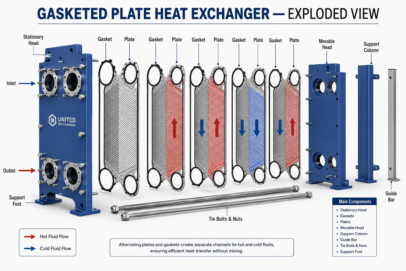
Frame Plate (Fixed Head)
The rigid steel base plate that carries all four fluid inlet and outlet connections — hot side in and out, cold side in and out — and anchors the guide and carrying bars. The frame plate is the structural backbone of the gasketed PHE; in large units it is hot-dip galvanised or epoxy coated for corrosion protection.
Plate Pack
A stack of 50–200+ thin, corrugated stainless steel (or titanium, Hastelloy) plates — 0.4–1.0 mm thick — that form the actual heat transfer surface. The corrugated pattern, either herringbone or chevron geometry, forces turbulence and creates the multiple contact points that structurally support the plate under pressure.
Gasket System
Elastomeric gaskets moulded to the periphery of each plate direct fluid into the correct channels and seal the plate pack against leakage. Gasket material — NBR, EPDM, Viton (FKM), or PTFE — is selected for the specific fluid chemistry and operating temperature on each side of the plate.
Pressure Plate (Movable Head)
The rear closing plate that slides along the guide bar under the force of the tightening bolts to compress the plate pack to its design thickness, ensuring gaskets seat correctly and all channels are sealed. Sliding the pressure plate back along the guide bar on a completely loosened PHE opens the full plate pack for inspection.
Carrying and Guide Bars
Horizontal steel bars connecting the frame plate to the support column — the carrying bar at the top supports the plate pack weight; the guide bar at the bottom keeps plates aligned. Both bars allow each plate to be individually slid out for inspection or replacement without disturbing the remaining plates.
Tightening Bolts and Nuts
Multiple stud bolts and hex nuts compress the plate pack to a defined tightened dimension — stamped on the nameplate — ensuring all gaskets are uniformly seated and the complete seal is achieved. The tightened length must always be within the specified range; over-tightening deforms plates and gaskets, under-tightening causes leakage.
The Fouling and Gasket Compatibility Problem
The most critical engineering decision in plate heat exchanger specification is matching the gasket and plate material to the actual fluid chemistry on both process sides. Specifying the wrong gasket for a process fluid is the single most common cause of premature PHE failure — and it is entirely preventable with the right up-front material selection.
Engineering Insight — Why Gasket Choice Matters More Than Plate Choice: Stainless steel and titanium plates outlast almost everything else in the heat exchanger. Gaskets are the weak point. NBR degrades rapidly above 135°C and is incompatible with steam. EPDM handles steam and hot water but attacks immediately on contact with hydrocarbon oils. Viton or PTFE are needed for aggressive chemicals — but at a meaningful cost and lead time premium over standard NBR. Specifying EPDM where the secondary fluid contains even traces of lubricant, or NBR where the fluid exceeds 120°C, leads to accelerated gasket failure, leakage, and contamination — often within months of commissioning.
| Gasket Type | Temperature Range | Chemical Compatibility | Typical Service Life |
|---|---|---|---|
| NBR (Nitrile) | −35°C to +135°C | Oils, hydrocarbons, neutral water | 3–5 years in water service |
| EPDM | −50°C to +180°C | Steam, hot water, alkaline solutions — not oils | 4–6 years in steam and hot water |
| Viton (FKM) | −20°C to +200°C | Acids, solvents, concentrated chemicals | 5–7 years in chemical service |
| PTFE | −100°C to +260°C | Aggressive acids, oxidising chemicals, near-universal resistance | 6–10 years in aggressive chemical service |
Fouling prevention by type: scale (hard water) — water softening or anti-scalant dosing; cleaned with 5% citric acid CIP every 6–12 months. Biofilm (cooling towers, open systems) — biocide treatment; cleaned quarterly with alkaline plus biocide CIP. Particulate fouling — 40–80 mesh strainers upstream; wide-gap plates (5–7 mm vs standard 3 mm) pass particles up to 5 mm and are specified for rivers, seawater, and process streams with solids content.
Engineering Advantages and Efficiency Benefits
Superior Thermal Efficiency
Corrugation-driven turbulence achieves 85–95% thermal efficiency and enables a 1°C temperature approach — performance a shell-and-tube heat exchanger of equivalent size structurally cannot match.
Compact Footprint
1–3 m² of floor space handles the same 1 MW duty that a shell-and-tube unit needs 8–15 m² to deliver — critical in retrofit installations, rooftop plant rooms, and offshore modules where every square metre is expensive.
Fast, Tool-Free Maintenance
Gasketed units open fully in 15–30 minutes for plate-by-plate visual inspection — compared to tube-pulling equipment, scaffolding, and extended downtime for a comparable shell-and-tube heat exchanger.
Modular Capacity Adjustment
Gasketed PHEs can have plates added or removed by a maintenance technician in hours, without replacing the unit — a flexibility that shell-and-tube designs cannot offer.
Self-Cleaning Flow Pattern
Turbulent corrugation-driven flow reduces fouling buildup by 40–60% versus a flat heat transfer surface, extending cleaning intervals and maintaining nearer-to-design performance for longer between maintenance interventions.
Lower Lifetime Operating Cost
Higher thermal efficiency, lower pumping power demand, and faster maintenance access reduce both energy consumption and maintenance cost throughout the plate heat exchanger's 20–30 year service life.
Design Specifications
Plate Heat Exchanger — Standard Design Parameters (United Heat Exchangers)
Material Selection
| Fluid / Service | Recommended Plate Material | Reason |
|---|---|---|
| Clean water, glycol, general industrial | SS 304 | Cost-effective; adequate corrosion resistance for low-chloride, neutral pH service |
| Process water, food, pharmaceutical | SS 316L | Superior corrosion resistance; food-safe; electropolished surface to Ra ≤ 0.4 µm for hygienic service |
| Seawater, brackish water, high chloride | Titanium Grade 2 | Outstanding chloride corrosion resistance; immune to stress corrosion cracking that excludes austenitic stainless in seawater |
| Concentrated acid, high-chloride acid | SMO 254 (6Mo stainless) | High molybdenum content; superior pitting resistance where 316L and duplex are susceptible |
| Extreme corrosion — mixed acids, chlorinated chemicals | Hastelloy C-276 | Nickel-based superalloy; broadest corrosion resistance of any standard PHE plate material |
Quality Assurance: Every plate heat exchanger we manufacture undergoes corrosion coupon testing (1,000-hour immersion in the actual process fluid), pressure cycling at 1.5× MAWP for 10,000 cycles, thermal shock testing (50 cycles), gasket chemical compatibility verification, and hydrostatic leak test before despatch. ASME-certified units receive Authorised Inspector witness on all pressure tests.
Industries and Applications
| Application | PHE Type | Why Plate Wins Here |
|---|---|---|
| HVAC and district heating / cooling | Gasketed, SS 316L or SS 304 | Close 1–3°C temperature approach reduces chiller and pump energy; fast maintenance between seasons |
| Food and beverage — pasteurisation, CIP | Gasketed, SS 316L mirror-finish | Mirror-finish plates (Ra ≤ 0.4 µm), FDA-approved gaskets, and 3-A certification; full CIP turnaround in-place |
| Ammonia refrigeration | Semi-welded, SS 316L | Welded circuit eliminates ammonia contact with gaskets; gasketed circuit allows maintenance access |
| Chemical processing | Semi-welded, titanium or Hastelloy | Wide-gap design and welded aggressive-fluid circuit; titanium or Hastelloy for acids and aggressive organics |
| Data centre free cooling | Gasketed, large frame | Lowest approach temperature maximises free-cooling hours per year, reducing chiller energy consumption |
| Marine and offshore | Gasketed or brazed, titanium | Major weight and space saving on vessels; titanium resists seawater corrosion completely |
| LNG and cryogenic | Fully-welded plate-and-block | Down to −200°C; zero fugitive emission; high surface area density for compact installation |
| Power generation — lube oil, closed cooling | Gasketed, SS 316L | Compact, high-efficiency alternative to shell-and-tube oil coolers; easy periodic cleaning |
How to Select a Plate Heat Exchanger
Define Your Requirements
Provide heat duty (kW or tons of refrigeration), hot-side and cold-side fluid type and composition, inlet and outlet temperatures, flow rates, maximum allowable pressure drop on each side, and any applicable regulatory requirement (ASME, 3-A, FDA).
Select the PHE Type
Gasketed for maintainable, adjustable-capacity general service. Brazed for compact, gasket-free refrigeration and high-pressure duties. Semi-welded for aggressive or toxic fluids on one side. Fully-welded for extreme temperatures, pressures, or zero-emission requirements.
Match Plate and Gasket Material
Select plate material for the most corrosive fluid on either side (SS 304, SS 316L, titanium, SMO 254, Hastelloy). Select gasket material for operating temperature and specific fluid chemistry — this is the most common cause of premature failure if not done correctly.
Thermal and Pressure Drop Sizing
Our engineers calculate required heat transfer area (A = Q / U × LMTD), number of plates, flow arrangement (single-pass vs multi-pass), and pressure drop on each side — targeting under 50 kPa for HVAC, under 100 kPa for industrial duty.
Frame Size and Expansion Allowance
Select a frame 10–20% larger than the current plate count to allow future capacity expansion by adding plates without replacing the unit — one of the unique economic advantages of the gasketed PHE design.
Written Performance Guarantee
Receive a written performance guarantee covering heat duty (±5%), pressure drop (±10%), minimum approach temperature, and thermal efficiency — issued with every order from United Heat Exchangers, backed by the thermal design calculation.
Why United Heat Exchangers
All PHE Types In-House
Gasketed, brazed, semi-welded, and fully-welded — sized and built in-house for your exact fluid chemistry and operating envelope, from a single manufacturer in Coimbatore.
ASME and ISO 9001 Certified
Fabrication certified to ASME BPVC Section VIII and ISO 9001:2015, with 3-A Sanitary Standards and PED 2014/68/EU compliance available for food, pharmaceutical, and European export applications.
Free Engineering Consultation
Thermal sizing, pressure drop analysis, gasket and plate material recommendation, and a written performance guarantee are all included before you commit to an order.
Written Performance Guarantee
Heat duty, pressure drop, and thermal efficiency guaranteed in writing against your design datasheet — not just a manufacturer's data sheet, but a signed performance commitment.
Replacement and Retrofit Expertise
Replacement plate packs and gasket sets matched to your existing frame dimensions, nozzle locations, and connection flanges — minimising downtime during planned maintenance shutdowns.
35+ Years Manufacturing
Decades of heat transfer equipment manufacturing from Coimbatore for Indian and export clients across the Middle East, Southeast Asia, Africa, and Europe.
Get a Free Plate Heat Exchanger Quote in 24–48 Hours
Share your fluid types, flow rates, inlet and outlet temperatures, pressure drop limits, and any regulatory requirements. Our engineers return a thermal sizing, material recommendation, gasket specification, and written performance proposal within 24–48 hours for standard applications.
Request My Free Quote →Delivery and What's Included
What's Included with Every Plate Heat Exchanger Order
- Thermal design calculation — heat duty, pressure drop, number of plates, flow arrangement, and thermal efficiency at the specified process conditions; performance guarantee in writing
- Material compatibility report — written confirmation of plate and gasket material selection for both fluid sides, including corrosion resistance assessment and regulatory compliance (ASME, 3-A, FDA, PED as applicable)
- ASME pressure test certificate — hydrostatic pressure test at 1.5× MAWP witnessed by Authorised Inspector (ASME-stamped units); test certificate issued before despatch
- Material certifications (MTRs) — traceable mill test reports for all plate material and frame structural components
- Certified general arrangement drawing — overall unit dimensions, nozzle schedule, tightened length, plate count, and installation reference marks
- Installation and maintenance guide — tightening procedure and bolt torque sequence, initial commissioning check, CIP procedure for both circuits, gasket replacement interval guidance, and troubleshooting
- Warranty — 18 months from delivery or 12 months from commissioning (whichever comes first), covering manufacturing defects, braze integrity, and structural failures under rated conditions; extended warranty up to 36 months available
Frequently Asked Questions — Plate Heat Exchangers
What is a plate heat exchanger?
A plate heat exchanger (PHE) is a heat transfer device that uses a stack of thin, corrugated metal plates to exchange heat between two fluids without mixing them. Compared to shell-and-tube designs, plate heat exchangers deliver 85–95% thermal efficiency in roughly 20% of the floor space — because the corrugated plate pattern creates turbulent flow that dramatically increases the heat transfer coefficient compared with smooth tube surfaces.
What are the types of plate heat exchangers?
The four principal types are: gasketed (GPHE) — fully disassemblable, capacity-adjustable, widest material and gasket choice; brazed (BPHE) — compact, no gaskets, copper-brazed to 30 bar or nickel-brazed to 45 bar; semi-welded — one welded circuit for aggressive fluids, one gasketed circuit for maintenance access; and fully-welded — plate-and-block to 100 bar and −200°C to +500°C, or plate-and-shell to 42 bar — for the most extreme conditions and zero-emission requirements.
What is the difference between a plate heat exchanger and a shell and tube heat exchanger?
Choose a plate heat exchanger when space is limited, energy efficiency is critical, easy maintenance access is needed, and operating conditions stay under 100 bar and 500°C — with the added benefit of a 1°C temperature approach that shell-and-tube structurally cannot match. Choose shell-and-tube when pressure exceeds 100 bar, fouling involves large particulates, or you are condensing steam with significant non-condensable content.
How often do plate heat exchanger gaskets need replacement?
NBR (nitrile) gaskets in water service: 3–5 years. EPDM in steam and hot water service: 4–6 years. Viton in chemical service: 5–7 years. PTFE in aggressive chemicals: 6–10 years. Warning signs that replacement is due include visible weep-hole drips (liquid appearing between the plates at the lower edge), a measured thermal performance drop exceeding 10%, increased pressure drop from gasket swelling, and visible external leakage at the plate pack perimeter.
Can I expand the capacity of a plate heat exchanger later?
Yes — for gasketed plate heat exchangers. Most gasketed PHE frames are manufactured 10–20% oversized, leaving room for additional plates to be inserted by a maintenance technician without any modification to the frame, pipework, or foundations. The additional plates and matching gaskets are typically available and installed in 1–2 days. Brazed and fully-welded plate heat exchangers cannot be expanded in this way — a parallel unit is added instead, which is why these systems are designed with modular expansion in mind from the initial specification.
What causes fouling in plate heat exchangers and how can it be prevented?
The three most common fouling mechanisms are: scale (calcium carbonate from hard water — prevented by water softening or anti-scalant dosing; removed by 5% citric acid CIP every 6–12 months); biofilm (cooling tower and open system bacteria — prevented by biocide treatment; removed by quarterly alkaline-plus-biocide CIP); and particulate (process streams with suspended solids — prevented by 40–80 mesh strainers upstream; wide-gap plates (5–7 mm) specified for high-solids streams). The corrugated turbulent flow in a plate heat exchanger already reduces fouling by 40–60% versus a shell-and-tube design at the same flow conditions.
Can plate heat exchangers handle condensing or evaporating applications?
Yes, with appropriate design. Condensing applications — clean steam condensers, refrigerant condensers, distillation overhead condensers — require bottom drain connections and vent ports for non-condensables. Evaporating applications — refrigerant evaporators, falling-film evaporators, and reboilers — require vapour distribution provisions and appropriate plate geometry. The key limitation is that PHEs are not well-suited for steam with more than approximately 5% non-condensable content — where the purging requirement and large vapour volume make shell-and-tube the better engineering choice.
What is the delivery time and warranty for a plate heat exchanger?
Standard gasketed and brazed plate heat exchangers ship in 4–6 weeks from order confirmation. Custom configurations, semi-welded and fully-welded units take 6–10 weeks. Spare gasket sets and replacement plates are available in 1–2 weeks. Standard warranty is 18 months from delivery or 12 months from commissioning — whichever comes first — covering manufacturing defects, braze integrity, and structural failures under rated conditions. Extended warranty up to 36 months is available.
Author: Senthil Kumar, Technical Director — United Heat Exchangers Pvt. Ltd. | Last Updated: June 2026