Author: Senthil Kumar, Technical Director | Updated: March 2026
Table of Contents
- What Is a Fixed Tube Sheet Heat Exchanger?
- How Does It Work?
- TEMA Designation Types
- Expansion Joints — When Required
- Advantages
- Limitations & Alternatives
- Fixed Tube Sheet vs. Floating Head vs. U-Tube
- Design Parameters
- Materials of Construction
- Industrial Applications
- Maintenance & Cleaning
- Standards and Codes
- Why Choose United Heat Exchangers?
- Frequently Asked Questions
What Is a Fixed Tube Sheet Heat Exchanger?
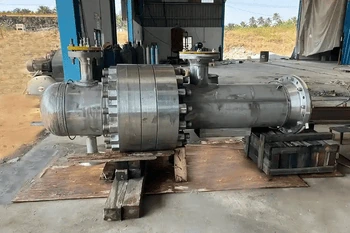
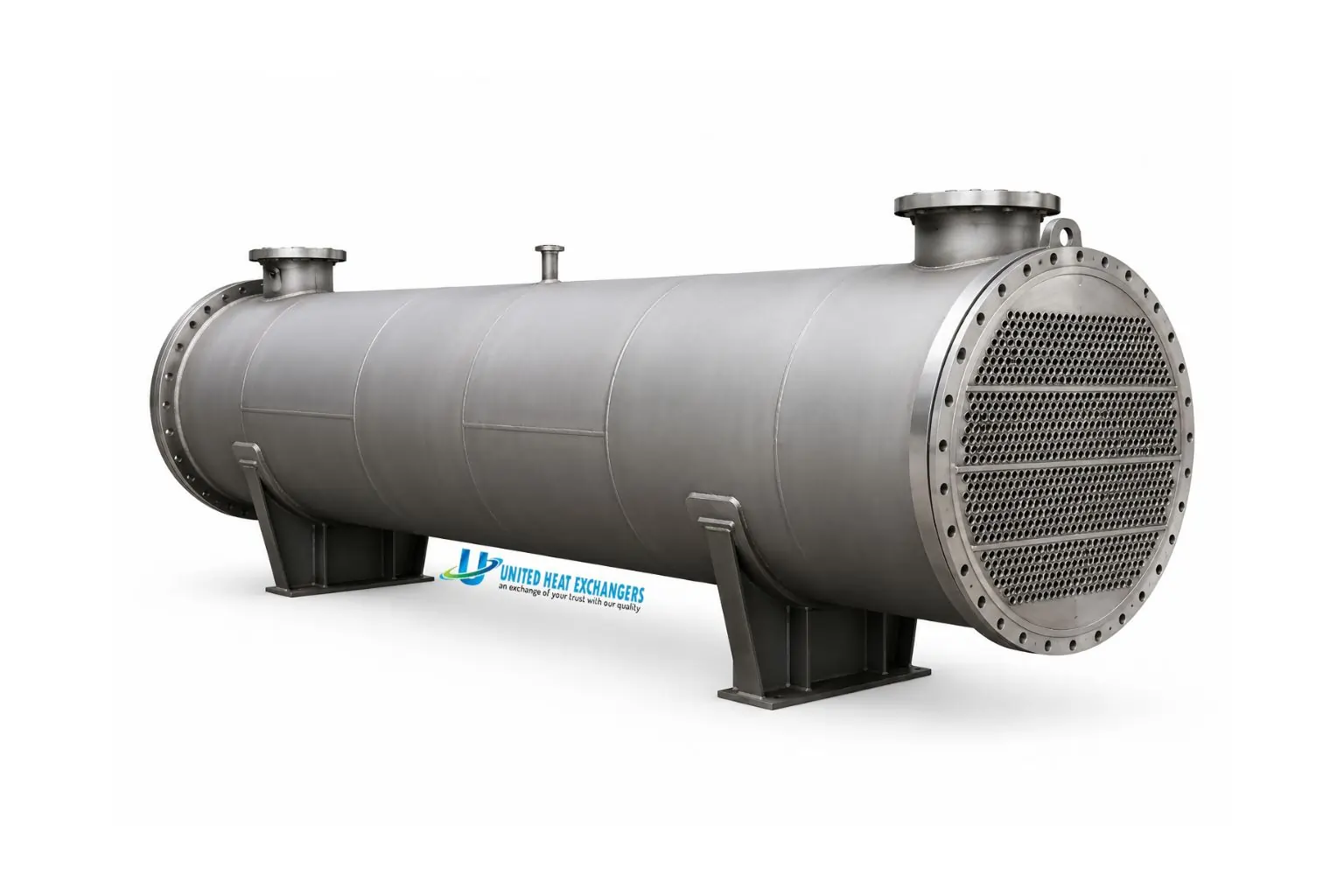
A fixed tube sheet heat exchanger is a shell-and-tube heat exchanger in which both tube sheets are permanently welded to the shell. The tube bundle cannot be removed. One fluid flows inside the tubes (tube side); the other flows over the tube bundle through the shell (shell side). The welded construction eliminates all internal seals and floating components — making this the simplest, most compact, and lowest-cost shell-and-tube configuration available.
💡 Quick definition: "Fixed tube sheet" = both tube sheets locked by direct welding to the shell. No floating internals, no internal seals, no packing glands — the fewest potential leak paths of any shell-and-tube design.
How Does a Fixed Tube Sheet Heat Exchanger Work?
Tube-Side Entry
Tube-side fluid enters through the front channel head nozzle, distributes across all tube inlets at the front tube sheet, and flows through the tube interiors.
Shell-Side Cross-Flow
Shell-side fluid enters through the shell nozzle and is directed across the tube bundle in a zigzag cross-flow pattern by segmental baffles, maximizing turbulence and heat transfer.
Heat Transfer
Heat conducts through the tube walls from the hotter fluid to the cooler. Both convective boundary layers and tube wall resistance determine the overall heat transfer coefficient.
Multi-Pass Arrangement
Pass partition plates in the channel head divide tubes into 2, 4, or 6 passes — increasing tube-side velocity, improving the heat transfer coefficient, and enabling closer temperature approaches.
Separate Exit Streams
Tube-side fluid exits through the rear channel head; shell-side fluid exits through the shell outlet nozzle. The welded tube sheets keep both circuits completely separated — no dynamic seals required.
Thermal Expansion Control
If the temperature differential between shell and tube bundle is significant, a bellows expansion joint in the shell wall absorbs differential growth and prevents dangerous thermal stress in the welded joints.
TEMA Designation Types for Fixed Tube Sheet Exchangers
TEMA uses a three-letter code: front head | shell type | rear head. For fixed tube sheet designs, the rear head is always L, M, or N. The five most specified designations are:
Bonnet — One-Pass Shell — Fixed Rear
Most economical fixed tube sheet configuration. Integral bonnet front (B) — no separate channel cover. Ideal for clean tube-side services where frequent tube-end access is not needed.
Channel with Cover — One-Pass Shell — Fixed Rear
Identical to BEM but the removable front cover (A) allows tube-end inspection and cleaning without removing the entire channel. Standard for TEMA Class R refinery fixed tube sheet service.
Fully Welded — One-Pass Shell — Fully Welded
No removable end covers — maximum leak containment. Reserved for clean services (steam, condensate, utilities) where tube-end mechanical access is never required.
Channel with Cover — One-Pass Shell — L-Type Rear
Removable front cover for tube-end access; L-type rear head mirrors the A-type front geometry. Common in chemical process and petrochemical services.
Bonnet — Two-Pass F-Shell — Fixed Rear
Longitudinal baffle in the F-type shell creates two shell passes — approximating pure counter-current flow in a single shell. Used for close temperature approach problems where two shells in series are impractical.
💡 TEMA reading guide: AEM = A (channel with removable cover) | E (one-pass shell) | M (fixed tube sheet bonnet rear). The middle letter describes the shell; the first and last letters describe tube-side access at each end.
Expansion Joints — When and Why They Are Required
Because both tube sheets are rigidly welded to the shell, differential thermal expansion between the shell wall and the tube bundle creates axial stress. If unchecked, this stress cracks the shell at the tube-sheet welds, deforms tube sheets, or loosens tube-to-tubesheet joints — all causing leakage between fluid circuits. A bellows-type expansion joint welded into the shell absorbs this differential movement without transmitting force to the tube sheets.
Per ASME Section VIII UHX, when mean metal temperature difference between shell and tube bundle exceeds ~50°F, formal thermal stress analysis is required. An expansion joint is typically mandatory above 100°F (56°C) differential in carbon steel construction.
Different coefficients of thermal expansion — e.g., carbon steel shell with stainless steel tubes — can require an expansion joint at moderate temperature differentials due to the differing growth rates of the two materials.
Plants with frequent cold starts impose cyclic fatigue on tube-sheet welds. Even if steady-state stresses are within limits, cumulative fatigue over thousands of cycles may mandate an expansion joint.
⚠ Engineer's caution: Omitting a required expansion joint is the most common — and most costly — fixed tube sheet specification error. Always run ASME Section VIII UHX differential thermal expansion analysis before finalizing any fixed tube sheet design.
Advantages of Fixed Tube Sheet Heat Exchangers
Lowest Capital Cost
No floating head parts, no internal seals, no pull-through bundle clearances — typically 15–30% less expensive than equivalent floating head designs for equal heat transfer area.
Maximum Tube Count
No floating head clearance gap needed — allows 10–20% more tubes in the same nominal shell diameter compared to a floating head unit.
No Internal Seals
Floating head designs require hard-to-inspect internal seals subject to wear and cross-contamination risk. Fixed tube sheet designs eliminate internal seals entirely.
Very High Pressure Capability
Rigid, fully welded construction handles pressures exceeding 5,000 psi on both shell and tube sides — with no dynamic seal imposing a pressure ceiling.
Compact and Lightweight
Absence of floating components, oversized shell diameters, and floating head bolting reduces overall envelope and installed weight for a given heat duty.
Easy Tube-Side Cleaning
Removable channel heads at one or both ends give direct mechanical access to all tube inlets and outlets for rodding, hydro-blasting, or brush cleaning — no bundle pull-out required.
Limitations and When to Choose an Alternative
| Limitation | Impact | When to Choose an Alternative |
|---|---|---|
| Shell side cannot be mechanically cleaned | Bundle is fixed — shell-side deposits can only be removed by chemical CIP, not mechanical lancing or hydro-blasting. | Specify a floating head (TEMA T or S) for high-fouling services: slurries, polymerizing streams, crude oil, biologically active cooling water. |
| Differential thermal expansion limits | Large shell-to-tube temperature differences create stress that can crack the shell or loosen tube-to-tubesheet joints without an expansion joint. | If ΔT > 100°F and an expansion joint is unacceptable (e.g., hazardous bellows service), choose a U-tube or floating head design. |
| Tube replacement is difficult | Failed tubes can be plugged from both ends, but full replacement requires simultaneous access to both tube sheets through the open channel ends. | For services with high tube failure probability, a floating head or U-tube design allows full bundle extraction for efficient re-tubing. |
| Expansion joint adds risk in aggressive services | Bellows is a thin-wall component vulnerable to corrosion, over-pressure, and flow-induced vibration — especially in chloride or caustic environments. | In highly corrosive services where bellows reliability is critical, a U-tube design accommodates thermal expansion through tube curvature — no bellows needed. |
Not Sure Whether a Fixed Tube Sheet Design Fits Your Application?
Our engineers review your process conditions — temperatures, pressures, fouling tendency, and thermal differential — and recommend the optimal shell-and-tube configuration with full TEMA and ASME analysis. Free consultation, no obligation.
Talk to Our Engineers →Fixed Tube Sheet vs. Floating Head vs. U-Tube
| Attribute | Fixed Tube Sheet | Floating Head | U-Tube |
|---|---|---|---|
| Bundle Removable? | No | Yes | Yes |
| Shell-Side Mechanical Cleaning | Chemical (CIP) only | Full mechanical | Full mechanical |
| Tube-Side Mechanical Cleaning | Yes — open channel ends | Yes — open channel ends | Limited — U-bend inaccessible |
| Thermal Expansion | Expansion joint when ΔT > ~50°F | Inherent — floating head moves | Inherent — U-bend flexes |
| Capital Cost | Lowest | Highest | Medium |
| Internal Seals | None | Internal floating head seal required | None |
| High-Fouling Shell Side | Not recommended | Preferred | Acceptable |
| Best For | Clean-to-moderate fouling, cost-sensitive, moderate ΔT | High fouling, large ΔT, frequent cleaning | Large ΔT, clean-to-moderate fouling, high pressure, cryogenic |
Key Design Parameters
| Parameter | Typical Range | Engineering Significance |
|---|---|---|
| Shell Diameter | 2 in – 100+ in | Sets tube count, bundle cross-section, and shell-side velocity. |
| Tube OD | ¾ in, 1 in, 1¼ in (most common) | Smaller tubes = more surface per shell volume; larger tubes resist fouling and are easier to clean. |
| Tube Pitch | Triangular (30°/60°) or square (90°) | Triangular gives ~25% more tubes; square pitch provides mechanical cleaning lanes (irrelevant for fixed tube sheet — chemical clean only). |
| Tube Passes | 1, 2, 4, 6 | More passes increase tube-side velocity and heat transfer but raise pressure drop proportionally. |
| Baffle Spacing / Cut | 20–100% of shell ID / 15–45% | Governs shell-side heat transfer coefficient and pressure drop. TEMA specifies min/max limits. |
| Design Pressure | Full vacuum to 5,000+ psi | Shell and tube sides may differ; ASME Section VIII governs minimum thicknesses. |
| Design Temperature | -320°F to 1,200°F | Sets maximum allowable stress for all materials and determines alloy requirements. |
| Fouling Resistance | 0.0001–0.003 hr·ft²·°F/BTU | Adds 15–40% extra surface area beyond clean conditions. Always design for the fouled end-of-run condition. |
Engineering tip: Design for the fouled condition at end of cleaning interval, not for startup. Adding 15–25% extra surface above the clean calculation is standard practice — far cheaper than an additional parallel shell.
Materials of Construction
| Component | Common Material | ASME Grade | Typical Service |
|---|---|---|---|
| Shell | Carbon steel | SA-516 Gr. 60/70 | General process, non-corrosive fluids |
| Shell | 316L stainless | SA-240 TP316L | Mildly corrosive process, pharmaceutical, food-grade |
| Shell | Duplex 2205 | SA-240 S31803 | Chloride-containing streams, seawater-cooled units |
| Tubes | Carbon steel seamless | SA-179 / SA-214 | Cooling water, steam, clean hydrocarbons |
| Tubes | 316L stainless | SA-213 TP316L | Corrosive process, condensate, acids, pharma |
| Tubes | Copper-nickel 90/10 | ASTM B111 C70600 | Seawater cooling, marine and offshore |
| Tubes | Titanium Grade 2 | ASTM B338 | Aggressive chloride, seawater, oxidizing acids |
| Tubes | Hastelloy C-276 | SB-622 N10276 | HCl, wet chlorine, strong oxidizing acids |
| Tube Sheets | Carbon steel + SS weld overlay | SA-516; SA-240 overlay | CS base with 3–6 mm alloy facing where tube-side is corrosive |
| Gaskets | Spiral-wound (SWG); RTJ for high pressure | ASME B16.20 | SWG standard; RTJ for >600# ASME class |
💡 Dissimilar metals: When tube and tube sheet base materials differ (e.g., SS tubes in CS tube sheet), specify a weld overlay facing on the tube sheet contact face using the same alloy as the tubes to eliminate galvanic corrosion at the tube-to-tubesheet joints.
Industrial Applications
Any service that does not require mechanical shell-side cleaning is a potential fixed tube sheet application. Their cost advantage makes them the first-choice configuration whenever process conditions permit.
| Industry | Application | Fluid Pair | TEMA Designation |
|---|---|---|---|
| Chemical Processing | Reactor feed-effluent, solvent heater/cooler, reboiler, condensate cooler | Process fluid / steam or cooling water | AEM or BEM — Class B or R |
| Oil Refining | Naphtha cooler, kerosene product cooler, amine cooler, overhead condenser | Light hydrocarbon / cooling water | AEM — Class R; API 660 |
| Power Generation | Feedwater heater, lube oil cooler, seal oil cooler, sample cooler | Steam / feedwater; oil / water | BEM or NEN — Class C or B |
| HVAC & Building Services | Chilled water exchanger, steam-to-hot-water converter, DHW heater | Chilled water / building circuit | BEM or NEN — Class C |
| Pharmaceutical | WFI cooler, pure steam condenser, synthesis heating/cooling | WFI or pure steam / cooling water | AEM — Class B; SS 316L; cGMP docs |
| Marine & Offshore | Engine jacket water cooler, lube oil cooler | Engine cooling water / seawater | AEM — Cu-Ni 90/10 or titanium tubes |
| Natural Gas Processing | Gas-gas exchanger, amine lean/rich exchanger, condensate cooler | Rich amine / lean amine; gas / gas | AEM — Class R; stainless steel |
Fixed Tube Sheet Heat Exchangers for Every Industry
From 2-inch utility coolers to 48-inch refinery exchangers — United Heat Exchangers engineers and fabricates fixed tube sheet units to ASME Section VIII, TEMA Class R/B/C, and API 660 for clients across India, the US, Middle East, and internationally.
Request My Free Quote →Maintenance and Cleaning Best Practices
Tube-Side Cleaning (Mechanical Access)
- Soft deposits: High-pressure water lance through the open channel end after unbolting the channel cover or bonnet.
- Hard scale: Mechanical tube brushing or pneumatically driven tube cleaners followed by high-pressure water flush; chemical descale if mechanical cleaning is insufficient.
- Online automated cleaning: Sponge ball systems (ATCS) continuously circulate through tubes between shutdowns — virtually eliminate tube-side fouling in cooling water service.
Shell-Side Cleaning (Chemical CIP Only)
- Circulation CIP: Circulate acid, alkaline, or enzyme-based solution through shell-side nozzles. Most practical approach for fixed tube sheet shell-side maintenance.
- Soak and drain: For light deposits — fill shell side, soak for recommended dwell time, drain, and repeat until drain runs clear.
- Always follow chemical cleaning with a thorough water rinse and corrosion inhibitor treatment where required.
Turnaround Inspection Checklist
- Eddy current or IRIS testing through open channel ends — detects wall thinning, pitting, and cracking without cutting the shell. Full-bundle survey every 3–5 years.
- Inspect tube sheet faces and tube-to-tubesheet joints for corrosion, erosion, and joint separation.
- Inspect expansion joint bellows (if present) for corrosion pitting, fatigue cracking, or mechanical damage.
- Replace all channel head, bonnet, and flanged-joint gaskets at every turnaround — never re-use compression gaskets.
- Verify pass partition plate gaskets are sealing correctly — bypass reduces tube-side velocity and heat transfer performance.
Standards and Codes
| Standard | Issuing Body | Application to Fixed Tube Sheet Units |
|---|---|---|
| ASME BPVC Section VIII Div. 1 & 2 | ASME | All pressure-containing components: shell, tube sheets, channel heads, nozzles, expansion joint. |
| ASME BPVC Appendix UHX | ASME | Fixed tube sheet thickness calculation accounting for differential thermal expansion and pressure loading — mandatory for all ASME-stamped fixed tube sheet designs. |
| TEMA Class R / B / C | TEMA | Construction tolerances, minimum baffle thickness, tie rod sizing, tube-to-tubesheet joint requirements, and fouling resistance values. |
| API 660 | API | Mandatory for most refinery and gas plant applications; adds nozzle load, vibration analysis, and enhanced inspection requirements beyond TEMA baseline. |
| EJMA Standards | EJMA | Bellows expansion joint design, cycle life rating, pressure capacity, and spring rate — applies when shell expansion joint is specified. |
| NACE MR0175 / ISO 15156 | NACE/ISO | Material qualification for sour service (H₂S) environments in oil, gas, and refinery applications. |
| PED 2014/68/EU | EU Commission | Available for European market units — CE marking with full technical file and Notified Body review. |
| IS 2825 | BIS | Indian pressure vessel standard — available for domestic Indian projects requiring statutory compliance. |
Why Choose United Heat Exchangers?
- 35+ years of manufacturing experience — fixed tube sheet units delivered to refineries, chemical plants, power stations, pharma facilities, and HVAC installations across India, the US, Middle East, Southeast Asia, and Europe.
- ASME U-Stamp and R-Stamp certified fabrication — full code documentation package with every unit.
- Full TEMA Class R, B, and C capability — construction standard matched to service severity on every order.
- API 660 licensed for petroleum, petrochemical, and natural gas applications.
- All TEMA fixed tube sheet designations: NEN, BEM, AEM, AEL, BEL, BFM, and multi-shell arrangements — engineered and fabricated in-house under one quality system.
- In-house thermal and mechanical design using HTRI Xchanger Suite, HTFS, and ASPEN EDR — complete thermal performance guarantee with every unit.
- Full ASME UHX tube sheet analysis including differential thermal expansion and expansion joint evaluation on every fixed tube sheet project.
- Complete material range: Carbon steel, 304/316L SS, duplex 2205, admiralty brass, Cu-Ni 90/10, titanium Grade 2, Alloy 825, Hastelloy C-276, and special alloys on request.
- Fast delivery: Standard designs 4–8 weeks; large or exotic alloy units 8–16 weeks.
- Free budgetary quote within 48 hours of receiving your process data sheet and project specification.
Frequently Asked Questions
1. What is a fixed tube sheet heat exchanger?
A shell-and-tube heat exchanger in which both tube sheets are permanently welded to the shell. One fluid flows inside the tubes, the other over the tube bundle. The fixed construction eliminates internal seals and floating components — making it the most cost-effective, leak-proof shell-and-tube configuration for services that do not require mechanical shell-side cleaning.
2. How does it differ from a floating head design?
In a fixed tube sheet unit, both tube sheets are welded to the shell — the bundle cannot be removed. In a floating head unit, one tube sheet is free to move axially inside the shell, accommodating large thermal expansion differentials and enabling full bundle extraction for mechanical shell-side cleaning. Fixed tube sheet: lower cost, more compact. Floating head: preferred for high-fouling services or large temperature differentials.
3. When is an expansion joint required?
When the mean metal temperature difference between shell and tube bundle exceeds ~50°F (28°C) — or when ASME Section VIII UHX stress analysis shows stress exceedance. The bellows absorbs differential thermal growth between shell and bundle, preventing weld cracking and joint failure. Omitting a required expansion joint is the most common and costly fixed tube sheet design error.
4. Can I clean the shell side mechanically?
No — the bundle is permanently fixed. Shell-side cleaning uses chemical circulation (CIP) through the shell nozzles. Tube-side cleaning is straightforward: remove the channel head cover for direct mechanical access to all tube ends.
5. What information do I need to get a quote?
Provide: fluid identification for both sides; flow rates; inlet/outlet temperatures; allowable pressure drop; design pressures; fouling tendency; special material requirements; applicable code (ASME, API 660, TEMA class); and installation orientation. Our engineers complete full thermal and mechanical design — including ASME UHX analysis and expansion joint evaluation — and deliver budgetary pricing within 48 hours.
6. Are your units ASME and TEMA certified?
Yes. All fixed tube sheet heat exchangers are designed, fabricated, inspected, and stamped per ASME BPVC Section VIII Division 1 and 2, including mandatory ASME UHX tube sheet analysis. United Heat Exchangers holds current ASME U-Stamp and R-Stamp certifications and complies with TEMA Class R/B/C, API 660, EJMA, PED 2014/68/EU, IS 2825, and NACE MR0175 as required by each project specification.
Get Your Free Fixed Tube Sheet Heat Exchanger Quote in 48 Hours
Share your process conditions — fluid data, flow rates, temperatures, pressures, fouling tendency, and applicable codes — and our thermal engineering team will size and configure the right fixed tube sheet heat exchanger for your application, backed by 35+ years of ASME-certified manufacturing experience.
Request My Free Quote →Author: Senthil Kumar, Technical Director — United Heat Exchangers Pvt. Ltd. | Published: March 2026