Table of Contents
- What Is a Shell and Tube Heat Exchanger?
- Key Components & Their Functions
- Types: Fixed Tubesheet, Floating Head & U-Tube
- TEMA Classes: R, B and C Explained
- Flow Arrangements & Pass Configurations
- Material Selection Guide
- Industrial Applications
- Design Parameters & Sizing Basics
- Shell Side vs Tube Side: Fluid Allocation Rules
- Maintenance, Cleaning & Inspection
- Troubleshooting Common Problems
- Shell & Tube vs Plate Heat Exchanger
- Frequently Asked Questions
- Get a Free Quote

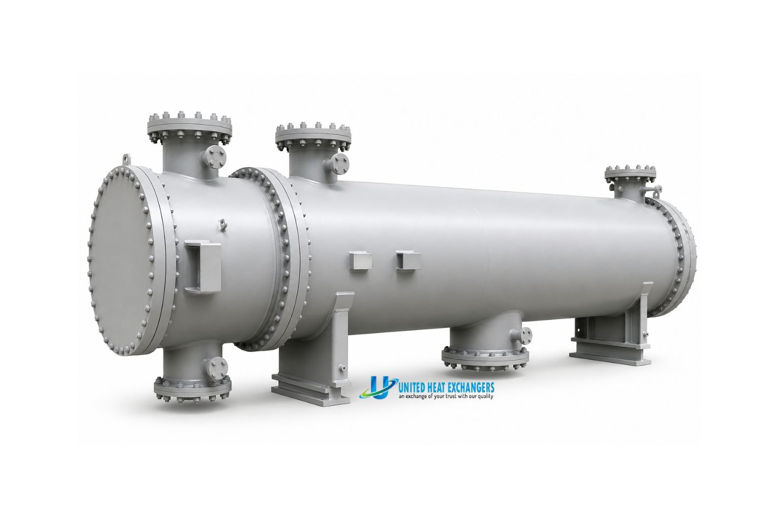
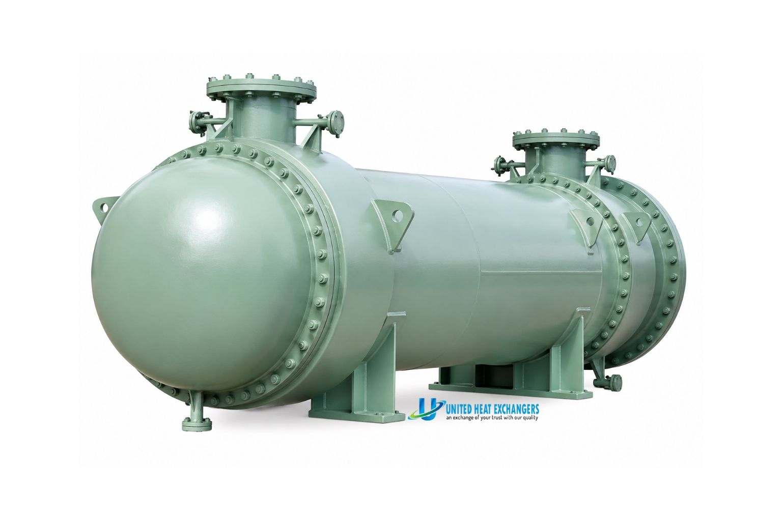
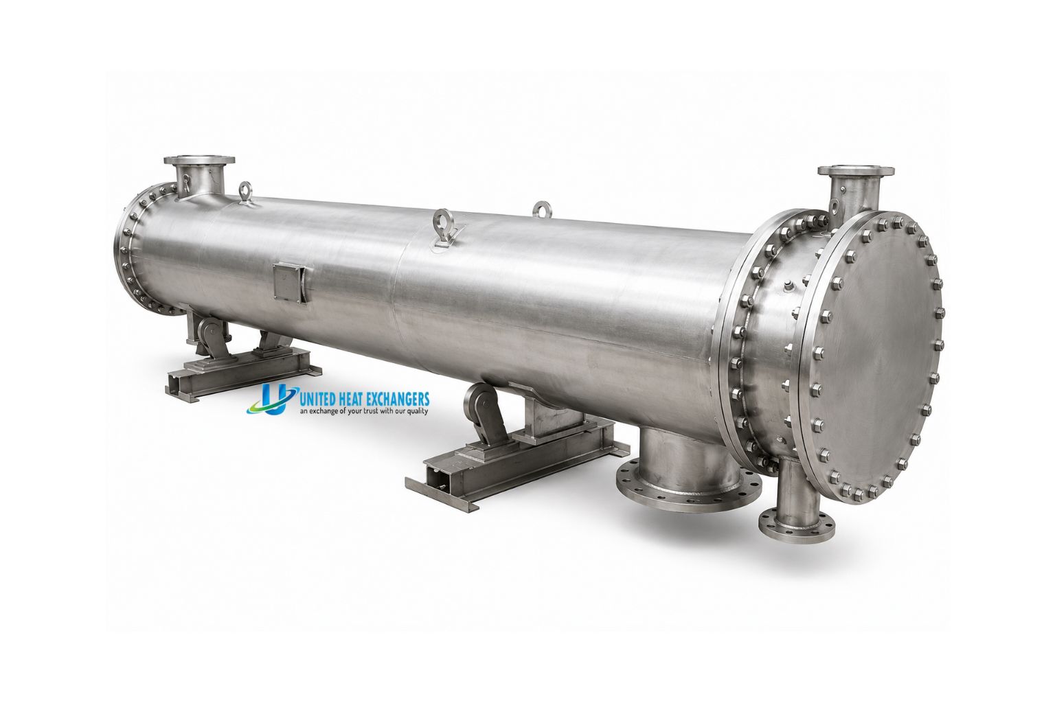
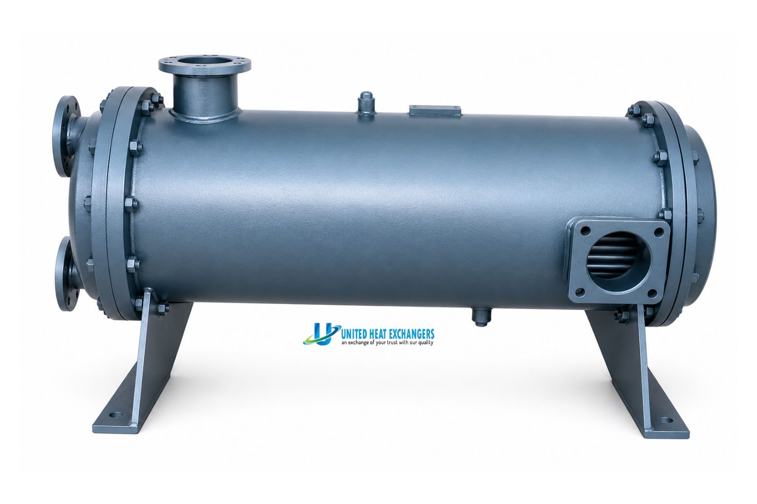
What Is a Shell and Tube Heat Exchanger?
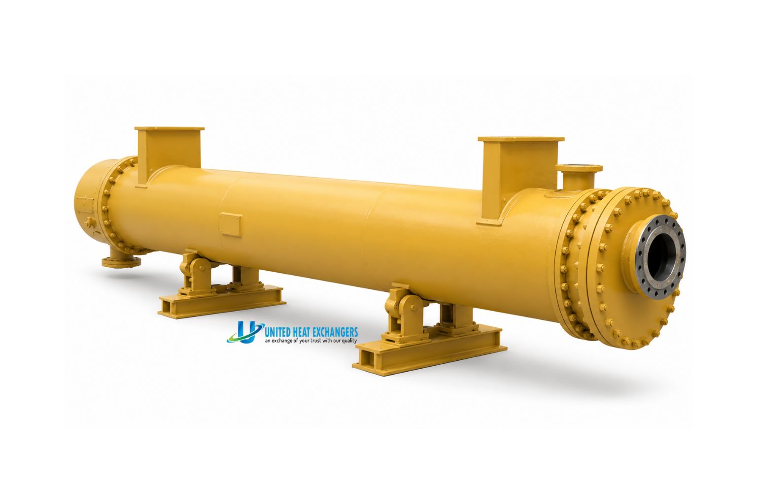
A shell and tube heat exchanger is a high-performance heat transfer system that heats, cools, condenses, or evaporates process fluids without mixing them. Built for high-pressure, high-temperature, and corrosive applications, it delivers reliable performance across oil & gas, chemical, petrochemical, power, and industrial sectors.
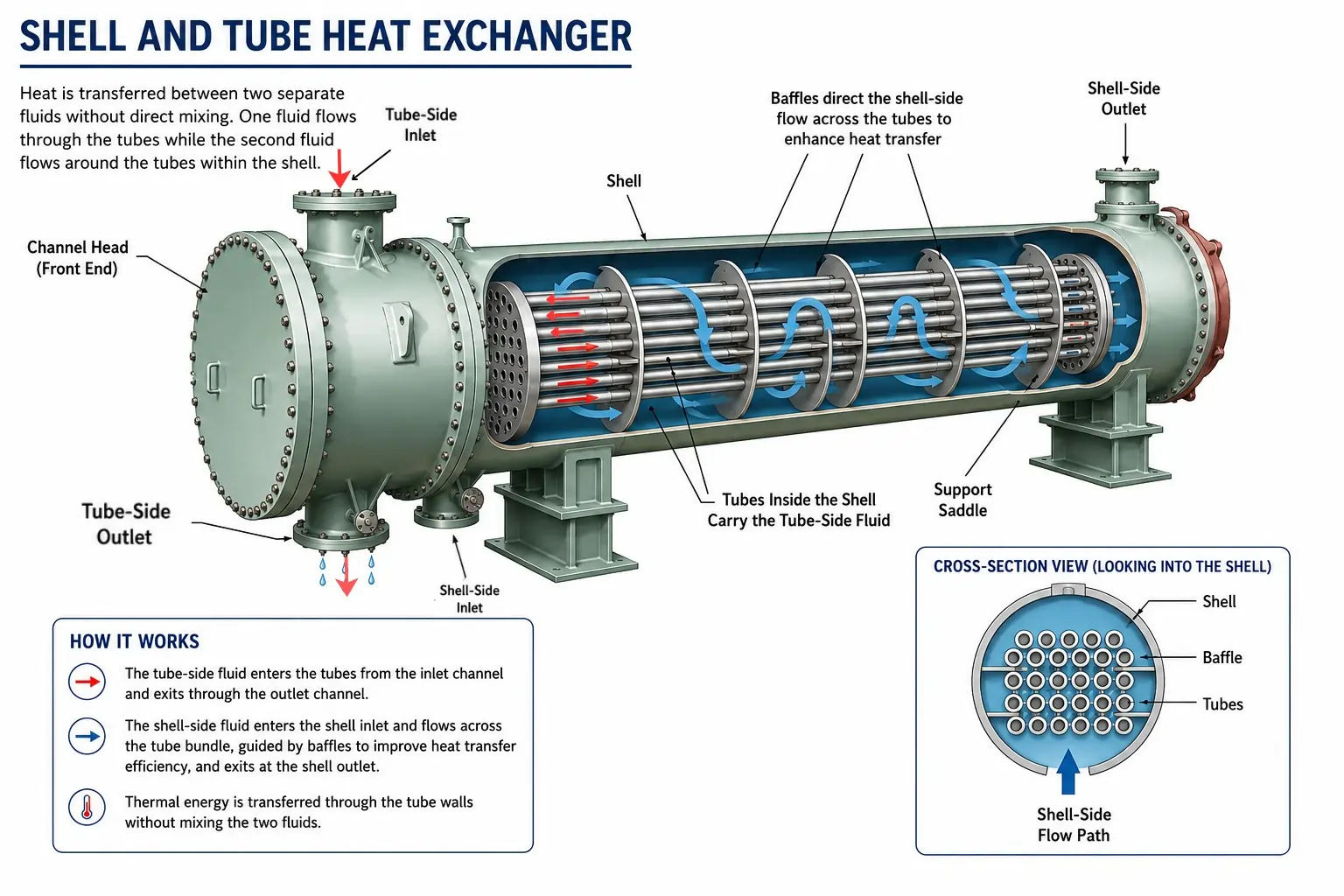
💡 Quick Definition: Think of it as dozens (or hundreds) of small pipes bundled tightly inside one large pipe. Hot fluid runs through the small inner pipes. Cold fluid wraps around them inside the outer shell. Heat crosses the pipe walls — and thermal energy is transferred with precision, reliability, and safety.
Key Components & Their Functions
Understanding each component helps you specify, operate, and troubleshoot a shell-and-tube heat exchanger correctly. Every part plays a critical role in safety, performance, and service life.

The cylindrical outer pressure vessel containing the tube bundle. Made from carbon steel, stainless steel, or alloy plate. Carries the shellside fluid and forms the pressure boundary on that side.
The heart of the exchanger — an array of parallel tubes through which the tubeside fluid flows. Bundle diameter, tube count, length, pitch, and layout pattern all control thermal performance.
Thick metal plates at each end of the shell into which all tubes are expanded or welded. They seal the tubeside fluid from the shellside fluid — the most critical joint in the exchanger.
Segmental or helical plates inside the shell that force shellside fluid to flow across the tube bundle rather than parallel to it. This dramatically increases turbulence and heat transfer coefficient.
End compartments at each end of the exchanger that distribute tubeside fluid into (and collect it from) the tubes. The channel cover is removable for tube inspection and cleaning.
Flanged pipe connections on the shell and channels for fluid inlet and outlet. Properly sized nozzles prevent erosion, vibration, and excessive pressure drop at the entry point.
Metal rods that hold the baffles at the correct spacing along the length of the tube bundle. Correct spacing is essential for preventing tube vibration — a major cause of fatigue failure.
A flexible bellows section on the shell of fixed-tubesheet exchangers. Absorbs differential thermal expansion between the tubes and the shell — eliminating dangerous thermal stress in high ΔT services.
Types of Shell and Tube Heat Exchangers
There are several distinct shell and tube heat exchanger types, each suited to different process conditions. Selecting the right type is not optional — the wrong choice creates maintenance problems, reduced efficiency, or outright mechanical failure. Here is a clear summary of the main types in industrial use, along with design notes for each.
1. Fixed Tube Sheet
Both tube sheets are fixed to the shell. No floating elements. The simplest and lowest-cost construction.
- Best for: Low differential temperatures, clean fluids, cost-sensitive applications.
- Limitation: Tube bundle cannot be removed; shell-side can only be chemically cleaned.
2. U-Tube
Tubes are bent into U-shapes. One free tube sheet. Bundle is removable for inspection and maintenance.
- Best for: High temperature differentials, high-pressure hydrogen service, steam heaters, and applications requiring full bundle removal for cleaning.
- Limitation: Inner U-bend tubes cannot be mechanically cleaned — tube-side must be a clean, non-fouling fluid.
3. Floating Head
One tube sheet is free to move inside the shell.
- Best for: High temperature differentials with fouling fluids. Allows full mechanical cleaning of both sides.
- Best for: preferred type in refineries and petrochemical plants where process fluids foul heavily and high temperature swings are common.
4. Kettle Reboiler
Oversized shell with a weir. Allows vapour-liquid separation inside the unit.
- Best for: Distillation column reboiling duty. Common in refineries and chemical plants.
5. Double Pipe
Single tube inside a larger outer pipe. Simplest form of the shell-and-tube concept.
- Best for: Small duties, pilot plants, research, or when process contamination risk is very high.
6. Multi-Pass
Tube-side fluid makes two or more passes through the shell.
- Best for: When higher thermal performance is needed without increasing shell length or when dealing with a low flow rate on the tube side.
| Type | Key Feature | Best For | TEMA Standard |
|---|---|---|---|
| Fixed Tube Sheet | Both tube sheets welded to shell | Low ΔT, clean fluids, cost-sensitive | TEMA B, C, R |
| U-Tube | Tubes bent into U-shape, single tube sheet | High ΔT, high pressure, clean tube-side | TEMA B, R |
| Floating Head | One tube sheet floats inside shell | High ΔT, fouling fluids, refinery/chemical | TEMA R |
| Kettle Reboiler | Oversized shell with vapour disengagement | Distillation reboiling | TEMA R, B |
| Double Pipe | Single tube inside a pipe | Small duties, pilot plant | TEMA C |
| Multi-Pass | 2, 4, or 6 tube passes | High thermal duty, limited shell length | TEMA B, C, R |
At United Heat Exchangers, we manufacture all of these types. We also design to TEMA standards — TEMA-R for the most demanding refinery and petrochemical service, TEMA-C for general industrial, and TEMA-B for chemical process industries. Every unit is built to the specification the application demands.
TEMA Classes: R, B and C Explained
The Tubular Exchanger Manufacturers Association (TEMA) sets the global mechanical design standard for shell-and-tube heat exchangers. TEMA defines minimum thicknesses, fabrication tolerances, impingement protection, bypass sealing, and materials requirements. Understanding TEMA classes ensures you specify the right level of construction for your service.
| Criterion | TEMA Class R | TEMA Class B | TEMA Class C |
|---|---|---|---|
| Intended service | Severe petroleum refinery & related processing | Chemical process service | General commercial & process applications |
| Construction standard | Heaviest — maximum safety margins | Intermediate | Lighter — cost-optimised |
| Corrosion allowance (min) | 3.2 mm (0.125") | 1.6 mm (0.0625") | 0.75 mm (0.030") |
| Tube-to-tubesheet joint | Expanded + seal welded | Expanded or welded | Expanded |
| Bundle bypass sealing | Sealing strips & dummy tubes required | Sealing strips recommended | Not specified |
| Impingement protection | Required unless velocity criteria met | Required unless velocity criteria met | Not mandatory |
| Typical industries | Oil & gas, refining, petrochemical | Chemicals, polymers, pharmaceuticals | HVAC, general utilities, food processing |
✅ Which TEMA class do you need? If your process involves petroleum service, toxic fluids, or high-temperature/pressure conditions — specify TEMA Class R. For standard chemical processing, Class B is the industry norm. Class C is appropriate for clean, low-risk, low-pressure utility applications only.
Flow Arrangements & Pass Configurations

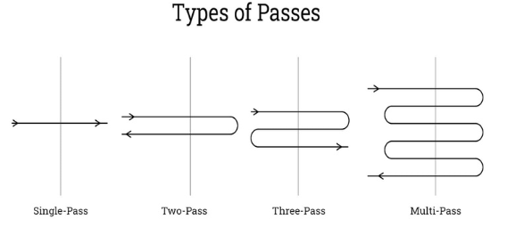
The number of passes on each side controls the temperature approach achievable, pressure drop, and thermal efficiency. Getting this right at the design stage prevents costly retrofits later.
| Configuration | TEMA Shell Type | Description | Best Used When |
|---|---|---|---|
| 1-2 (1 shell pass, 2 tube passes) | E shell | Most common. Fluid enters one channel, crosses the full tube length twice, exits the same end. | Standard heating/cooling duties. Most general-purpose services. |
| 1-4 / 1-6 (multi-pass tube) | E shell | Tube fluid makes 4 or 6 passes. Increases residence time and heat transfer for low flow rates. | Viscous tubeside fluid or low tubeside flow rate needing higher velocity. |
| 2-4 (2 shell passes, 4 tube passes) | F shell (longitudinal baffle) | Shell fluid makes two passes. Approaches true counterflow performance. | Close temperature approaches (<5°C) or crossing temperatures. |
| Series shells | Multiple E shells | Two or more shells in series to achieve temperature profile impossible in a single shell. | Very large heat duties, temperature cross situations, phased capacity expansion. |
| J shell (divided flow) | J shell | Shell fluid enters centrally, splits and exits at both ends. Halves shellside pressure drop. | Low-pressure vapour condensing or shellside pressure drop is the limiting constraint. |
| X shell (cross flow) | X shell | Shell fluid flows perpendicular to tubes — minimum shellside pressure drop. | Condensing service with near-zero allowable shellside pressure drop. |
Not Sure Which Shell & Tube Design Is Right for You?
Our ASME/TEMA-certified engineers will analyse your process data and recommend the optimal type, TEMA class, pass configuration, and material — free of charge.
Get Free Engineering Advice →Material Selection Guide for Shell and Tube Heat Exchangers
Material selection determines corrosion resistance, pressure rating, temperature capability, service life, and cost. There is no universal "best" material — the right choice matches your specific fluid chemistry and operating conditions.
| Material | Max Temp | Key Strength | Avoid With | Typical Application |
|---|---|---|---|---|
| Carbon Steel (A106, A516) | 425°C | Low cost, wide availability, good strength | Wet CO₂, H₂S, acids, seawater | General process, steam, non-corrosive oils |
| Stainless Steel 304 | 870°C | Good corrosion resistance, food-safe | High chloride concentrations (>200 ppm at temperature) | Food, beverage, mild chemical service |
| Stainless Steel 316L | 870°C | Enhanced chloride resistance, low carbon for welding | Hot concentrated chlorides, H₂SO₄ >50% | Pharma, marine, general corrosive service |
| Duplex SS 2205 | 315°C | 2× strength of 316L + superior pitting resistance | Temperatures above 315°C (embrittlement risk) | Seawater, bleach, offshore, desalination |
| Titanium Grade 2 | 300°C | Outstanding seawater & chloride corrosion resistance | Fluoride-containing fluids, red fuming nitric acid | Seawater coolers, chlorine, bleach, marine |
| Copper-Nickel 90/10 | 300°C | Excellent seawater resistance, anti-biofouling | Ammonia, oxidising acids, high-velocity seawater | Marine, coastal power plants, desalination |
| Inconel 625 | 980°C | High-temperature oxidation resistance, excellent fatigue strength | Very few limitations — a highly versatile alloy | Gas turbine exhausts, flue gas, high-temp chemical |
| Hastelloy C-276 | 650°C | Industry standard for HCl, wet chlorine, mixed acids | Strong oxidising agents at high temperature | Acid services, chlorine processing, flue gas desulphurisation |
| Chrome-Moly (P11, P22, P91) | 650°C | High-temperature creep strength, steam oxidation resistance | Wet H₂S (PWHT required), aqueous corrosion | High-pressure steam, power plant feedwater heaters |
⚠ Critical rule: Never select carbon steel for seawater, chloride-rich cooling water above 60°C, or any wet hydrogen sulphide (sour gas) service without full compliance with NACE MR0175 / ISO 15156. Wrong material selection is the number-one cause of premature heat exchanger failure.
Industrial Applications of Shell and Tube Heat Exchangers
Shell-and-tube heat exchangers are found in every major industrial sector. Below are the most critical applications and what makes each one unique.
 Oil & Gas and Petroleum Refining
Refineries are the heartland of shell-and-tube technology. A single crude distillation unit may contain over 100 shell-and-tube exchangers performing different duties simultaneously. Key services include:
- Crude oil preheat trains: Series of exchangers heating cold crude feed using hot product streams before the atmospheric distillation column. Recovers 15–25% of fired heater fuel cost.
- Overhead condensers: Condense vapours leaving the top of distillation columns using air or water — horizontal shellside condensing design.
- Reboilers: Vaporise bottom liquid using steam or hot oil. Vertical thermosiphon is the most common refinery design.
- Reactor feed-effluent exchangers (RFEE): Preheat cold reactor feed using hot reactor effluent — critical for controlling exothermic reaction and minimising fired heater load.
- Compressor coolers / intercoolers: Cool compressed gas between stages, removing condensate and improving compression efficiency.
 Power Generation
- Main steam condensers: Some of the world's largest shell-and-tube units — up to 10,000 m² surface area — convert turbine exhaust steam back to condensate, maintaining vacuum and maximising power output. Titanium tubes for seawater-cooled coastal plants.
- Feedwater heaters (closed type): Preheat boiler feedwater using extracted turbine steam, improving overall thermal efficiency by 5–8 percentage points.
- Lube oil coolers: Maintain turbine and generator bearing lubricant at 40–55°C operating temperature for reliable operation.
 Chemical & Petrochemical Processing
- Reactor coolers / trim coolers: Precise temperature control of exothermic reactions. Often TEMA Class R with high-alloy tubes for corrosive process streams.
- Distillation column condensers and reboilers: Every distillation column in a chemical plant requires at least one condenser at the top and one reboiler at the bottom — both are typically shell-and-tube designs.
- Polymer plant heat exchangers: Heated jackets and tube bundles control viscous polymer melt temperatures in reactors and pipeline sections.
 Food, Beverage & Pharmaceutical
- Double-tubesheet designs prevent any possibility of cross-contamination between process fluid and heating/cooling medium — mandatory for WFI (water for injection) in pharma.
- Electropolished 316L stainless steel tubes and sanitary surface finishes comply with FDA and GMP requirements.
- Used for product pasteurisation, CIP cleaning fluid heating, and sterile condensate generation.
 Marine & Offshore
- Titanium or copper-nickel tubes resist seawater corrosion — a major failure mode for lesser materials.
- Designed to classification society standards (ABS, DNV-GL, Lloyd's Register) for vessel certification.
- Applications: engine jacket water cooling, lubricating oil cooling, fuel oil heating, HVAC seawater-cooled condensers.
 HVAC & Building Services
- Large central chiller evaporators and condensers in commercial buildings use shell-and-tube construction for reliability and longevity.
- District heating primary-to-secondary heat transfer stations handling pressures and temperatures beyond the capability of plate exchangers.
- Swimming pool and spa heating systems where reliability and 20+ year service life are required.
Design Parameters & Sizing Basics
Proper sizing requires accurate process data. Undersized exchangers fail to meet temperature targets; oversized units waste capital and can cause operational problems including vibration and maldistribution. Here are the critical parameters:
| Parameter | Units | Why It Matters |
|---|---|---|
| Fluid types (hot & cold) | — | Determines material selection, fouling factor, and TEMA class |
| Flow rates | kg/hr or m³/hr | Controls heat duty, velocity, and pressure drop calculations |
| Inlet & outlet temperatures | °C or °F | Determines LMTD (Log Mean Temperature Difference) — the thermal driving force |
| Operating pressures | bar or psi | Sets shell and tube wall thickness, ASME class, and flange rating |
| Allowable pressure drop | kPa or psi | Constrains tube velocity, baffle spacing, and number of passes |
| Fluid viscosity, density, Cp, thermal conductivity | Various | Required to calculate Reynolds number, Prandtl number, and heat transfer coefficients |
| Fouling resistance (Rf) | m²·K/W | TEMA provides standard values — directly impacts required heat transfer area (adds 15–40% to clean area) |
| Design margin | % | Typically 10–15% added to calculated duty — protects against future process changes and fouling accumulation |
📌 The basic heat exchanger equation:Q = U × A × LMTD × F where Q = heat duty (W), U = overall heat transfer coefficient (W/m²·K), A = heat transfer area (m²), LMTD = log mean temperature difference (°C), F = correction factor for pass configuration. All design calculations flow from this equation.
Shell Side vs Tube Side: Fluid Allocation Rules
Deciding which fluid goes on the tube side and which goes on the shell side is one of the most important — and most frequently misunderstood — decisions in heat exchanger specification. Follow these engineering rules:
Place on the Tube Side:
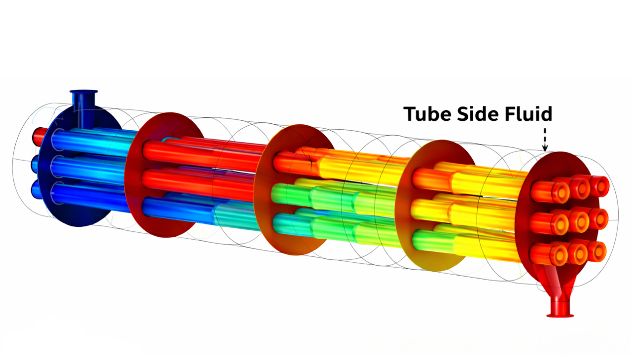
- Corrosive or aggressive fluids — The tube side is easier to fabricate from expensive corrosion-resistant alloys (only tubes and two tubesheets need to be alloy; the shell can remain carbon steel).
- High-pressure fluids — Tubes are inherently high-pressure-rated; a high-pressure shell is far more expensive. Tube side is far cheaper to design for 5,000+ psi.
- Hazardous or toxic fluids — The tube side is a more contained, easier-to-seal system. Leaks are also easier to detect at the channel end.
- Fluids requiring high velocity — Multiple tube passes raise tubeside velocity easily, increasing the heat transfer coefficient and reducing fouling.
- Sterile or pure fluids (pharma) — Double-tubesheet designs use the tube side for the pure/sterile fluid to prevent cross-contamination risk.
Place on the Shell Side:

- Viscous fluids — Shellside flow with baffles creates turbulence even at low velocities, maintaining an adequate heat transfer coefficient for fluids that would be laminar in tubes.
- Condensing vapours — Horizontal shellside condensing on the outside of tubes is the standard industrial configuration, with condensate draining by gravity to the bottom.
- Fluids with low pressure drop allowance — The shell side inherently has lower pressure drop than the tube side for equivalent flow, particularly with J or X shell configurations.
- Fluids requiring temperature profile control — Multiple shell passes or interconnected multi-shell arrangements can achieve precise temperature profiles on the shell side.
 Maintenance, Cleaning & Inspection
A structured maintenance programme is the single most cost-effective investment in a shell-and-tube heat exchanger's life. Operators who clean and inspect proactively spend 60–70% less on repairs than those who wait for failures.
📅 Routine Operational Monitoring (Weekly)
- Record inlet/outlet temperatures on both sides — compare with commissioning baseline values
- Calculate and log the Overall Heat Transfer Coefficient (U-value) — trending downward means fouling is building up
- Monitor pressure drop across shell side and tube side — a rising ΔP is the earliest measurable sign of fouling
- Check for any external fluid leaks at flanges, nozzles, channel covers, and drain connections
- Listen and check for unusual vibration or noise — early signs of tube bundle resonance
📅 Scheduled Shutdown Inspection (Annual or Per Turnaround)
- Remove channel cover and visually inspect all tube ends for corrosion, erosion, pitting, or blockage
- Pull bundle (floating head and U-tube types) for full external visual and NDE inspection
- Perform eddy current testing (ECT) on all tubes — detects wall thinning, pitting, and cracking non-destructively
- Mechanically brush or high-pressure lance all accessible tubes to remove internal deposits
- Hydrostatically test the tube side and shell side separately at 1.3× design pressure
- Replace all gaskets and channel-to-shell bolting as a complete set — never reuse compressed gaskets
- Inspect baffle plates, tie rods, and spacers for corrosion, bowing, or loosening
- Measure tube wall thickness by ultrasonic testing — schedule proactive retubing when thickness falls below 87.5% of nominal
Cleaning Methods by Fouling Type
| Fouling Type | Cleaning Method | Typical Frequency | Notes |
|---|---|---|---|
| Calcium carbonate scale | 5–10% citric acid or inhibited HCl circulation, 60–80°C, 2–4 hours | Every 6–18 months | Neutralise and flush thoroughly after chemical cleaning |
| Biological fouling (biofilm) | Caustic soda (2–3%) then biocide treatment; CIP for food-grade units | Every 1–12 months depending on water quality | Prevent with continuous biocide dosing in cooling water |
| Oil, hydrocarbon, polymer deposits | Hot solvent or alkaline degreaser circulation; mechanical brush for accessible tubes | Every 6–24 months | Temperature-controlled cleaning prevents re-polymerisation of deposits |
| Hard scale / silica deposits | High-pressure water jetting (10,000–40,000 psi) or mechanical drill-out | Every 12–36 months | Chemical cleaning ineffective for silica — mechanical only |
| Light particulate / sand | Back-flush with water; improve upstream filtration to prevent recurrence | Monthly to quarterly | Install 80-mesh strainers on inlet to prevent entry |
 Troubleshooting Common Shell and Tube Heat Exchanger Problems
Most operational problems in shell-and-tube heat exchangers have identifiable root causes and practical solutions. Use this guide to diagnose issues quickly and avoid costly emergency shutdowns.
| ⚠ Symptom | Probable Cause | Corrective Action | Prevention |
|---|---|---|---|
| Rising outlet temperature on cold side / falling duty | Fouling on tube or shell surfaces reducing U-value | Chemical or mechanical cleaning; check both sides | Improve water treatment; increase flow velocity; design for 15% excess area |
| Rising pressure drop on tube side | Internal tube fouling (scale, biofilm, corrosion products) | Mechanical brush cleaning or high-pressure water lancing through tubes | Maintain minimum tubeside velocity of 1.0–1.5 m/s to resist deposition |
| Rising pressure drop on shell side | External tube fouling or baffle bypass blockage | Bundle pull-out, steam clean shell cavity and tube bundle exterior | Install shell-side strainer; improve water quality upstream |
| Fluid contamination — tube leak | Tube corrosion, erosion, vibration fatigue, or manufacturing defect | Hydrostatic test to identify failed tubes; plug or retube as required | Correct material selection; limit tube velocity; inspect with ECT every 3–5 years |
| Vibration, noise, or tube fatigue cracking | Shellside flow velocity causing vortex-induced vibration of tubes | Reduce shellside flow; install additional anti-vibration baffles; use multi-segmental baffles | Run HTRI vibration analysis at design stage; verify baffle spacing is within safe limits |
| External shell flange or gasket leak | Gasket failure (aging, wrong material, bolt relaxation) | Re-torque bolts in cross pattern; replace full gasket set if leak persists | Replace all gaskets at each shutdown; use correct gasket material for service temperature |
| Thermal fatigue cracks in tubes or welds | Excessive ΔT cycling (rapid startup/shutdown) or inadequate expansion accommodation | Switch to floating head or U-tube design; install expansion joint; control ramp rates | Design for actual temperature cycling duty; specify expansion joints for ΔT > 50°C |
| Tube-to-tubesheet joint leakage | Inadequate expansion, differential corrosion, or tube pullout | Re-roll (re-expand) accessible tubes; weld-seal where permitted by design | Specify expanded-and-seal-welded joints for hazardous or high-pressure services |
Shell & Tube vs Plate Heat Exchanger: Which Should You Choose?
This is one of the most common questions in process engineering. Both are excellent technologies — but each has a clear domain of superiority. The table below helps you make the right choice for your application.
| Factor | Shell & Tube | Plate Heat Exchanger | Winner |
|---|---|---|---|
| Maximum pressure | 5,000+ psi with no upper practical limit | Typically <300 psi (gasketed); up to 600 psi welded plate | Shell & Tube ★ |
| Maximum temperature | 800°C+ with alloy selection | 200°C (gasketed gasket limit); 350°C welded | Shell & Tube ★ |
| Thermal efficiency | Good (U = 500–2,000 W/m²K typical) | Excellent (U = 2,000–7,000 W/m²K — 3–5× higher) | Plate HX ★ |
| Footprint / size | Large — requires pull-out clearance space | Compact — 1/5 to 1/10 the volume of equivalent shell & tube | Plate HX ★ |
| Capital cost | Higher for equivalent duty in clean service | Lower for clean, liquid-to-liquid service | Plate HX ★ (clean service only) |
| Fouling tolerance | Excellent — large flow areas, fully cleanable | Poor for high-fouling fluids — narrow channel gaps block easily | Shell & Tube ★ |
| Maintenance access | Good with removable bundle; fair for fixed tubesheet | Excellent — fully dismantleable without special tools | Plate HX ★ |
| Two-phase / vapour service | Excellent — standard for condensing and reboiling | Limited — not recommended for large vapour-liquid loads | Shell & Tube ★ |
| Capacity expansion | Requires adding parallel shells | Insert additional plates — no new frame needed | Plate HX ★ |
| Service life | 20–30 years (40+ with retubing) | 15–25 years (gasket replacement extends life) | Shell & Tube ★ |
| Design standards | ASME, TEMA, API 660 — globally recognised | Less standardised — manufacturer-specific designs | Shell & Tube ★ |
📌 Simple rule: Choose a plate heat exchanger for clean, liquid-to-liquid duties below 300 psi and 200°C where efficiency and footprint matter. Choose a shell-and-tube heat exchanger for everything else — especially high pressure, high temperature, vapour handling, fouling fluids, or when ASME code compliance is required.
Need a Shell and Tube Heat Exchanger for Your Plant?
United Heat Exchangers manufactures ASME / TEMA-certified shell and tube heat exchangers for oil & gas, power, chemical, marine, and industrial applications. Get your design review and budgetary quote within 48 hours.
Request Your Free Quote Now →Frequently Asked Questions — Shell and Tube Heat Exchangers
1. What is the difference between a shell and tube heat exchanger and a plate heat exchanger?
A shell-and-tube heat exchanger is ideal for high-pressure, high-temperature, fouling, and vapor applications, while a plate heat exchanger is best for clean liquid-to-liquid duties in a compact design. For demanding industrial processes, shell-and-tube heat exchangers are the preferred choice.
2. What are the three main types of shell and tube heat exchangers?
The three main types of shell-and-tube heat exchangers are Fixed Tubesheet, Floating Head, and U-Tube. Fixed Tubesheet designs are cost-effective, Floating Head exchangers offer easy maintenance and thermal flexibility, while U-Tube designs are ideal for high-pressure, clean-service applications..
3. What does TEMA Class R, B, or C mean?
TEMA classes define the mechanical construction standard of the heat exchanger. Class R is the heaviest construction for severe refinery and petroleum services. Class B is for chemical process service. Class C is a lighter, more economical construction for general commercial applications. Always specify TEMA Class R or B for critical or hazardous industrial services.
4. How do I decide which fluid goes on the tube side?
Place corrosive, high-pressure, hazardous, or pure (pharma) fluids on the tube side — it is easier and cheaper to fabricate from exotic alloys, and easier to contain under high pressure. Place viscous fluids, condensing vapours, and fluids with low pressure-drop allowances on the shell side, where baffles maintain turbulence and pressure drop is inherently lower.
5. How long does a shell and tube heat exchanger last?
A properly designed, correctly specified, and well-maintained shell-and-tube heat exchanger typically delivers 20–30 years of service life. With proactive retubing when tube walls approach minimum thickness, and correct material selection for the service, operational lifespans exceeding 40 years are documented in refineries and power plants globally.
6. What causes tube leaks in shell and tube heat exchangers?
Tube leaks in shell-and-tube heat exchangers are commonly caused by corrosion, erosion, vibration, or defective tube-to-tubesheet joints. Regular inspection, including eddy current testing, helps detect wall thinning early, preventing leaks and extending equipment life.
7. What is a tube bundle and can it be replaced?
A tube bundle is the core assembly of tubes, baffles, tubesheets, tie rods, and spacers inside a shell-and-tube heat exchanger. In floating-head and U-tube designs, it can be removed for inspection, cleaning, repair, or replacement, simplifying maintenance and extending equipment life.
8. Are your shell and tube heat exchangers ASME and TEMA certified?
Every shell-and-tube heat exchanger from United Heat Exchangers is designed, manufactured, and inspected to ASME Section VIII Division 1 or 2 standards. We hold ASME U-Stamp and R-Stamp authorizations, with designs complying with TEMA, API 660, PED 2014/68/EU, IS 2825, and other project-specific requirements.
Why Choose United Heat Exchangers for Your Shell & Tube Heat Exchanger?
- 35+ years of specialized manufacturing experience — shell-and-tube heat exchangers remain our core product and deepest area of expertise
- ASME U-Stamp and R-Stamp certified fabrication facility, ISO 9001:2015 quality management, TEMA member, and API 660/661 licensed
- In-house thermal and mechanical design using HTRI, HTFS, and ASPEN EDR — the same software used by the world's largest EPC contractors
- Full material traceability — all pressure parts supplied with mill test certificates and positive material identification (PMI) testing
- Non-destructive testing (NDT) — all pressure welds inspected by radiography, ultrasonic, magnetic particle, or dye penetrant per ASME requirements
- Hydrostatic testing at 1.3× design pressure with full documentation and third-party witness inspection available
- Fast delivery: standard units in 4–8 weeks, custom TEMA Class R units in 8–16 weeks from order
- Global export capability — PED / CE marking, IS 2825, and country-specific code compliance for international projects
- Free preliminary design and budgetary pricing within 48 hours of receiving your process data sheet
- Lifetime after-sales support — OEM spare parts, retubing services, performance assessments, and 24/7 emergency technical assistance
Ready to Specify Your Shell and Tube Heat Exchanger?
Send us your process data sheet — or simply tell us your fluid types, flow rates, temperatures, and operating pressure — and our engineering team will deliver a full recommendation and budgetary quote within 48 hours.
Request My Free Quote →Related Products: Shell and Tube Heat Exchanger | U-Tube Bundle Heat Exchanger | Tube Bundle Heat Exchanger | Hairpin Heat Exchanger | Pressure Vessels
Author: Senthil Kumar, Technical Director — United Heat Exchangers Pvt. Ltd | Published: March 2026 | Category: Heat Exchanger Technical Guides