
An air cooled condenser (ACC) turns hot vapour back into liquid by passing ambient air over finned tubes. No cooling tower, no make-up water, no chemical dosing. This guide goes beyond the definition: it shows how the heat balance really works, how to size a unit with a worked example, and what separates a condenser that performs on a 45 °C day from one that trips on high pressure.
 Quick answer: An air cooled condenser is a finned-tube heat exchanger in which fans blow outdoor air across tubes carrying condensing refrigerant, steam or process vapour. The vapour gives up latent heat to the air and leaves as liquid. It is the standard choice wherever water is scarce, costly or hard to treat.
How an Air Cooled Condenser Works
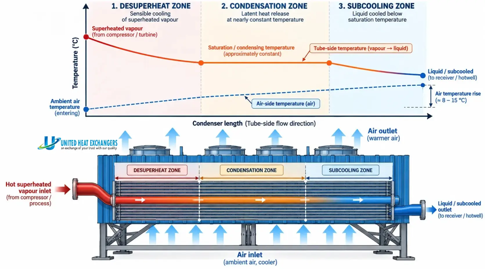
Inside the tubes, vapour moves through three distinct thermal zones. Understanding them explains most design decisions.
Superheated vapour from compressor or turbine
Sensible cooling to saturation
Latent heat released, about 85–90% of duty
Liquid cooled a few degrees below saturation
Liquid to receiver or hotwell
On the air side, fans draw or push ambient air across the fins. Air picks up heat, rising roughly 8–15 °C between inlet and outlet. Because air has low density and low specific heat, a large air volume is needed. That is why these units are wide and fan-heavy, and why fin area matters more than tube count.
The one number that governs everything: ITD
Initial temperature difference (ITD) is condensing temperature minus entering dry-bulb air temperature. Every kelvin of ITD you give the condenser is a kelvin you do not spend on a bigger coil. Designers typically work between 12 and 25 K. Pushing ITD lower shrinks condensing pressure and compressor or turbine back-pressure, but the surface area grows quickly. Choosing ITD is an economic decision, not just a thermal one.
Worked Sizing Example
Assume a refrigeration plant rejecting 500 kW at a design ambient of 38 °C, with an ITD of 15 K.
| Step | Calculation | Result |
|---|---|---|
| Condensing temperature | 38 + 15 | 53 °C |
| Assumed air temperature rise | Design choice | 11 K (air out 49 °C) |
| Air mass flow | Q ÷ (cp × ΔT) = 500 ÷ (1.005 × 11) | about 45 kg/s |
| Air volume flow | 45 ÷ 1.15 kg/m³ | about 39 m³/s |
| LMTD | (15 − 4) ÷ ln(15/4) | about 8.3 K |
| Required UA | 500 ÷ 8.3 | about 60 kW/K |
This is a first-pass estimate. Final selection adds fin efficiency, fouling allowance, altitude derating, fan static pressure and the desuperheat/subcool split. Our engineers run this on every enquiry, and it is the reason a data sheet needs your hottest realistic day, not your annual average.
Types of Air Cooled Condensers
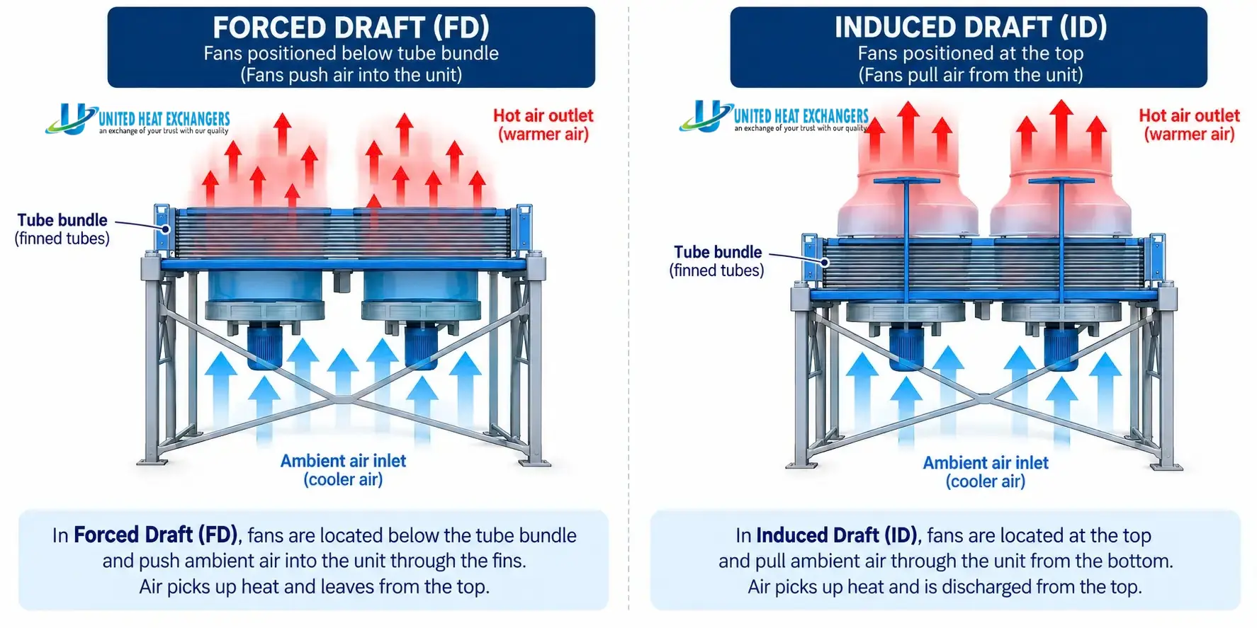
Forced Draft (horizontal)
Fans below the bundle push air up through it. Fans sit in cool air, motors are easy to reach, and it suits most refrigeration and process duties.
Induced Draft
Fans above the bundle pull air through. Air distribution is more even and hot-air recirculation is lower, but fans work in warm air.
A-Frame / V-Frame
Angled coils save footprint and suit large steam or refrigerant duties. Common in power plants and big industrial systems.
Natural Convection
No fans. Buoyancy moves the air. Limited to very small heat loads such as domestic refrigerators.
| Arrangement | Strength | Watch out for | Typical use |
|---|---|---|---|
| Forced draft | Easy fan maintenance, lower cost | Recirculation of hot exhaust air | Refrigeration, chillers, process |
| Induced draft | Uniform airflow, plume lifted away | Fan and motor exposed to hot air | Large industrial duties |
| A-frame | Compact, high capacity | Wind sensitivity, structure height | Steam and power plants |
| Natural convection | Silent, no electricity | Very low capacity | Small appliances |
Construction: Tubes, Fins and Materials
The tube-and-fin combination decides thermal performance, corrosion life and cleanability.
| Element | Options | Choose it when |
|---|---|---|
| Tubes | Carbon steel, stainless steel, copper, aluminium | Match the fluid: steel for steam and hydrocarbons, copper or aluminium for refrigerants |
| Fins | Aluminium (plain, L-foot, embedded, extruded), galvanised steel | Extruded or embedded fins for higher temperatures and better bond; plain aluminium for standard duty |
| Coating | Epoxy, phenolic, or galvanising | Coastal, chemical or high-humidity sites |
| Fin density | Typically 8–11 fins per inch | Lower density in dusty locations; higher where space is tight |
| Fans | Axial, fixed or adjustable pitch, optional VFD | VFDs cut power and noise at part load |
One caution: avoid pairing copper tubes with bare aluminium fins in salt-laden air without protection, because galvanic corrosion shortens coil life.
Air Cooled vs Water Cooled vs Evaporative Condensers
| Factor | Air cooled | Water cooled | Evaporative |
|---|---|---|---|
| Limiting temperature | Dry-bulb | Wet-bulb plus approach | Wet-bulb |
| Water use | None | High, with tower or once-through | Moderate |
| Condensing pressure on hot days | Highest | Lowest | Low |
| Maintenance | Coil cleaning, fan checks | Water treatment, pumps, tower upkeep | Scale, drift and water treatment |
| Best fit | Water-scarce or remote sites | Large, high-efficiency plants | Hot, dry climates with water access |
The real trade is dry-bulb versus wet-bulb. Where water is cheap and treatable, water-cooled systems run cooler. Where it is not, the air cooled condenser wins on lifecycle cost despite higher fan power and footprint.
Where Air Cooled Condensers Are Used
HVAC and chillers
Rooftop units and air cooled chillers for offices, malls, hospitals and data halls.
Refrigeration and cold chain
Cold stores, food processing, dairies and pharmaceutical storage.
Process industries
Condensing solvent, hydrocarbon and chemical vapours where cooling water is limited.
Power generation
Dry cooling of exhaust steam in thermal and combined-cycle plants, including large A-frame arrays.
In steam service the condenser runs under vacuum, so air in-leakage must be removed by ejectors or vacuum pumps. A secondary section (dephlegmator) is often added to push non-condensables out and guard against freezing in winter.
What Quietly Kills Condenser Performance
- Hot-air recirculation: exhaust air re-entering the inlet raises effective ambient. Leave clearance, keep walls and neighbouring units away.
- Fouling: dust, pollen, cottonwood and oily film block fin gaps and raise discharge pressure.
- Non-condensable gas: trapped air in the coil blankets the tube surface and lifts condensing pressure.
- Poor circuiting: uneven vapour distribution leaves tubes flooded or starved.
- Wind: strong crosswinds distort fan inflow, especially on tall A-frames.
As a rule of thumb, each additional kelvin of condensing temperature can add roughly 2–4% to compressor power, depending on refrigerant and system. A dirty coil is therefore a running-cost problem, not just a maintenance one.
Selection Checklist
- Heat rejection duty at the worst realistic ambient, with design margin
- Fluid, pressure, temperature and allowable pressure drop
- Target ITD and condensing temperature
- Site: altitude, dust, coastal air, noise limits, plot space
- Tube, fin and coating materials matched to the environment
- Fan arrangement, VFD requirement and part-load behaviour
- Standards and inspection: ASME Section VIII, API 661 where applicable, third-party inspection
- Access for cleaning and a spares plan for fans, belts and motors
Maintenance and Troubleshooting
| Symptom | Likely cause | Action |
|---|---|---|
| High discharge pressure | Fouled coil, failed fan, recirculation | Clean coil, check fan rotation and clearances |
| Rising power use | Higher condensing temperature | Compare ITD with design and trend monthly |
| Vibration or noise | Fan imbalance, loose guards, bearings | Rebalance, tighten, lubricate or replace |
| Uneven coil temperature | Blocked circuits, trapped gas | Purge non-condensables, inspect distribution |
| Fin damage | Impact, over-aggressive washing | Comb fins, use low-pressure water, never a hard jet |
Wash from the clean (leaving-air) side outward where possible, isolate power first, and keep a quarterly inspection log. In dusty regions, increase the cycle.
Talk to UHE About Your Condenser Duty
Whether you are sizing an A-frame bank for a power plant or replacing a tired condenser on a cold store, the right ITD, fin selection and fan arrangement decide how it performs in peak summer. United Heat Exchangers has been engineering and manufacturing heat transfer equipment in Coimbatore since 1989, and exports to customers worldwide. Send us your duty, fluid and site conditions and our team will propose a configuration.
Request a Technical QuoteFrequently Asked Questions
What is the main advantage of an air cooled condenser?
It rejects heat without consuming water, so there is no cooling tower, no water treatment and no scaling. That makes it practical for remote, arid or water-restricted sites.
How hot can the weather get before it struggles?
Performance depends on dry-bulb temperature. If the unit is sized for your hottest realistic day, it will hold design pressure. If it is sized for an average day, expect high-pressure trips in peak summer.
What is a good ITD for an air cooled condenser?
Most designs fall between 12 and 25 K. Lower values save compressor or turbine energy but need much more surface. The best figure comes from comparing capital cost against energy cost over the equipment life.
Forced draft or induced draft: which should I pick?
Forced draft is simpler to maintain and usually cheaper. Induced draft gives more even airflow and carries hot exhaust air away, which helps in tightly packed layouts.
How often should the coil be cleaned?
Quarterly is a sound baseline. Dusty, coastal or agricultural sites may need monthly cleaning. Track discharge pressure and ITD; a slow upward drift is the clearest sign.
Can the condenser be customised?
Yes. Tube metallurgy, fin type, coating, circuiting, fan arrangement and header design can all be tailored to the fluid, pressure and site. UHE builds to your data sheet rather than a fixed catalogue size.