Table of Contents
- What Is a Fin Fan Cooler? — The Plain Engineering Answer
- Why Fin Fan Coolers Exist — The Problem They Solve
- How a Fin Fan Cooler Works — Heat Transfer Explained
- Key Components — What's Inside Every Unit
- Forced Draft vs. Induced Draft — The Critical Configuration Decision
- Fin Tube Types — The Heart of the Heat Transfer Surface
- Header Box Types — API 661 Configurations
- What Determines Fin Fan Cooler Performance?
- Fin Fan Cooler vs. Water-Cooled System — Honest Comparison
- Industrial Applications — Where Fin Fan Coolers Work
- How to Select the Right Fin Fan Cooler
- API 661 — The Governing Standard
- Maintenance — Keeping a Fin Fan Cooler at Peak Performance
- United Heat Exchangers — Fin Fan Cooler Manufacturer in India
- Frequently Asked Questions

What Is a Fin Fan Cooler?
A fin fan cooler is an air-cooled heat exchanger that removes heat from a hot process fluid using ambient air. Hot fluid flows through finned tubes while motor-driven fans force air across the fins, carrying heat away to atmosphere. The process fluid and air never contact each other.
That's the entire operating principle. No water circuit. No cooling tower. No water treatment. No blowdown discharge permit. One unit, one power connection, one oil inlet and outlet — and it handles your process cooling duty for 35 years with nothing more demanding than periodic fin cleaning and fan bearing lubrication.
Why the name "fin fan cooler"? The name combines the two features that make the design work: the fins on the tube outer surface — which multiply the air-side heat transfer area by 10–20× compared to bare tubes — and the fans that force enough air across those fins to remove the full process heat duty. Neither the fins nor the fans alone is sufficient. Together, they overcome the fundamental limitation of air-cooled heat transfer: air's inherently low density and thermal conductivity.
Why Fin Fan Coolers Exist — The Problem They Solve
To understand why fin fan coolers matter, you need to understand what they replace — and what they cost to replace it.
A conventional water-cooled process cooling system is a chain of equipment: a shell-and-tube heat exchanger, a circulating water pump, supply and return headers, a cooling tower, a make-up water system, a chemical dosing skid for scale, corrosion, and biocide control, a blowdown handling system, and an environmental permit for the discharge. That chain costs money to build, consumes water continuously, requires a trained operator to manage the chemistry, and carries a permanent Legionella risk in the cooling tower.
💡 The real comparison: A 50 MW process cooling duty served by a water-cooled system consumes roughly 2,000–3,000 gallons of cooling water per minute through evaporation and blowdown — over 1 billion gallons per year. A fin fan cooler delivering the same duty consumes zero gallons. For a plant in a water-scarce region, offshore platform, remote gas field, or zero-liquid-discharge facility, this is not an engineering preference. It is the only viable option.
Fin fan coolers solve the problem of process cooling when water is unavailable, impractical, environmentally restricted, or too expensive over the plant life to justify the infrastructure. That covers a very large fraction of all new industrial cooling applications globally — and the share is growing as water stress increases and environmental regulations tighten.
How a Fin Fan Cooler Works — Heat Transfer Explained

The fin fan cooler operates through three sequential heat transfer mechanisms — convection inside the tubes, conduction through the tube wall and fins, and forced convection on the air side. Understanding each step explains both why the design works and where performance problems originate.
The Fundamental Temperature Constraint — Read This Before You Specify
⚠ The minimum outlet temperature rule: A fin fan cooler cannot cool a process fluid below the ambient air dry-bulb temperature at the site. In a well-designed unit, the practical minimum process outlet temperature is approximately 15–25°F (8–14°C) above the maximum design ambient temperature. This is not a limitation of the manufacturer — it is a fundamental thermodynamic constraint. If your process requires an outlet temperature closer to or below the ambient air temperature (for example, chilling a gas below the dew point), a refrigerated or chilled-water cooling system is required, not a fin fan cooler. Always confirm this constraint before selecting air cooling.
Key Components — What's Inside Every Fin Fan Cooler
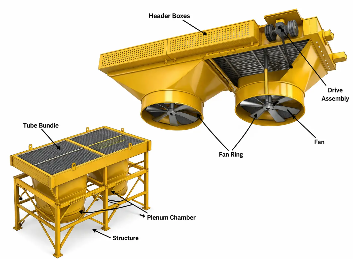
Heat transfer surface
Fluid distribution
Air mover
Motor + gearbox/belt
Air distribution
Steel frame
Airflow control
Fan protection
| Component | Role | Engineering Detail That Matters |
|---|---|---|
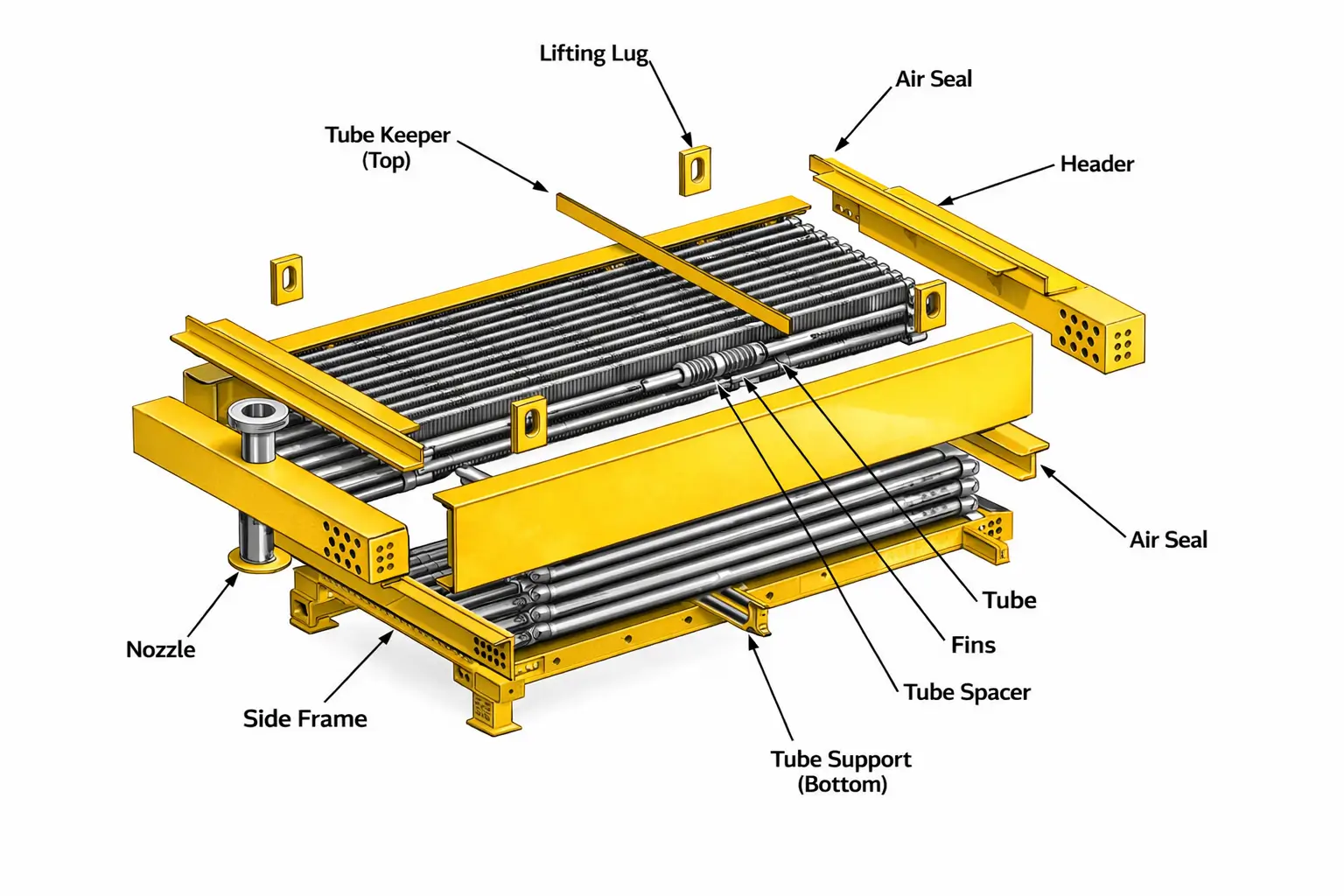
| Finned Tube Bundle | The primary heat transfer surface — process fluid inside, air outside across the fins | Typical bundle: 3–6 tube rows deep, 7–11 fins per inch, tube pitch 2.375–2.5 in on square or triangular arrangement. More rows = more surface area but higher air-side pressure drop requiring more fan power |
| Header Boxes | Distribute process fluid into tube passes at the inlet end and collect cooled fluid at the outlet end; form the tube-side pressure boundary | API 661 defines four standard header types: plug type (most common in refinery service — individual tube access without opening the header), cover plate (removable face plate for full tube-end access), manifold, and box header. Header type selection determines tube maintenance access strategy |
| Axial Flow Fans | Generate the airflow required to remove the process heat duty at the design ambient temperature | Fan coverage ratio: 40–60% of bay face area per API 661 minimum. Fan tip speed: limited to 12,000 ft/min (61 m/s) by API 661 to control noise and structural blade loading. Large-diameter (8–18 ft), low-speed fans move high air volumes at low pressure drop — essential for the low static pressure (0.1–0.5 in W.G.) of fin bundle airflow |
| Fan Drive System | Transmit motor power to the fan at the correct speed | Three options: V-belt drive (low cost, requires monthly tensioning, suitable to ~50 hp); right-angle gearbox drive (higher cost, essentially maintenance-free, preferred for API 661 service above 50 hp); direct drive with variable frequency drive (VFD) for maximum energy efficiency and precise temperature control |
| Plenum Chamber | The sheet-metal enclosure between the fan and the tube bundle that converts the high-velocity fan jet into a uniform low-velocity airstream across the full bundle face | Plenum depth and geometry determine air velocity distribution uniformity across the bundle face. Non-uniform velocity creates hot spots in the bundle and degrades thermal performance — poor plenum design is a frequent root cause of underperformance in improperly engineered units |
| Support Structure | Carries the dead weight of bundles, fans, and motors; resists wind, seismic, and fan vibration dynamic loads | Designed per AISC LRFD or ASD with wind loads per ASCE 7; hot-dip galvanized for 35+ year corrosion protection in most environments; one fixed and one sliding saddle on each bundle to allow free thermal expansion |
| Louvers | Adjustable blade assembly at the air inlet or outlet — throttle airflow to prevent over-cooling of the process in cold weather | Manually or automatically actuated; automatic louvers driven by pneumatic or electric actuators controlled by the process outlet temperature; mandatory for winter operation in cold climates where over-cooling or freeze-up is a risk |
| Vibration Switch | Trips the fan motor if vibration exceeds the alarm setpoint — protects against catastrophic fan blade failure | Mandatory per API 661 on all fans; accelerometer-type sensor on fan bearing housing; trip setpoint established from baseline vibration measurement at commissioning; function-tested at every scheduled maintenance interval |
Forced Draft vs. Induced Draft — The Critical Configuration Decision
The draft arrangement — whether fans push air from below or pull air from above — is the most consequential configuration decision in any fin fan cooler project. It affects fan maintenance access, air distribution quality, hot-air recirculation risk, process outlet temperature achievability, and structural cost. There is no universally correct answer; there is only the answer that best fits your specific operating environment and process criticality.
⇧ Forced Draft
Fans below bundle — air pushed upward through fin surface- Fan and motor access: Fans at grade or low elevation — maintained from ground level without scaffolding or crane; the single biggest practical maintenance advantage
- Power consumption: Fan draws in cool, dense ambient air — higher air density means better fan efficiency and lower motor power for a given airflow rate
- Noise: Fan operates in cooler inlet air — aluminum or FRP blades run more quietly than in induced draft where blades are in the hot exit air stream
- Recirculation risk: Warm exhaust air discharged at low velocity from the top of the bundle can be recirculated back to the fan inlet — especially in tight plot layouts or with prevailing crosswinds that deflect the exhaust; reduces effective cooling on hot still days
- Air distribution: Less uniform velocity profile across the bundle face compared to induced draft — the fan jet must spread uniformly across the full bundle width in the plenum before hitting the tubes
- Structural height: Lower overall structure height — bundle is at the top, fans at the bottom; reduces structural steel cost vs. induced draft for the same bay dimensions
- Best for: General process coolers, condensers, and product coolers in open plot layouts where recirculation is not a concern; the default choice for 70–75% of all refinery and gas plant fin fan cooler installations
⇩ Induced Draft
Fans above bundle — air pulled upward through fin surface- Air distribution: The bundle acts as a flow straightener before the air reaches the fan — produces a more uniform velocity profile across the bundle face; improves bundle thermal performance per square foot of bundle area
- Recirculation resistance: Hot exhaust air exits the top of the structure at high velocity — driven by the fan, it rises quickly away from the unit even in crosswind conditions; significantly reduces recirculation risk in congested plot areas
- Process outlet temperature: Process fluid is at its hottest at the air inlet face (bottom of bundle) and exits at the coolest air temperature point (near the fan at the top) — allows closer approach to ambient temperature in the cooled fluid
- Fan and motor access: Fans at elevated location — require access platforms, elevated walkways, or crane for maintenance; increases maintenance cost and planning complexity vs. forced draft
- Hot air at fan blades: Fan operates in the warm exhaust air stream — blade, bearing, and motor temperatures are higher; requires high-temperature-rated components for process temperatures above 300°F
- Structural height: Taller structure than equivalent forced draft — fan deck is above the bundle, adding height and structural steel cost
- Best for: Critical services where recirculation must be eliminated; close temperature approach requirements; high-ambient-temperature sites; gas compression aftercoolers and overhead condensers where stable air distribution is essential to consistent performance
💡 Which should you specify? Start with forced draft as the default — it is the lower-cost, lower-maintenance option and is adequate for the majority of applications. Switch to induced draft when: (1) the plot layout is congested and hot air recirculation from adjacent equipment is a confirmed risk; (2) the process outlet temperature requirement is within 10–15°F of the maximum ambient temperature; (3) the service is designated critical and the process is sensitive to outlet temperature fluctuations; or (4) the cooling duty is a gas compression aftercooler or column overhead condenser where performance stability is paramount.
Fin Tube Types — The Heart of the Heat Transfer Surface
The fin tube is the single most important component in a fin fan cooler. The fin type — how fins are attached to the bare tube, what material they are made from, and what maximum temperature they can sustain — determines thermal performance, service life, and maintenance requirements over the full plant lifetime. Specifying the wrong fin type is one of the most costly and hard-to-fix errors in fin fan cooler procurement.
Embedded (KLM) Fins
Max: 250°F (121°C)An aluminum strip is wound helically under tension into a machined groove on the tube surface, then the groove edge is crimped over the fin foot — creating a mechanical lock. Simple, low-cost, reliable below 250°F.
▶ Best for: Low-temperature gas coolers, condensers, product coolers below 250°F where the most economical fin type is acceptable.
Extruded Bimetallic Fins
Max: 300°F (149°C)An aluminum sleeve is co-extruded over the base tube, and the fin profile is formed in the same extrusion step — creating an aluminum outer layer metallurgically bonded to the tube with zero contact resistance between fin and tube.
▶ Best for: Moderate-temperature clean services where maximum thermal performance is required — zero contact resistance means the theoretical maximum heat transfer efficiency for air-cooled fins.
L-Foot Tension-Wound Fins
Max: 300°F (149°C)Aluminum strip with an L-shaped foot is tension-wound onto the tube, with the foot bent flat against the tube surface for a larger contact area than a plain wound strip. Better resistance to fin loosening from thermal cycling than plain tension-wound.
▶ Best for: Moderate-temperature services where cost is a constraint and the extended contact area of the L-foot provides adequate joint stability.
Knurled LL-Foot Fins
Max: 400°F (204°C)The tube surface is mechanically knurled before winding, creating an interlock between the fin foot and the tube outer surface that resists fin loosening at elevated temperatures — the best tension-wound option for refinery overhead service.
▶ Best for: Refinery overhead condensers and process coolers operating in the 300–400°F range where embedded and L-foot fins lose contact integrity.
Welded Steel Fins
Max: 600°F+ (315°C+)Carbon steel or stainless steel fins are continuously welded to the base tube by resistance welding or furnace brazing — a permanent metallurgical bond with zero contact resistance and no temperature limit imposed by fin adhesion. Required for the highest-temperature services.
▶ Best for: Hot oil coolers, reactor effluent coolers above 400°F, and services in marine or coastal atmospheres where aluminum fins corrode.
Serrated / Spine Fins
Max: 300°F (149°C)Fins with serrations, notches, or spine patterns cut into the aluminum surface — disrupting the laminar air boundary layer and increasing the air-side heat transfer coefficient by 20–40% over plain fins. Higher air-side pressure drop is the trade-off.
▶ Best for: Space-constrained installations where maximum heat transfer per square foot of plot area is more important than minimizing fan power consumption.
💡 The fin selection mistake that costs the most: Specifying embedded (KLM) fins for a service above 250°F is the single most common and costly fin type error. At temperatures above 250°F, the aluminum softens and loses the compressive contact force that holds it in the groove. The fin-to-tube contact resistance rises, heat transfer degrades, and you have a unit that cannot reach its rated duty — but the fins look visually intact. The only fix is retubing the entire bundle. Always verify the maximum tube wall temperature — not just the process inlet temperature — before specifying fin type.
Header Box Types — API 661 Standard Configurations
The header box is the pressure-containing inlet and outlet manifold that routes process fluid into and out of the tube bundle. API 661 defines four standard configurations, each with a different philosophy for balancing tube-end access, containment integrity, and capital cost.
| Header Type | API 661 | Construction | Tube Access | Best For |
|---|---|---|---|---|
| Plug Type | Type I | Solid welded header with individual threaded plugs directly opposite each tube end — remove one plug to access one tube without opening the header | Per-tube access — no pressure boundary opening; can address any individual tube without affecting adjacent tubes | Refinery and petrochemical service per API 661; high-value or hazardous fluids where full header opening is undesirable; services requiring individual tube plugging during operation |
| Cover Plate Type | Type II | Removable flat face plate bolted to the header box — remove the single cover plate to expose all tube ends simultaneously | Full header opening — all tube ends exposed at once; fastest access for mechanical tube cleaning or inspection of all tubes in one opening | General process service with moderate fouling; services requiring periodic full tube bundle hydro-blast or brush cleaning; lower-pressure applications where full header opening is practical |
| Manifold Type | Type III | Cylindrical pipe manifold directly connected to tube ends via individual stubs — no rectangular header box; each tube connects individually to the manifold pipe | No tube-end access without cutting — used only for fully welded, non-cleanable, clean-service applications | Very high-pressure services where rectangular header box wall thickness becomes prohibitive; clean process fluids where tube cleaning will never be required |
| Box Header | Type IV | Rectangular box header with thicker, more heavily reinforced construction — may be removable-cover or fully welded depending on service | Cover plate removal if removable-cover specified; otherwise cut-and-weld access | High-pressure, high-temperature services requiring both mechanical strength and some degree of tube access; common on high-pressure gas compression aftercoolers |
What Determines Fin Fan Cooler Performance?
A fin fan cooler's thermal performance at any point in time is the product of five interacting variables. Understanding what each variable controls — and how it can degrade — is essential for both specifying a unit correctly and diagnosing performance loss in service.
The single external variable the designer cannot control but must design for. Performance degrades linearly as ambient temperature rises — because the temperature driving force between the process fluid and the cooling air shrinks. Always design for the hottest day of the year at the site, not the annual average. Every degree of underestimation translates directly into process outlet temperature exceedance at peak demand.
The speed at which ambient air moves across the fin surface — set by fan airflow rate divided by the bundle face area. Higher face velocity increases the air-side heat transfer coefficient and removes more heat per unit of fin surface area. But it also increases air-side pressure drop, requiring more fan power. HTRI thermal design finds the optimum balance for each specific duty.
Each row of tubes adds heat transfer surface area. But air heats up as it passes through each successive row — the temperature driving force decreases row by row. This means the fourth and sixth rows are progressively less effective than the first and second. For most duties, 4–6 rows provides the optimum balance between surface area, fan power, and bundle depth.
Dust, oily aerosols, pollen, and industrial particulates accumulate between fin passages over time, partially blocking airflow and insulating the metal surface. A fin surface with only 20% coverage of foulant can reduce the air-side heat transfer coefficient by 30–40%. This is the most common cause of in-service performance degradation — and the most easily corrected.
Oil viscosity, gas density, condensing load, and allowable pressure drop all influence the tube-side heat transfer coefficient and the number of tube passes required. Heavy oils require multi-pass arrangements to maintain adequate velocity; condensing services require specialized thermal design to handle the two-phase flow distribution; high-pressure gas services require thick tube walls that increase conduction resistance.
When warm air exhausted from the top of the fin fan cooler is drawn back into the fan inlet — instead of being replaced by fresh ambient air — the effective inlet air temperature rises above the actual ambient. Even a 5°F rise in effective inlet temperature can cause a 5–10°F rise in process outlet temperature. Recirculation is caused by wind, adjacent hot surfaces, and congested plot layouts — addressed by design through induced draft selection, recirculation baffles, or plot layout management.
Fin Fan Cooler vs. Water-Cooled System — An Honest Comparison
This comparison gets misrepresented in both directions — by water-cooling advocates who ignore infrastructure cost and by air-cooling advocates who ignore the fundamental temperature limitation. Here is the straight engineering picture.
| Attribute | Fin Fan Cooler | Water-Cooled Shell & Tube + Cooling Tower |
|---|---|---|
| Cooling medium | Ambient air — free, unlimited, requires no supply infrastructure | Cooling water — requires tower, pumps, make-up water, chemical treatment, blowdown handling |
| Minimum process outlet temperature | Limited to ~15–25°F above ambient dry-bulb temperature — cannot cool below ambient | Can achieve lower outlet temperatures — limited by cooling water temperature (typically 75–95°F supply), which is lower than ambient air on hot days |
| Water consumption | Zero — completely water-free operation | High — 2,000–4,000 GPM per 50 MW of cooling duty through evaporation and blowdown |
| Heat exchanger unit cost | Higher unit cost — finned tube bundle plus fan structure plus fans plus motors | Lower S&T exchanger unit cost — simpler construction, no fan or motor |
| Total installed system cost | Lower total cost when no water infrastructure exists — just the ACHE unit, a power connection, and process piping | High total cost when infrastructure must be built — tower, basin, pumps, headers, treatment systems, discharge permits |
| Water contamination risk in process fluid | Zero — air cannot contaminate the process fluid | Present — a failed tube or plate allows cooling water to enter the process fluid; can cause catastrophic equipment damage for water-sensitive processes |
| Legionella risk | Zero — no water circuit, no Legionella risk or regulatory compliance requirement | Present — cooling tower water is the primary Legionella reservoir in industrial facilities; requires biocide dosing, monitoring, and regulatory reporting |
| Fouling type | Atmospheric dust and debris on fin surface — cleaned by water or air washing; no chemical treatment required | Cooling water scale, biological fouling (MIC), and chemical deposits on tube surfaces — requires periodic mechanical cleaning and ongoing chemical treatment |
| Performance in hot weather | Degrades on hot days — ambient temperature rises, driving force decreases, outlet temperature rises; size for peak ambient | More stable — cooling tower wet-bulb temperature rises less than dry-bulb temperature in summer heat; performance impact is smaller |
| Remote / offshore / mobile suitability | Ideal — operates anywhere with electrical power, regardless of water availability | Not practical without a permanent water supply and treatment infrastructure |
| Environmental discharge permit | None required — zero liquid effluent | Cooling tower blowdown requires water quality permit and treatment in most jurisdictions |
| Specify fin fan when: | Water unavailable, restricted, or expensive; remote or offshore location; ZLD facility; highest priority is operational simplicity and zero contamination risk; outlet temperature can be maintained ≥15°F above maximum ambient | |
| Specify water-cooled when: | Cooling water is abundant and inexpensive; outlet temperature must be near or below ambient air temperature; very large heat load where ACHE plot footprint would be impractically large; enclosed machine room with insufficient ambient air access | |
Industrial Applications — Where Fin Fan Coolers Work
Fin fan coolers are specified in every industry where process cooling is required and water cooling is impractical, uneconomical, or environmentally restricted. The following applications represent the full range of services United Heat Exchangers has engineered and delivered.
| Industry | Specific Fin Fan Cooler Application | Process Fluid | Key Design Requirement |
|---|---|---|---|
| Oil & Gas Refining | Crude distillation overhead condenser; naphtha product cooler; vacuum gas oil cooler; amine cooler; atmospheric residue trim cooler | Light hydrocarbons, naphtha, gas oil, amine solutions | API 661 compliance; knurled LL-foot fins for 300–400°F overhead condenser service; plug-type headers for refinery service; full API 661 documentation package |
| Natural Gas Processing | Sales gas cooler; NGL product cooler; amine lean cooler; glycol (TEG) trim cooler; molecular sieve regeneration gas cooler | Sales gas, NGL, lean amine, glycol | Outlet temperature control — sales gas spec temperature must be maintained at maximum summer ambient; NACE MR0175 for sour gas service; stainless steel tubes for glycol or amine corrosion risk |
| Gas Compression | Interstage and aftercooler for all compression stages; compressor lube oil cooler; compressor jacket water cooler; suction gas scrubber overhead cooler | Compressed gas (all pressures), lube oil, jacket water | High operating pressure on tube side — thick-wall tubes; outlet temperature precisely controlled to avoid condensation ahead of the suction scrubber; ATEX-rated motors for Zone 2 installations |
| Petrochemical | Reactor effluent trim cooler; ethylene plant cracked gas cooler; propylene fractionator overhead condenser; aromatics extraction column overhead | Reactor effluents, ethylene, propylene, aromatics | Polymerization risk (styrene, butadiene) requires careful heat flux and tube skin temperature control; ethylene service requires cryogenic-qualified materials (impact tested at -150°F) |
| Power Generation | Air-cooled condenser (ACC) for steam turbine exhaust; turbine lube oil cooler; closed cooling water cooler; transformer oil cooler | Exhaust steam, lube oil, closed cooling water | ACC must be sized for maximum summer ambient — turbine back pressure directly limits output; VFD fan control for seasonal efficiency optimization; large multi-fan induced draft arrangement standard for ACCs |
| Fertilizer & Ammonia | Ammonia condenser; synthesis gas (H₂/N₂) cooler; urea solution cooler; carbon dioxide stripper overhead cooler | Ammonia, synthesis gas, urea solution, CO₂ | Carbon steel tubes (never copper alloys for ammonia service); ammonia condensers require careful tube-side pressure and temperature control to maintain condensate subcooling; CO₂ service requires corrosion-resistant materials |
| Offshore & Marine | Wellhead production gas cooler; gas export cooler; production separator overhead; deck crane hydraulic oil cooler; gas lift compressor aftercooler | Wet crude, production gas, associated gas, hydraulic oil | Compact layout for weight and space optimization; ATEX Zone 1/2 electrical classification; marine-grade coatings on structure and fins (SS or galvanized fins, epoxy-coated structure); vibration resistance for deck-mounted installation |
How to Select the Right Fin Fan Cooler
A correct fin fan cooler specification starts with five decisions — made in order, before you ever send an enquiry to a manufacturer. Getting these right means the unit you receive performs to specification on day one and every summer peak day for the next 25 years.
Decision 1 — Design Ambient Temperature
This is the most critical input and the most commonly underestimated. The design ambient temperature must be the maximum dry-bulb air temperature at the installation site during operating periods — not the annual average, not the average summer temperature, not the 10-year mean. It should be the 99th percentile design dry-bulb temperature from a meteorological database for the specific site location. For sites in enclosed buildings, add 10–20°F to the outdoor ambient to account for heat buildup in the building space.
Decision 2 — Draft Arrangement
Use the criteria from Section 5 to decide between forced and induced draft. Default to forced draft unless one or more of the induced draft triggers applies. Document the basis for your decision — it will be revisited if the unit underperforms.
Decision 3 — Fin Tube Type
Determine the maximum tube wall temperature at design operating conditions — not the bulk fluid inlet temperature. The tube wall temperature can be significantly higher than the fluid temperature in condensing or high-flux services. Use the maximum tube wall temperature to select the appropriate fin type from Section 6. If uncertain, specify one temperature grade above the calculated requirement as a safety margin — the cost difference between fin types is small compared to the cost of a retube.
Decision 4 — Header Box Type
For all petroleum and petrochemical services, specify plug-type headers (Type I) per API 661 as the default. For general process and utility services where periodic full tube-bundle hydro-blast cleaning is the maintenance approach, cover-plate headers (Type II) are acceptable and lower cost.
Decision 5 — Fan Speed Control Strategy
- Fixed speed, no temperature control: Lowest cost. Acceptable only when the ambient temperature never approaches the design maximum and over-cooling of the process fluid is harmless (no freezing, no minimum process temperature). Not recommended for critical services.
- Thermostat-switched fan: Fan runs at full speed above the setpoint and stops below it. Simple and inexpensive, but causes abrupt temperature cycling between fan-on and fan-off. Acceptable for non-critical services with wide tolerable process temperature ranges.
- Two-speed motor: Fan runs at full speed in summer, half-speed in mild weather. Reduces energy consumption by up to 75% at half-speed (fan power scales with speed cubed). A good low-cost compromise for services with clearly defined seasonal load variation.
- Variable frequency drive (VFD): Fan speed modulates continuously to maintain a precise process outlet temperature setpoint regardless of ambient temperature or heat load variation. Maximum energy efficiency and process temperature stability. Specify for all critical services and any new installation where lifecycle energy cost is evaluated.
API 661 — The Governing Standard for Fin Fan Coolers
API Standard 661 — Air-Cooled Heat Exchangers for General Refinery Service — is the design, fabrication, inspection, testing, and documentation standard that governs all fin fan coolers supplied to petroleum refining, petrochemical, and natural gas processing industries. It is not a guideline. For these industries, it is the baseline specification — referenced in purchase orders, applied to all vendor documentation, and enforced through third-party inspection.
What API 661 Specifically Requires
- Tube bundle pressure design per ASME BPVC Section VIII — all pressure-containing tube bundle components (header boxes, tubes, nozzles) must be designed, fabricated, and U-Stamped per ASME Section VIII Division 1 or 2
- Fan tip speed limit of 12,000 ft/min (61 m/s) — controls noise generation and blade structural loading; design to lower tip speeds (8,000–10,000 ft/min) when noise limits are specified
- Minimum fan coverage ratio of 40% of bay face area — ensures adequate airflow distribution uniformity across the tube bundle
- Vibration switch on every fan — mandatory fan protection; accelerometer-based trip on high vibration; trip setpoint set from baseline commissioning data
- Flow-induced vibration analysis — mandatory for all tube bundles; verifies that no tube natural frequency coincides with the forcing frequencies from airflow turbulence or adjacent fan operation
- Full vendor data package — completed API 661 data sheets, thermal design calculations, structural calculations, fan performance test data, material certifications, NDE records, and ASME documentation
- Nozzle load resistance — header boxes and structure must be designed to resist the external piping loads specified in the purchase order without exceeding allowable stresses
- Class 1 special service requirements — for lethal, toxic, or flammable-at-conditions fluids: plug-type headers mandatory, strength-welded tube-to-tubesheet joints, enhanced NDE on all pressure welds, witnessed hydrostatic testing
Maintenance — Keeping a Fin Fan Cooler at Peak Performance
A well-maintained fin fan cooler operates at rated thermal performance for 25 years. The maintenance requirements are genuinely simple compared to water-cooled systems — but ignoring them, particularly fin surface cleaning, directly degrades cooling performance and can cause cascading problems in the process upstream.
Daily / Weekly Performance Monitoring
- Process outlet temperature vs. design performance curve: The design performance curve supplied with every United Heat Exchangers unit shows the expected outlet temperature at each ambient temperature. If the measured outlet temperature is running consistently 5–10°F above the curve at the current ambient, fin fouling or reduced airflow is the cause — investigate promptly before the process trips on high temperature.
- Fan motor amperage: Rising amperage at constant ambient and process conditions indicates increasing air-side resistance — almost always from fin fouling. Falling amperage on a belt-driven unit indicates belt slip.
- Fan vibration readings: Any step-change in vibration above the baseline measurement taken at commissioning requires immediate fan shutdown and inspection. Fan blade damage or pitch angle inequality between blades can cause vibration that, if unchecked, leads to hub fatigue failure and catastrophic fan disintegration.
Monthly Maintenance
- Fin surface visual inspection: Inspect from the walkway above the bundle and from below (forced draft). Dust, pollen, oily aerosols, and industrial particulates gradually fill the fin passages. In dusty or oily atmospheres (steel mills, cement plants, near roads), monthly cleaning may be required to maintain performance.
- V-belt inspection (belt-drive units): Check tension, re-tension if deflection exceeds specification, replace any belt showing glazing or cracking. A loose belt slips under load, reducing fan speed by 10–20% and airflow by 25–50%.
- Fan blade pitch angle: Verify all blades on all fans are set to the same pitch angle (±0.5°). Unequal pitch creates both vibration and unequal thrust on the hub — causes premature bearing fatigue and noise.
Quarterly / Annual
- Fin surface cleaning: High-pressure water wash in the direction opposite to airflow (i.e., from the top of the bundle downward on a forced draft unit) to dislodge embedded debris. For oily or greasy deposits, mild alkaline degreaser solution followed by water rinse. Never use high-pressure jets directly on fin surfaces — the fin material is thin and soft; mechanical damage is irreversible.
- Bearing lubrication: Re-grease fan shaft bearings per the bearing manufacturer's lubrication schedule using the specified grease type and quantity. Follow the schedule exactly — both over-greasing and under-greasing cause premature bearing failure.
- Gearbox oil change: Drain and replace gearbox oil per manufacturer's schedule (typically every 2–4 years). Send oil sample for elemental analysis to detect bearing and gear wear metals before a failure develops into an incident.
Turnaround Inspection (Every 3–5 Years)
- Eddy current or IRIS tube inspection through open header plugs or cover plate — detect tube wall thinning, pitting, and erosion before through-wall failures occur; re-inspect previously marginal tubes at each outage to track remaining life
- Fan blade dye-penetrant (PT) inspection at blade root and hub attachment — fatigue cracks initiate at the highest-stress location; detect and replace cracked blades before an in-service failure
- Pressure test tube bundle at 1.5× design pressure after any header opening — confirm all tube-to-tubesheet joints are leak-tight before returning to service
- Structural inspection — check all connection bolts, weld seams on structural members, and galvanizing condition; re-touch-paint any areas of galvanize loss immediately
United Heat Exchangers — Fin Fan Cooler Manufacturer in India
United Heat Exchangers has designed and fabricated fin fan coolers for refinery overhead condensers, gas compression trains, petrochemical reactor effluent coolers, offshore production platforms, and power generation air-cooled condensers across India, the Middle East, Southeast Asia, and Africa — for 35+ years.
⚙ What We Deliver with Every Fin Fan Cooler
Certified Design
All Tube Bundles
Thermal Guarantee
Per API 661
No Missing Documents
Budgetary Quote
Every unit is thermally designed using HTRI Xchanger Suite. The process outlet temperature at the design ambient temperature is confirmed in writing and backed by our engineering team. We do not issue "estimated" performance figures.
We use your site's actual maximum dry-bulb ambient temperature — from your meteorological data or industry databases for your location — not a generic number. Your unit will perform to specification on the hottest day of the year.
API 661 data sheets, thermal calculations, vibration analysis, fan performance test data, ASME U-Stamp documentation, structural calculations, MTRs, NDE records — complete and submitted on schedule. No document re-work delays at project handover.
Tube bundles, header boxes, fan stacks, fans, motors, drive systems, structure, access platforms, louvers, vibration switches, winterization coils — all engineered, supplied, and tested under one contract and one quality system.
Get a Free Fin Fan Cooler Quote in 48 Hours — From India's Trusted Manufacturer
Share your process fluid, heat duty, required outlet temperature, maximum site ambient, and applicable codes — and our engineering team will size the right forced or induced draft unit, select the correct fin type, and deliver a fully itemized API 661 proposal within 48 hours.
Request My Free Quote →Frequently Asked Questions About Fin Fan Coolers
What is a fin fan cooler?
A fin fan cooler — formally called an air-cooled heat exchanger (ACHE) — is a heat exchanger that removes heat from a hot process fluid by passing it through finned tubes while motor-driven fans force ambient air across the fin surfaces. The fins multiply the air-contact surface area by 10–20× compared to bare tubes, compensating for air's inherently low heat transfer coefficient. The result is a cooling system that uses no water, produces no liquid waste, and operates wherever electricity is available — regardless of water supply.
What is the difference between a forced draft and an induced draft fin fan cooler?
In a forced draft fin fan cooler, fans are located below the tube bundle and push ambient air upward through the fin surface. Advantages: fans at grade level for easy maintenance, lower motor power consumption, lower structure cost. Disadvantage: higher risk of hot air recirculation at the fan inlet. In an induced draft design, fans are above the bundle and pull air through from below. Advantages: more uniform air velocity across the bundle, lower recirculation risk, better performance in high-ambient-temperature conditions, closer process outlet temperatures. Disadvantage: fans at elevated location requiring platform access for maintenance, higher structure cost. Forced draft is the default for most applications; induced draft is specified for critical services and high-ambient sites.
What is the minimum outlet temperature a fin fan cooler can achieve?
A fin fan cooler cannot cool a process fluid below the ambient dry-bulb air temperature at the site — this is a fundamental thermodynamic constraint, not a design limitation. In a well-designed unit, the minimum practical process outlet temperature is approximately 15–25°F (8–14°C) above the maximum design ambient temperature. If you need a process outlet temperature closer to or below the ambient temperature, a refrigerated cooling system or chilled-water system is required.
What is API 661 and why does it matter for fin fan coolers?
API Standard 661 is the governing design, fabrication, inspection, and documentation standard for air-cooled heat exchangers in petroleum refining, petrochemical, and natural gas processing service. It specifies header box types, fan tip speed limits, fan coverage ratios, vibration switch requirements, flow-induced vibration analysis, nozzle load resistance, tube-to-tubesheet joint requirements for Class 1 service, and the full vendor data documentation package. For all oil and gas industry applications, API 661 compliance is not optional — it is a standard purchase order requirement.
What are the main fin tube types used in fin fan coolers?
The six main types are: embedded (KLM) — aluminum fins mechanically locked in tube groove, max 250°F; extruded bimetallic — aluminum sleeve co-extruded over tube, zero contact resistance, max 300°F; L-foot tension-wound — aluminum strip with L-shaped foot, max 300°F; knurled LL-foot — tension-wound with knurled tube surface for better contact at higher temperatures, max 400°F; welded steel — continuously welded carbon or stainless steel fins, no temperature limit from fin attachment, max limited only by tube material; serrated/spine — aluminum fins with notched surfaces for higher air-side heat transfer coefficient, max 300°F.
How is a fin fan cooler different from a cooling tower?
A fin fan cooler directly cools process fluid inside sealed tubes using dry ambient air — the fluid and air never make contact. A cooling tower cools recirculating water by evaporation — water is sprayed into the air, a fraction evaporates, and the rest is cooled. Fin fan coolers consume no water and produce no water discharge; cooling towers consume large volumes of water through evaporation and blowdown and require chemical treatment. Cooling towers can achieve lower effective cooling temperatures (based on wet-bulb temperature, which is lower than dry-bulb on hot humid days), but at the cost of water consumption and infrastructure complexity.
What information do I need to provide to get a fin fan cooler quote?
The essential inputs are: (1) process fluid name and composition; (2) heat duty in kW or BTU/hr; (3) fluid inlet temperature and required outlet temperature; (4) design pressure and allowable pressure drop; (5) maximum site ambient dry-bulb temperature; (6) site altitude above sea level; (7) forced draft or induced draft preference (or ask our team to recommend based on your plot conditions); (8) applicable design code (API 661, ASME, PED, IS); (9) hazardous area electrical classification if applicable; (10) any special requirements (noise limit, winterization, VFD control). Our engineering team will complete the full HTRI thermal design and return a budgetary proposal within 48 hours.
Author: Senthil Kumar, Technical Director — United Heat Exchangers Pvt. Ltd. | Last Updated: March 2026 | Related: Air Cooled Heat Exchanger | Fin Fan Cooler Product Page | Air Cooled Condenser