Author: Senthil Kumar, Technical Director | Updated: June 2026
Table of Contents
- What Is a Multitube Heat Exchanger?
- How a Multitube Heat Exchanger Works — The Engineering Principle
- Types and Flow Arrangements of Multitube Heat Exchangers
- Multitube Heat Exchanger Anatomy — Key Components
- Tube Bundle Layout — Pitch, Configuration, and Baffling
- Engineering Advantages of Multitube Heat Exchangers
- Design Specifications and Standards
- Material Selection Guide — Tubes, Shell, and Baffles
- Innovations in Multitube Heat Exchanger Design
- Industries and Applications
- Multitube vs Double-Pipe Heat Exchanger
- How to Select a Multitube Heat Exchanger
- Maintenance Tips and Cleaning Guide
- Why United Heat Exchangers
- Delivery and What's Included
- Frequently Asked Questions
What Is a Multitube Heat Exchanger?
A multitube heat exchanger is a type of heat transfer device consisting of multiple smaller tubes that are bundled together within a larger shell. These tubes allow two fluids — one hot and one cold — to exchange heat efficiently without mixing. Heat moves from the heated fluid to the colder fluid that circulates around the tubes via the tube walls, with the tube wall material and thickness chosen specifically to permit efficient conduction while keeping the two fluid streams completely separate and contained at their respective design pressures.
The multitube design is particularly effective in situations where high heat transfer rates are needed and where space constraints are a concern. Rather than using one or two large-diameter tubes — which provide relatively little surface area per unit of shell volume — a multitube heat exchanger subdivides the same total flow area into dozens, hundreds, or even thousands of smaller tubes. This subdivision multiplies the wetted perimeter and surface area available for heat exchange within the same overall shell envelope, allowing a multitube unit to transfer far more heat per cubic meter of installed volume than an equivalent single-tube or double-pipe design.
The heat exchanger's casing — the shell — is frequently constructed to handle high pressure and temperature conditions, and the tubes inside are typically composed of materials like carbon steel, copper, or stainless steel, selected according to the corrosivity, temperature, and pressure of the process fluid. The multitube heat exchanger is suitable for both counter flow and parallel flow configurations, making it adaptable for a wide range of applications across chemical processing, power generation, HVAC, food and beverage, and renewable energy.
As a leading multitube heat exchanger manufacturer in India, United Heat Exchangers designs and fabricates multi tube heat exchangers in stainless steel, copper, carbon steel, and high-conductivity alloys, engineered to deliver superior heat transfer efficiency in both high- and low-temperature conditions. Every unit is thermally rated, pressure-designed to ASME Section VIII, and supplied with full certification and documentation — giving plant engineers confidence in long-term reliability and performance.
How a Multitube Heat Exchanger Works — The Engineering Principle
Multitube heat exchangers work by transferring heat between two fluids flowing in different sections of the system. One fluid passes through the tubes, while the other flows around the tubes within the shell. The heat transfer process occurs as thermal energy from the hotter fluid moves through the tube walls and into the colder fluid — governed by the fundamental relationship Q = U × A × ΔT_mean, where Q is the heat duty, U is the overall heat transfer coefficient, A is the total heat transfer surface area, and ΔT_mean is the mean temperature difference between the two streams.
Engineering Insight — Why More, Smaller Tubes Outperform Fewer, Larger Ones: For a fixed total flow cross-section, subdividing that area into many smaller tubes increases the ratio of wetted surface area to flow volume. A bundle of N tubes each of diameter d has a combined surface area per unit length proportional to N × d, while the combined flow area is proportional to N × d². Halving the tube diameter while quadrupling the tube count keeps the flow area constant but doubles the surface area available for heat exchange — directly increasing A in the Q = U × A × ΔT relationship without enlarging the shell. This is the core reason multitube heat exchangers achieve such high heat transfer efficiency within a compact footprint.
Hot Fluid Enters Tube Side
The hot process fluid flows through the inner tubes, transferring heat outward to the tube walls as it travels the length of the bundle.
Conduction Through Tube Wall
Heat conducts from the hot tube-side fluid through the tube wall thickness. Tube material conductivity and wall thickness determine this resistance.
Cold Fluid Circulates in Shell
Baffles that channel the flow across the bundle for better turbulence and contact direct the cold fluid around the tubes inside the shell.
Convection Absorbs Heat
The shell-side fluid absorbs heat by convection from the outer tube surfaces, with baffle-induced turbulence enhancing the shell-side film coefficient.
Fluids Exit at New Temperatures
The hot fluid exits cooler through the tube outlet nozzle; the cold fluid exits warmer through the shell outlet nozzle, having absorbed the transferred heat.
Heat transfer in a multitube heat exchanger occurs through the walls of the tubes, with the temperature difference between the hot and cold fluids driving the process. Several factors affect the rate of heat transfer, including the thermal conductivity of the tube material, the temperature differential between the fluids, the flow velocity and turbulence of the fluids on both the tube and shell sides, and — most notably for this type of exchanger — the total surface area available for heat exchange, which is optimized by the multitube bundle configuration.
Fluid flow configuration is central to multitube performance. The hot fluid on the tube side flows through the inner tubes, transferring heat to the tube walls, while the cold fluid on the shell side flows around the tubes, absorbing heat from the walls of the tubes. Which fluid is routed through the tubes versus the shell is a deliberate design decision — high-pressure, corrosive, or fouling fluids are typically placed on the tube side, since individual tubes are easier and cheaper to clean, replace, or upgrade in material than the shell itself, and tube-side pressure containment requires less wall thickness per unit area than an equivalent shell.
Types and Flow Arrangements of Multitube Heat Exchangers
United Heat Exchangers manufactures multitube heat exchangers in a range of configurations and flow arrangements, selected based on the process fluids, the temperature approach required, available space, and maintenance access needs.
Counter Flow Multitube Heat Exchanger
Fluids flow in opposite directions — maximum temperature gradient and efficiencyIn a counter flow multitube heat exchanger, the hot and cold fluids travel in opposite directions through the unit. This arrangement maintains a more uniform and generally larger temperature difference along the full length of the exchanger, maximizing the log mean temperature difference (LMTD) and allowing a smaller unit to achieve the same duty as a parallel flow design.
- Highest thermal efficiency of the standard flow arrangements for a given surface area
- Capable of heating the cold fluid to a temperature above the hot fluid outlet — a thermal "cross" not possible in parallel flow
- Preferred default arrangement for most process heating, cooling, and heat recovery duties
- Applications: process fluid coolers, regenerative heat recovery, condensers requiring close temperature approach
Parallel Flow Multitube Heat Exchanger
Fluids flow in the same direction — smaller temperature differences, gentler thermal gradientIn a parallel flow multitube heat exchanger, both fluids enter at the same end and travel in the same direction. The temperature difference is largest at the inlet and narrows progressively along the length of the unit, frequently employed in applications characterized by minimal overall temperature differentials or when a gradual, regulated temperature alteration is preferred for the process or the materials involved.
- Produces a more uniform tube wall temperature along the bundle length, reducing thermal stress in some services
- Useful where rapid initial heating or cooling of a temperature-sensitive fluid must be avoided
- Outlet temperatures of both fluids always converge toward each other but never cross
- Applications: gentle process heating, viscous fluid preheating, services prone to fouling or freezing at high local ΔT
Fixed Tube Sheet Multitube Heat Exchanger
Tube sheets welded directly to the shell — simplest and most economical constructionA fixed tube sheet multitube heat exchanger has both tube sheets welded directly to the shell, forming a rigid, economical construction. The tube bundle cannot be removed from the shell, so shell-side mechanical cleaning is limited to chemical circulation or water jetting through the nozzles rather than physical bundle withdrawal.
- Lowest-cost construction for a given duty among the common TEMA configurations
- No internal joints prone to leakage between shell-side and tube-side fluids
- Best suited to clean shell-side fluids or services where chemical cleaning is adequate
- Expansion joints may be added to the shell to accommodate differential thermal expansion between shell and tubes
U-Tube Multitube Heat Exchanger
Tubes bent into a U-shape with one tube sheet — accommodates thermal expansionA U-tube multitube heat exchanger bends each tube into a U-shape, anchored at only one tube sheet. This design naturally accommodates the differential thermal expansion between the tubes and the shell without need for an expansion joint, and the entire bundle can be withdrawn from the shell for tube-side or shell-side inspection and cleaning.
- Removable bundle simplifies maintenance and full mechanical cleaning of the shell side
- Inherently tolerant of large temperature differences between tube-side and shell-side fluids
- Tube-side mechanical cleaning of the U-bend itself is more difficult than straight-tube designs
- Widely specified for high-temperature-difference duties such as steam heaters and high ΔT process coolers
Floating Head Multitube Heat Exchanger
One tube sheet floats free of the shell — full bundle removal, both sides cleanableA floating head multitube heat exchanger uses a tube sheet at one end that is free to move axially within the shell, fully decoupling tube expansion from shell expansion while still allowing the complete bundle to be withdrawn for cleaning. This configuration is specified when both the tube side and shell side are subject to fouling and require periodic full mechanical cleaning.
- Most versatile and maintenance-friendly configuration for fouling services on both sides
- Accommodates the largest thermal expansion differentials of any standard TEMA configuration
- Higher initial cost and more complex floating head closure compared with fixed tube sheet or U-tube designs
- Applications: heavy fouling chemical process duties, crude and product heat recovery in refineries
Multi-Pass Multitube Heat Exchanger
Tube-side fluid routed through multiple passes — higher velocity, improved coefficientA multi-pass multitube heat exchanger directs the tube-side fluid back and forth through the bundle two, four, or more times using pass partition plates in the header, rather than flowing straight through once. Multiple passes increase tube-side velocity for a given flow rate, improving the tube-side film coefficient at the cost of higher tube-side pressure drop.
- Improves tube-side heat transfer coefficient without increasing the number of tubes
- Allows a more compact shell diameter for a given tube-side flow rate and velocity target
- Increases tube-side pressure drop proportionally to the number of passes — must be checked against allowable ΔP
- Applications: services with low tube-side flow rate relative to duty, where single-pass velocity would be too low for good heat transfer
Multitube Heat Exchanger Anatomy — Key Components
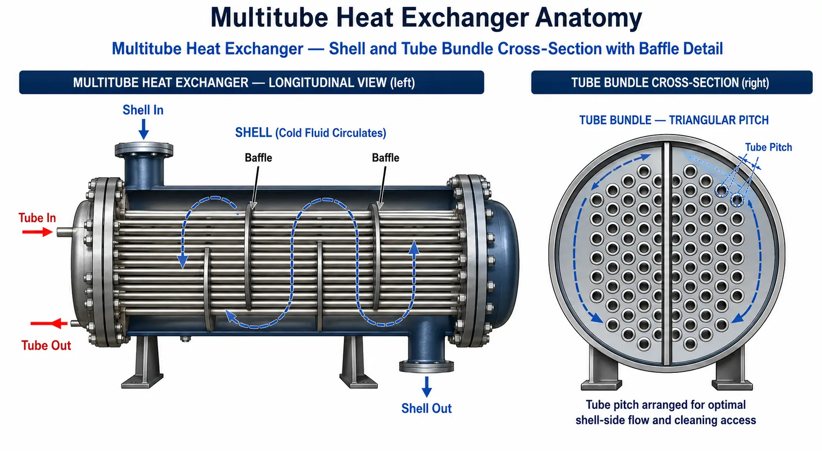
Understanding the main components of a multitube heat exchanger helps in appreciating its design and functionality. Each component plays a defined role in containing the two fluid streams, directing their flow, and supporting the structure under operating conditions.
Tubes
The set of small tubes that transport the heated fluid is the multitube heat exchanger's central component. These tubes are typically made from materials with high thermal conductivity, such as copper or stainless steel. The configuration and pitch of the tubes is optimized to maximize the surface area available for heat exchange while keeping shell-side pressure drop and fabrication cost in check.
Shell
The shell surrounds the tubes and is where the cold fluid circulates. It acts as the containment vessel and is built to withstand the fluid pressure and temperature conditions of the shell-side stream. The shell diameter, length, and nozzle placement are sized around the tube bundle and the required shell-side flow distribution.
Baffles
Baffles are placed inside the shell to direct the flow of the cold fluid, promoting a more turbulent flow that enhances heat transfer. Baffles also help reduce vibration and improve the structural integrity of the exchanger by supporting the tubes at regular intervals along their length, preventing sagging and flow-induced vibration damage.
Inlet and Outlet Nozzles
Inlet and outlet nozzles are critical components for fluid entry and exit on both the tube side and shell side. These connections ensure that the fluids are fed into the system and directed through the appropriate channels, often designed with flanges, threads, or welded connections to prevent leaks at the design pressure and temperature.
Tube Sheets and Support Plates
The exchanger's tubes are held in place by tube sheets at each end and intermediate support plates that ensure proper alignment and prevent shifting under high pressure or temperature conditions. These components are crucial to the structural integrity of the system, especially in lengthy tube bundles that are susceptible to vibration caused by flow.
Insulation (Optional)
For applications requiring temperature regulation, insulation can be added to the shell exterior of the multitube heat exchanger to reduce heat loss to atmosphere, improve overall energy efficiency, and protect personnel from contact with hot external surfaces.
Tube Bundle Layout — Pitch, Configuration, and Baffling
The arrangement of tubes within the bundle — known as the tube pitch and pattern — has a direct effect on heat transfer performance, shell-side pressure drop, fouling tolerance, and ease of cleaning. United Heat Exchangers engineers select the correct pitch and pattern for each multitube heat exchanger based on the shell-side fluid properties and the required cleaning method.
| Tube Pattern | Description | Shell-Side Heat Transfer | Cleanability | Typical Use |
|---|---|---|---|---|
| Triangular Pitch | Tubes arranged at the points of equilateral triangles — the tightest practical packing for a given tube count | Highest — maximum turbulence and surface density per shell diameter | Poor — no straight lanes for mechanical cleaning tools; chemical cleaning only | Clean shell-side fluids; maximum compactness for a given duty |
| Rotated Triangular Pitch | Triangular pattern rotated 30° from the standard orientation, altering the shell-side flow path geometry | High — similar density to standard triangular with a different flow distribution | Poor — same mechanical cleaning limitations as triangular pitch | Alternative flow distribution for specific thermal-hydraulic requirements |
| Square Pitch | Tubes arranged in straight rows and columns, creating clear lanes between adjacent tube rows | Moderate — lower turbulence than triangular at the same pitch ratio | Good — straight lanes allow mechanical tube cleaning tools to pass through the bundle | Fouling shell-side fluids requiring mechanical cleaning access |
| Rotated Square Pitch | Square pattern rotated 45°, presenting tube rows diagonally to the shell-side flow direction | Improved over standard square — better turbulence while retaining cleaning lanes | Good — diagonal lanes still permit mechanical cleaning equipment | Moderately fouling fluids needing both performance and cleanability |
Baffle spacing and cut govern the shell-side flow pattern and pressure drop. Closer baffle spacing increases shell-side velocity and turbulence — improving the shell-side heat transfer coefficient — but also increases pressure drop and the risk of flow-induced tube vibration. TEMA guidelines and detailed vibration analysis are used to set the baffle spacing that balances thermal performance against mechanical reliability for each specific multitube heat exchanger design. Baffle cut — the percentage of the baffle diameter left open for flow — is typically specified between 20% and 35%, with smaller cuts increasing velocity and larger cuts reducing pressure drop at some cost to heat transfer.
Design Tip — Tube Count vs Tube Diameter: For a given total tube-side flow area, a multitube heat exchanger with a higher tube count of smaller-diameter tubes delivers more surface area and generally better heat transfer per unit shell volume than fewer larger-diameter tubes. However, smaller tubes are more susceptible to plugging by particulate in the process fluid and require more careful attention to tube-side velocity to avoid erosion at high flow rates. United Heat Exchangers' thermal design team optimizes tube count, diameter, and length together against the process fluid's fouling tendency and particulate content.
Engineering Advantages of Multitube Heat Exchangers
Multitube heat exchangers provide several key advantages that make them a preferred choice across a wide range of industrial heat transfer duties.
High Heat Transfer Efficiency
The design with multiple tubes increases the surface area available for heat exchange, improving the overall heat transfer coefficient and the total thermal conductance achievable within a given shell envelope, compared with single large-bore tube alternatives.
Compact Design
With multiple smaller tubes, multitube exchangers maintain a compact footprint while handling large volumes of fluids. As a result, they are ideal for applications requiring minimal space, such as crowded process skids and offshore platform layouts.
Versatility in Fluids
These exchangers are adaptable to various types of fluids, including corrosive chemicals, high-viscosity fluids, and temperature-sensitive substances, with tube material, pitch, and pass arrangement individually tailored to each fluid's properties.
Durability
Constructed from strong materials, multitube heat exchangers are capable of handling high pressures and temperatures, making them reliable in challenging industrial environments over decades of continuous or cyclic service.
Energy Savings
Due to their enhanced thermal efficiency, multitube heat exchangers help reduce energy consumption in heating and cooling duties, leading to long-term operating cost savings across the asset's service life.
Flexible Flow Arrangement
The ability to configure counter flow, parallel flow, single-pass, or multi-pass tube-side routing allows the same fundamental multitube design to be tuned precisely to the temperature approach and pressure drop requirements of each application.
Maintainable Construction
U-tube and floating head multitube configurations allow the entire bundle to be withdrawn from the shell for inspection, mechanical cleaning, and tube replacement — minimizing downtime and extending the useful service life of the unit.
Scalable Across Pressure and Temperature Ranges
The same fundamental multitube construction principle scales from atmospheric, low-temperature HVAC duty to high-pressure, high-temperature chemical processing service simply by adjusting tube wall thickness, material, and shell design pressure — without changing the basic engineering approach.
Design Specifications and Standards
Multitube Heat Exchanger — Standard Design Parameters (United Heat Exchangers)
Material Selection Guide — Tubes, Shell, and Baffles
Carbon Steel Tube and Shell
The default, most economical material for multitube heat exchangers in clean, non-corrosive process service — water, steam, non-corrosive hydrocarbons, and compressed air. Suitable for moderate temperature and pressure ranges, with corrosion allowance added where mild atmospheric or process corrosion is expected.
304/316L Stainless Steel
Standard tube and shell material for multitube heat exchangers handling corrosive process fluids, food and beverage products requiring hygienic surfaces, and pharmaceutical applications. 316L's molybdenum content improves resistance to chloride pitting over 304, making it preferred for marginally corrosive chemical service.
Copper and Copper Alloys
High-conductivity copper tubes (C12200 DHP) are specified where maximizing heat transfer rate is the priority and the process fluid is compatible — HVAC chilled water and refrigerant systems, and many food and beverage applications where copper's antimicrobial properties are additionally valued.
Duplex 2205 / Super Duplex 2507
For multitube heat exchangers in high-chloride process water, seawater, and aggressive chemical services where 316L stainless is susceptible to stress corrosion cracking. Duplex grades offer roughly twice the yield strength of 316L, enabling thinner tube walls for the same pressure rating.
Titanium Grade 2
Specified for the most aggressive chemical processing duties — chlorine-bearing streams, hypochlorite, and chemical services that corrode stainless steel. Titanium's complete immunity to chloride stress corrosion cracking justifies its higher initial cost in severe service.
High-Performance Alloys (Inconel, Hastelloy)
For applications requiring high temperatures and harsh chemicals that are beyond the practical capabilities of titanium and stainless steel. Inconel 625 and Hastelloy C-276 provide exceptional resistance to oxidation, sour gas corrosion, and high-temperature creep in the most demanding multitube heat exchanger services.
Innovations in Multitube Heat Exchanger Design
Higher performance and increased energy efficiency are the outcomes of recent developments in multitube heat exchanger design. Some notable innovations include:
- Enhanced tube materials — new materials with better thermal conductivity, such as titanium and high-performance alloys, are improving the heat transfer rate achievable in multitube heat exchangers operating in aggressive service conditions
- Surface treatments — innovative surface treatments, such as coatings or finning, are being applied to reduce fouling and improve the efficiency of heat transfer on both tube-side and shell-side surfaces
- Digital monitoring — smart sensor technologies now allow for real-time monitoring of multitube heat exchanger performance, enabling predictive maintenance and reducing the risk of unplanned downtime
- Computational thermal design — Before manufacture starts, sophisticated simulation tools enable accurate optimization of tube count, pitch, and baffle arrangement for each unique duty, minimizing trial-and-error iteration and increasing as-built performance accuracy.
- Modular and skid-mounted configurations — multitube heat exchangers increasingly arrive pre-piped and instrumented on compact skids, reducing field installation time and commissioning risk
Industries and Applications
Because of its effectiveness, adaptability, and small size, multitube heat exchangers are extensively utilized in numerous sectors. United Heat Exchangers designs and supplies multitube heat exchangers for the following industries and duties.
| Industry | Multitube Heat Exchanger Application | Process Fluid | Typical Specification |
|---|---|---|---|
| Oil and Gas | Cooling, heating, and condensing fluids during refining and petrochemical processing operations | Crude and refined hydrocarbons, process gas, cooling water | Carbon steel or 316L SS tubes; floating head or U-tube for fouling service |
| Chemical Processing | Temperature regulation of process chemicals to ensure safe and efficient reactions | Corrosive chemicals, solvents, reaction mixtures | Stainless steel, duplex, or titanium tubes depending on chemical aggressiveness |
| HVAC Systems | Heating and cooling applications maintaining comfortable indoor environments while optimizing energy use | Chilled water, hot water, refrigerant | Copper tubes with carbon steel or stainless shell; compact multi-pass design |
| Food and Beverage | Controlling the temperature of liquids like steam or hot water to guarantee that goods are processed effectively and safely | Process water, steam, food-grade liquids | Sanitary 304/316L stainless steel construction with hygienic finish |
| Renewable Energy | Enhancing heat transfer in geothermal and solar thermal power systems to improve overall plant efficiency | Geothermal brine, thermal storage fluids, working fluids | Corrosion-resistant alloy tubes for brine service; high-temperature materials for solar thermal duty |
| Power Generation | Lube oil cooling, condensate heating, and auxiliary process cooling in conventional and combined-cycle plants | Turbine lube oil, condensate, cooling water | Carbon steel or stainless tubes; U-tube configuration for thermal cycling tolerance |
Multitube vs Double-Pipe Heat Exchanger
While both heat exchanger types use tubes to transfer heat, multitube heat exchangers use multiple small tubes within a shell, whereas double-pipe heat exchangers use two concentric pipes — one inside the other. This fundamental difference in construction leads to significant differences in performance and application suitability.
| Parameter | Multitube Heat Exchanger | Double-Pipe Heat Exchanger |
|---|---|---|
| Surface Area per Unit Length | High — many small tubes provide far greater combined surface area than a single annular gap of the same shell diameter | Low — only the single inner pipe's outer surface is available for heat exchange, limiting area per unit length |
| Compactness for a Given Duty | Compact — high surface area density allows a smaller overall unit for a large heat duty | Bulky for large duty — multiple double-pipe units in series are often needed, consuming far more total length |
| Flow Flexibility | High — multiple tube passes, varied pitch, and bundle configuration give wide design flexibility | Limited — flow path is fixed by the simple annular and central pipe geometry |
| Maintenance and Cleaning | Good with U-tube or floating head designs — bundle can be withdrawn for full mechanical cleaning | Simple — straightforward to dismantle given the basic two-pipe construction, though limited surface area to clean |
| Initial Cost for Small Duty | Higher — bundle fabrication, tube sheets, and baffles add complexity and cost for small-capacity applications | Lower — simple construction makes double-pipe exchangers economical for small, single-stream duties |
| Suitability for Large-Scale Industrial Duty | Excellent — the standard choice for most medium- and large-scale industrial heat transfer requirements | Limited — typically restricted to small flow rates or niche applications where simplicity outweighs compactness |
How to Select a Multitube Heat Exchanger
Define the Process Duty
Provide the process fluid name and composition, mass flow rate, inlet and outlet temperatures, design pressure, allowable pressure drop, and fouling factor for both the tube-side and shell-side streams. These parameters form the foundation for thermal sizing of any multitube heat exchanger.
Choose the Flow Arrangement
Counter flow for maximum thermal efficiency and the closest possible temperature approach. Parallel flow where a gentler, more uniform temperature gradient is required, or where the application's thermal characteristics favor it.
Select Materials for Fluid Compatibility
Carbon steel for clean, non-corrosive service. Stainless steel for moderate corrosion resistance and hygienic requirements. Duplex, titanium, or high-performance alloys for the most aggressive chemical or high-temperature services.
Determine Tube Count, Diameter, and Pitch
Balance surface area requirements against shell-side pressure drop, fouling tendency, and ease of cleaning. Smaller tubes at tighter pitch maximize surface area; larger tubes at wider pitch favor cleanability in fouling service.
Select the TEMA Configuration
Fixed tube sheet for the most economical clean-service design. U-tube for services with large temperature differentials requiring expansion accommodation. Floating head for the most demanding fouling duties on both sides requiring full bundle removal.
Confirm Codes and Standards
Specify ASME Section VIII for pressure design, TEMA class for mechanical standards, IBR approval for steam or boiler-connected service in India, and NACE MR0175 if sour service materials compliance is required.
Maintenance Tips and Cleaning Guide
To ensure the longevity and efficiency of your multitube heat exchanger, regular maintenance is essential. Some key maintenance practices include the following.
Routine Inspections
Check for signs of corrosion, fouling, or leaks on both the tube side and shell side. Frequent inspections aid in the early detection of such problems before they progress into more serious failures or unplanned shutdowns.
Cleaning
The exchanger's heat transfer efficiency is restored and fouling is prevented by routine cleaning utilizing mechanical or chemical techniques. Mechanical cleaning is most effective in removable-bundle U-tube and floating head designs.
Vibration Checks
Ensure that the support frames, baffles, and tubes are stable to avoid flow-induced vibrations that could damage the system over time, particularly in long, unsupported tube spans subject to high shell-side velocity.
Seal and Connection Checks
Inspect seals, gaskets, and flanged or welded connections for leaks, ensuring the system remains airtight and efficient at both the tube-side and shell-side design pressures throughout its operating life.
Why Choose United Heat Exchangers for Multitube Heat Exchangers
At United Heat Exchangers, we are committed to providing high-quality multitube heat exchangers designed to meet the demands of your specific applications. With a focus on performance, reliability, and energy efficiency, we offer customized solutions that enhance your industrial processes.
All Configurations, All Materials, In-House
Fixed tube sheet, U-tube, floating head, and multi-pass multitube heat exchangers — in carbon steel, stainless steel, copper, duplex, titanium, and high-performance alloys — all fabricated at our Coimbatore facility with full in-house quality control.
Engineered Thermal Design
Every multitube heat exchanger is thermally sized using established heat transfer methods — tube-side and shell-side film coefficients, fouling allowances, and pressure drop checks — with a thermal performance guarantee issued on every unit.
ASME and TEMA Compliance
All multitube heat exchanger shells, tube bundles, and headers are fabricated to ASME Section VIII Division 1 and TEMA mechanical standards, independently inspected, and supplied with complete Manufacturer's Data Reports.
35+ Years of Manufacturing Experience
Multitube heat exchangers supplied to chemical processing, power generation, HVAC, food and beverage, and renewable energy clients across India and export markets, with full documentation managed in-house.
Complete Engineering Package
From process datasheet to certified fabrication drawing — thermal sizing, material compatibility review, mechanical design calculation, NDE specification, and documentation package — all performed in-house by our dedicated engineering team.
Custom Solutions for Every Application
Whether you need a solution for heat recovery, cooling, or heating, our team of experts is ready to assist you in finding the right multitube heat exchanger configuration, material, and size for your specific process requirements.
Get a Free Multitube Heat Exchanger Quote in 48 Hours
Share your process fluid name, flow rate, inlet and outlet temperatures, design pressure, fouling tendency, and any specific material or standard requirements. Our team performs thermal sizing, recommends the optimum tube configuration and material, and delivers a complete technical and commercial proposal within 48 hours.
Request My Free Quote →Delivery and What's Included
What's Included with Every Multitube Heat Exchanger Order
- Thermal performance documentation — tube-side and shell-side heat transfer and pressure drop rated at all specified design conditions, with fouling allowances and off-design performance noted
- ASME U-Stamp and Manufacturer's Data Report (Form U-1) — for all pressure-containing components, signed by the Authorized Inspector; MAWP and design temperature stamped on the ASME nameplate
- IBR approval documentation — for multitube heat exchangers in steam or boiler-connected service in India: drawings, calculations, and hydrostatic test certificate
- Material certifications (MTRs) — traceable mill test reports for tube, shell, tube sheet, nozzle, and flange materials, confirmed against ASTM/ASME specification
- NDE reports — RT or UT for pressure-containing butt welds; MT or PT for fillet and attachment welds, signed by a certified inspector
- Hydrostatic test certificate — tube-side and shell-side circuits each tested to 1.3× MAWP, witnessed by the Authorized Inspector
- Certified general arrangement drawing — overall unit dimensions, nozzle schedule with orientations, support footprint, lifting lug locations, shipping weight, and center of gravity
- Operations and maintenance manual — cleaning procedure recommendations, inspection schedule, spare parts list, and recommended maintenance intervals
- Lifetime technical support — thermal re-rating for changed process conditions, tube bundle replacement sizing, and maintenance advice throughout the multitube heat exchanger's operating life
Frequently Asked Questions — Multitube Heat Exchangers
What is a multitube heat exchanger?
A multitube heat exchanger is a type of heat transfer device consisting of multiple smaller tubes that are bundled together within a larger shell. These tubes allow two fluids — one hot and one cold — to exchange heat efficiently without mixing, with heat moving from the heated fluid to the colder fluid via the tube walls.
What are the main benefits of multi-tube heat exchangers?
Benefits include high thermal efficiency from increased surface area available for heat exchange, a compact design that maintains a small footprint while handling large fluid volumes, versatility across corrosive, viscous, and temperature-sensitive fluids, durability under high pressure and temperature, and long-term energy savings due to enhanced thermal efficiency.
How does a multitube heat exchanger work?
While the cold fluid circulates around the tubes within the shell, the hot fluid passes through the tubes on the tube side. Through the tube walls, heat is transmitted from the hot fluid to the cool fluid, driven by the temperature difference between the two streams and aided by baffles that promote turbulent shell-side flow.
What industries use multi-tube heat exchangers?
Common industries include oil and gas, chemical processing, HVAC systems, food and beverage processing, power generation, and renewable energy systems such as geothermal and solar thermal power plants, where temperature regulation of process fluids is critical to safe and efficient operation.
What is the difference between multi-tube and double-pipe heat exchangers?
Both types of heat exchangers use tubes to transmit heat, but double-pipe heat exchangers use two concentric pipes, whereas multitube heat exchangers employ several tiny tubes inside a shell. This means a multitube heat exchanger generally provides far greater surface area per unit length and is better suited to large-scale industrial heat duties, while double-pipe units suit smaller, simpler applications.
What are the maintenance requirements for a multitube heat exchanger?
Routine inspections for corrosion, fouling, and leaks; periodic cleaning using chemical or mechanical methods; checking for vibrations in support frames and tubes; and inspecting seals and connections are essential for maintaining the efficiency and longevity of the system. U-tube and floating head configurations allow the bundle to be withdrawn for thorough mechanical cleaning of both the tube side and shell side.
Which TEMA configuration is best for my multitube heat exchanger?
Fixed tube sheet construction is the most economical choice for clean shell-side fluids that do not require mechanical cleaning. U-tube construction is preferred where large temperature differences between the tube-side and shell-side fluids demand a design that naturally accommodates differential thermal expansion. Floating head construction is recommended when both the tube side and shell side are subject to fouling and require periodic full mechanical cleaning of the complete bundle.
Can a multitube heat exchanger handle high-pressure service?
Yes — multitube heat exchangers are routinely designed for high-pressure applications up to 100 bar (1,500 psi) or more, using reinforced tubing, thicker tube and shell walls, and specialized materials such as duplex stainless steel or high-performance alloys, all calculated and certified to ASME Section VIII Division 1.
Author: Senthil Kumar, Technical Director — United Heat Exchangers Pvt. Ltd. | Last Updated: June 2026