Table of Contents
- What Is an Air Cooler Header Box?
- How Does It Work?
- Types of Air Cooler Header Boxes
- Key Components & Their Functions
- Materials of Construction
- Design, Construction & Engineering
- Efficiency Factors: Fins, Flow & Fans
- Industrial Applications with Icons
- Key Features & Performance Characteristics
- Plug Header vs Cover Plate Header: Comparison
- Maintenance & Inspection Guide
- Frequently Asked Questions
- Why Choose United Heat Exchangers?
What Is an Air Cooler Header Box?

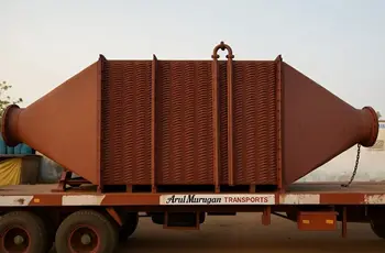
An air cooler header box is a critical pressure-retaining component in an air-cooled heat exchanger (ACHE) — also known as an air fin cooler or fin fan cooler. It is the enclosed chamber mounted at each end of the finned tube bundle that receives the incoming hot process fluid, distributes it uniformly across all cooling tubes, collects the cooled fluid at the outlet end, and returns it to the process.
Every air-cooled heat exchanger has at least two header boxes — one at each end of the tube bundle. In multi-pass designs, the header box is internally divided by pass partition plates, directing the fluid through multiple tube passes before it exits. The header box forms the pressure boundary for the tube-side fluid, and its integrity is critical to safe, leak-free operation of the entire unit.
💡 Why it matters: The header box is the single most maintenance-intensive component in an air-cooled heat exchanger. Its design — whether plug-type, cover plate, or manifold — directly determines how quickly and thoroughly the unit can be cleaned, inspected, and repaired during scheduled turnarounds. Choosing the right header box type for your service is as important as choosing the right tube material.
How Does an Air Cooler Header Box Work?
The air cooler header box is the entry and exit point for the process fluid in every air-cooled heat exchanger. Understanding its function within the complete heat transfer circuit is essential for correct operation and maintenance.
Fluid Entry
Hot process fluid enters the inlet header box through the inlet nozzle. The header's internal volume acts as a distribution plenum — slowing the fluid from nozzle velocity to an even, low-velocity distribution across all tube inlets simultaneously.
Tube-Side Flow
Fluid flows through the finned tubes from the inlet header to the outlet header. Heat conducts outward through the tube walls and fins into the surrounding airstream, cooling the fluid progressively along the tube length.
Forced Air Cooling
Fans mounted above or below the tube bundle force ambient air across the finned tube exterior at high velocity. The large fin surface area (15–20× bare tube area) ensures maximum convective heat transfer from tube to air — even with air's low heat transfer coefficient.
Cooled Fluid Exit
Cooled process fluid collects in the outlet header box and exits through the outlet nozzle back to the process. In multi-pass designs, the pass partition plate in the header box redirects fluid for additional tube passes before final exit.
Heat Transfer Mechanisms
Two complementary mechanisms drive heat transfer in every air cooler header box system:
- Conduction Through Tube Walls and Fins Heat moves from the hot process fluid inside the tube, through the tube wall metal, and into the fin base and fin body by thermal conduction. The thermal conductivity of the tube and fin material is therefore critical — aluminium fins on carbon steel tubes (the most common air cooler configuration) offer an excellent balance of conductivity, weight, and cost.
- Convection from Fin Surface to Air Heat dissipates from the fin surface into the forced airstream by convective heat transfer. The convective coefficient for air (h ≈ 30–60 W/m²·K) is far lower than for water — which is precisely why fins are essential: they compensate for air's poor heat transfer coefficient by multiplying the surface area available for convection by 15 to 20 times.
✅ Engineering rule: Air-cooled heat exchangers are most cost-effective when the air approach temperature (difference between hot process inlet temperature and ambient air temperature) is 20°C or greater. Below 20°C approach, the required fin tube area becomes very large and a water cooler may be more economical. Above 20°C approach, air cooling delivers compelling advantages in water savings, operating cost, and reliability.
Types of Air Cooler Header Boxes
The design of the header box is chosen based on operating pressure, fouling tendency, cleaning frequency, and budget. Four main types cover all industrial air-cooled heat exchanger applications.
1. Plug Type Header Box
The most widely used header box type in heavy industrial service. Individual threaded plugs — one opposite each tube end, one between each pair of tube ends — are screwed into the header face plate. Each plug can be removed independently to access a single tube for inspection, mechanical cleaning, or plugging without disturbing adjacent tubes or depressurising the entire unit.
- Best for: High-pressure refinery and petrochemical service, API 661 Class 1 applications, services requiring selective tube plugging during operation
- Pressure range: Up to 250 bar design pressure as standard
- Advantage: Individual tube access without full header disassembly; excellent pressure containment; preferred by API 661
- Maintenance: Plug removal requires plug wrench and re-torquing with thread sealant on reinstatement
- Materials: Carbon steel, stainless steel, chrome-moly for high-temperature hydrogen service
2. Cover Plate Header Box
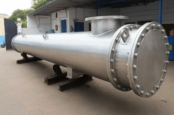
A single bolted plate covers the entire tube-end face of the header box. Removing the cover plate exposes all tube ends simultaneously, providing full access to every tube in the bundle for mechanical cleaning, inspection, and retubing. Fastest possible cleaning access — the entire tube face is revealed with a single bolted joint.
- Best for: Low-to-medium pressure services with frequent cleaning requirements, fouling-prone process fluids, food and pharma applications
- Pressure range: Typically up to 50 bar; heavy-duty versions to 100 bar
- Advantage: All tubes accessible simultaneously; fastest cleaning turnaround; simple gasket joint
- Maintenance: Full bundle access in one bolted joint removal — significantly faster than individual plug removal for large tube counts
3. Manifold (Welded) Header Box
A welded, non-removable header design where the header is permanently welded to the tube bundle. Used for clean, non-fouling services at lower pressures where tube access for mechanical cleaning is never required. Provides the most compact and leak-tight header construction.
- Best for: Clean gas cooling, power plant condensers, low-pressure utility services with chemically clean process fluids
- Advantage: No potential leak paths from plug or gasket joints; most compact design; lowest initial cost
- Limitation: No tube access for mechanical cleaning or selective plugging — tube-side fluid must be clean
4. Billet (Machined) Header Box
Header boxes machined from solid billet forgings rather than fabricated from welded plate. Used for ultra-high-pressure services — natural gas compression coolers, hydrogen plant coolers, and high-pressure injection coolers where design pressures exceed 250–300 bar.
- Best for: Natural gas compression aftercoolers, high-pressure hydrogen service, injection pump coolers, CNG station coolers
- Pressure range: 300 bar and above — the only viable header construction for these extremes
- Advantage: No welds in the header body — eliminates the primary failure mode in high-pressure service; maximum fatigue resistance
- Tube attachment: Tubes welded and strength-rolled into the billet header with full penetration welds; hydraulically tested per ASME/API 661
| Header Type | Max Pressure | Tube Access | Cleaning Speed | Relative Cost | Best Service |
|---|---|---|---|---|---|
| Plug Type | Up to 250 bar | Individual tubes via plugs | Medium — per-plug removal | Medium | Refinery, petrochemical, high-pressure |
| Cover Plate | Up to 100 bar | All tubes at once | Fast — single cover removal | Low–Medium | Fouling services, frequent cleaning |
| Manifold (Welded) | Up to 50 bar typical | None — chemical cleaning only | N/A | Lowest | Clean gas, utility, low-pressure |
| Billet (Machined) | 300 bar+ | Individual (plug or cover) | Medium | Highest | Gas compression, hydrogen, ultra-high pressure |
Unsure Which Header Box Type Suits Your Process?
Our API 661 / ASME certified engineers will review your fluid data, operating pressure, fouling history, and cleaning requirements — and recommend the optimal header box design, material, and configuration at no charge.
Get Free Engineering Advice →Key Components of an Air Cooler Header Box
Each component in the air cooler header box assembly plays a specific engineering role. Understanding them ensures correct specification, operation, and maintenance.
The internal chamber of the header box that receives fluid from the nozzle and distributes it uniformly to all tube inlets simultaneously. Proper manifold geometry eliminates maldistribution — the leading cause of hot spots, reduced efficiency, and premature tube failure in air coolers.
Flanged pipe connections welded into the header box wall through which process fluid enters and exits. Nozzle size and placement are engineered to maintain acceptable nozzle velocity (typically below 3 m/s for liquids) and minimize impingement erosion on tube ends or header walls.
Tubes are attached to the header tubesheet by strength rolling (expansion), seal welding, or strength welding — depending on service pressure, temperature, and fluid hazard level. API 661 specifies joint requirements per service class. This joint is the most critical structural element in the entire air cooler.
Internal dividing plate welded inside the header box to create multiple tube passes. In a 2-pass design, fluid enters through half the tubes, turns in the opposite header, and returns through the other half — doubling residence time and improving thermal efficiency for the same bundle length.
In plug-type headers, threaded plugs opposite each tube end provide individual tube access. In cover-plate headers, a single gasketed bolted plate reveals all tube ends. Plugs are specified per API 661 Table 2 — material, hex size, thread form, and sealant type are all code-defined for each service class.
Cover plate gaskets (spiral wound, ring joint, or flat sheet depending on pressure and temperature) and plug thread sealants maintain pressure integrity at all header box joints. API 661 mandates full hydrostatic testing of each header assembly at 1.5× design pressure before shipment.
Aluminium fins are helically wound, embedded, or extruded onto carbon steel or stainless tubes. Fin density, height, thickness, and bond quality directly determine the thermal performance of the air cooler. API 661 specifies minimum fin bond conductance requirements to prevent thermal performance degradation over time.
Variable-pitch axial fans (induced draft or forced draft) drive ambient air across the tube bundle. Fan pitch control — manual or automatic based on process outlet temperature — adjusts airflow and power consumption to match actual cooling demand, delivering up to 40% energy savings in variable-load service.
Vent and drain nozzles on each header box allow the tube side to be safely depressurised, drained, and vented before maintenance. Header boxes for hazardous or toxic services include double-block-and-bleed valve arrangements per process safety requirements.
Materials of Construction
Material selection for the air cooler header box is driven by the tube-side fluid chemistry, design temperature, design pressure, and corrosion allowance requirements. The header box is a pressure vessel — all materials must comply with ASME Section II and API 661 requirements.
| Material | Spec / Grade | Max Design Temp | Key Property | Typical Application |
|---|---|---|---|---|
| Carbon Steel | A516 Gr.70, A106 Gr.B | 425°C | Low cost, high strength, readily weldable | General refinery service, hydrocarbon cooling, steam |
| Stainless Steel 316L | A240 / A182 F316L | 870°C | Corrosion resistance, food/pharma safe, weldable | Corrosive process fluids, coastal environment, food & pharma |
| Chrome-Moly P11 | A387 Gr.11 / A182 F11 | 550°C | High-temperature strength, hydrogen service | Hydrotreater coolers, high-temperature refinery service |
| Chrome-Moly P22 | A387 Gr.22 / A182 F22 | 600°C | Superior high-temperature creep strength | High-temperature hydrogen, steam reformer coolers |
| Chrome-Moly P91 | A335 P91 / A182 F91 | 650°C | Highest creep strength for elevated temperature | Power plant steam coolers, ultra-high-temperature service |
| Duplex Stainless SS2205 | A240 / A182 F51 | 315°C | Superior chloride pitting resistance, double strength | Offshore, coastal environments, chloride-bearing process fluids |
| Aluminium Alloy | 6061-T6, 5083 | 150°C | Lightweight, excellent atmospheric corrosion resistance | Low-pressure gas cooling, offshore weight-critical installations |
| Alloy Steel (Low Temp) | A333 Gr.6, A352 LCB | −46°C min | Maintained toughness at sub-zero temperatures | Cryogenic gas processing, LNG facility coolers |
⚠ Critical rule: For any service containing wet H₂S (hydrogen sulphide), carbon steel header boxes must be specified with Post Weld Heat Treatment (PWHT) and tested per NACE MR0175 / ISO 15156 to prevent sulphide stress cracking (SSC) — a catastrophic failure mode that can occur within hours on non-compliant materials in sour service.
Design, Construction & Engineering Standards
Air cooler header boxes are engineered pressure vessels — every dimension, weld joint, nozzle, and plug must conform to internationally recognised codes. United Heat Exchangers designs and fabricates to the following standards:
The primary international standard for air-cooled heat exchangers. Specifies header box types, plug dimensions, tube-to-header joint requirements, fan and motor specifications, vibration limits, and full hydrostatic test requirements at 1.5× design pressure.
Governs pressure vessel design of the header box shell, cover plate, nozzle reinforcement, and weld joint efficiency. Division 2 design-by-analysis permits thinner walls at higher pressure, often reducing total weight by 20–30% for high-pressure billet headers.
Welding Procedure Specifications (WPS) and Procedure Qualification Records (PQR) for all header box weld joints. All United Heat Exchangers welders are qualified to ASME IX — the international benchmark for weld quality in pressure vessel fabrication.
Indian Standard (IS 2825) for unfired pressure vessels covers domestic project requirements. PED (Pressure Equipment Directive) and CE marking are required for export to the European Union — both are routinely handled by United Heat Exchangers for international projects.
Construction Quality Controls
- All header box shell plates and nozzle forgings inspected with Positive Material Identification (PMI) using XRF analysers at goods receipt
- All pressure welds — shell seams, nozzle welds, and tubesheet attachment welds — inspected by radiography (RT) or ultrasonic testing (UT) per ASME requirements
- Tube-to-tubesheet joints strength-rolled to API 661 minimum pull-out force, then seal-welded for hazardous or high-pressure services
- Full hydrostatic pressure test of each completed header box at 1.5× design pressure with third-party witness inspection available
- Complete dimensional inspection and ASME U-Stamp or National Board R-Stamp certification for all stamped units
Efficiency Factors: Fins, Flow, Fans & CO₂ Impact
The thermal and energy efficiency of an air cooler header box system depends on four interacting factors. Optimising all four simultaneously is the goal of every well-engineered air-cooled heat exchanger.
Fin density, height, and thickness control air-side thermal resistance — the dominant resistance in most air coolers.
Uniform fluid distribution across all tubes eliminates hot spots and maximises the effective heat transfer area of the bundle.
Variable-pitch axial fans match airflow to actual cooling demand — reducing fan power by up to 40% at partial load.
Air cooling eliminates cooling tower water losses (evaporation, blowdown) and the energy-intensive water treatment chemicals that generate CO₂.
Role of Fins in Efficiency
The fundamental challenge in air-cooled heat exchanger design is that air has a very low thermal conductivity and heat transfer coefficient compared to water. Fins solve this by multiplying the effective heat transfer surface area dramatically — without increasing the number of tubes or the size of the header box.
- Aluminium helical fins on carbon steel tubes — the industry standard. Fin density of 8–12 fins per inch (FPI) for most refinery and petrochemical service. 11 fins/inch for gas cooling where air-side pressure drop must be minimised.
- Embedded fins (extruded) — superior fin-to-tube bond conductance; preferred for high-temperature service above 200°C where interference-fit fins may relax and lose thermal contact.
- Solid aluminium fins — used for corrosive atmospheric environments (coastal, offshore) where galvanic corrosion at the fin-tube interface would degrade the fin bond on bimetallic (Al fin / CS tube) construction.
- Stainless steel fins on stainless tubes — used for full corrosion resistance in pharmaceutical, food, or aggressive coastal environments, accepting the lower thermal conductivity of SS vs aluminium.
Fan and Forced Air System
- Forced draft (fans below the bundle): More uniform air distribution across the tube face; easier fan maintenance; lower air inlet temperature to the fan (cooler air = higher fan efficiency). Most common configuration for refinery and petrochemical service.
- Induced draft (fans above the bundle): Hot discharge air rises naturally, reducing recirculation risk; better thermal performance in hot climates; fan operates in hot air stream — fan material must be rated for elevated temperature.
- Variable pitch fans with auto-control: Inlet guide vanes or variable pitch blades modulate airflow based on measured process outlet temperature. Energy savings of 30–50% over fixed-pitch fans across a typical seasonal operating cycle in climates with significant ambient temperature variation.
Sustainability note: Air-cooled heat exchangers eliminate the need for cooling water entirely — saving 1,500 to 3,000 litres per megawatt-hour of heat rejected compared to evaporative cooling towers. In water-scarce regions, this is not just an environmental preference — it is often a regulatory or site-permitting requirement that makes air cooling the only viable option.
Industrial Applications of Air Cooler Header Boxes
Air cooler header boxes are deployed wherever process fluids must be cooled reliably without cooling water — spanning the most demanding industrial environments in the world.

Food & Beverage
Hygienic air coolers for product cooling in food processing. 316L header boxes with sanitary nozzle finishes.

Oil & Gas Refining
Crude overhead condensers, product coolers, compressor aftercoolers. Plug headers in API 661 Class 1 service. NACE MR0175 compliance for sour crude.

Petrochemical
Reactor effluent coolers, distillation column overhead condensers, hot oil coolers. High-alloy plug headers for corrosive services.

Power Generation
Turbine lube oil coolers, generator hydrogen coolers, steam coolers. Chrome-moly headers for high-temperature steam service.

Natural Gas Processing
Gas compression aftercoolers and intercoolers, amine regenerator condensers, dehydration unit coolers. Billet headers for high-pressure compression service.

Offshore & Marine
Weight-optimised aluminium or duplex SS header boxes for offshore platforms. ABS/DNV-GL classified. Corrosion-resistant for salt spray environments.

Pharmaceutical
Precise temperature control in API synthesis and solvent recovery. 316L electropolished header boxes with sanitary nozzles and GMP documentation.

Fertilizer Plants
Ammonia synthesis loop coolers, urea process coolers, prilling tower air coolers. Corrosion-resistant headers for ammonia-containing process fluids.
Natural Gas Compression — Closer Look
Natural gas compression is one of the most demanding applications for air cooler header boxes. Compressor aftercoolers and intercoolers operate at pressures of 70–300 bar and temperatures of 120–180°C, with gas containing varying amounts of H₂S, CO₂, water, and heavy hydrocarbons. Key requirements include:
- Billet header construction for design pressures above 250 bar — eliminating the weld-related risk in high-pressure cyclic service
- NACE MR0175 / ISO 15156 material compliance for sour gas (H₂S-containing) service
- Pulsation analysis per API 618 for reciprocating compressor services — header box and nozzle design must avoid resonance with compressor discharge pulsations
- Low-temperature impact testing of header box steel to −46°C for high-altitude or cold-climate installations where ambient temperatures may fall below carbon steel's ductile-to-brittle transition
Key Features & Performance Characteristics
| Parameter | Typical Range | Governing Factor | Impact on Performance |
|---|---|---|---|
| Design pressure | 1 bar to 300 bar+ | Header type (plug, cover plate, billet) | Sets wall thickness, plug specification, and joint type |
| Design temperature | −46°C to 650°C | Material selection (CS, Cr-Mo, SS, low-temp alloy) | Determines creep allowance, PWHT requirement, and impact testing need |
| Fin density | 8–12 fins per inch (FPI) | Airside pressure drop allowance and fouling tendency | Higher FPI = more surface area = better performance but higher air pressure drop and fouling risk |
| Tube passes | 1 to 6 passes | Desired temperature approach and allowable pressure drop | More passes = higher tubeside velocity = better h value and less fouling |
| Fan coverage ratio | 40–50% of bundle face area per fan | Fan diameter and bundle bay width | Higher coverage = more uniform airflow distribution across tube bundle face |
| Airside approach temperature | 15–40°C (ambient to process inlet) | Location ambient temperature and process requirements | Minimum approach determines required fin tube area — lower approach = much larger (and more expensive) air cooler |
| Corrosion allowance | 1.5–6.0 mm | Fluid corrosivity and expected service life | Directly adds to header box wall thickness — higher CA = heavier, costlier header but longer inspection interval |
| Heat transfer area | 50–10,000 m² per unit | Heat duty, approach temperature, and fin geometry | Larger area = higher capital cost but lower fan power requirement and more capacity margin |
Plug Header vs Cover Plate Header: Detailed Comparison
The choice between plug-type and cover plate header boxes is the most common specification decision in air-cooled heat exchanger design. Here is a direct comparison across every relevant engineering and operational factor.
| Factor | Plug Type Header | Cover Plate Header |
|---|---|---|
| Maximum design pressure | Up to 250 bar (standard plug); higher with special plugs | Typically up to 50 bar; heavy-duty to 100 bar |
| Tube access method | Individual plugs removed one at a time — selective access | Single bolted cover reveals ALL tube ends simultaneously |
| Cleaning time (large bundle) | Longer — each plug must be individually removed and reinstated | Faster — single cover removal exposes complete tube face |
| Selective tube plugging | Yes — a leaking tube can be plugged while others remain in service | No — cover removal depressurises entire header |
| Leak potential | Multiple plug joints — each is a potential leak path requiring periodic re-torquing | Single peripheral gasket — one joint to maintain |
| API 661 class | Preferred for Class 1 (high-pressure and hazardous service) | Standard for Class 2 (lower pressure, general service) |
| Initial cost | Higher (machined plug holes, threaded inserts, individual plugs) | Lower (simpler fabrication, single bolted cover) |
| Maintenance cost (lifetime) | Higher if frequent full-bundle cleaning is required | Lower for fouling services requiring regular full-bundle cleaning |
| Best for | High-pressure refinery, petrochemical, sour gas, and hydrogen service | Medium-pressure fouling services, food, pharma, frequent-cleaning duties |
Need an Air Cooler Header Box for Your Plant?
United Heat Exchangers manufactures API 661 & ASME certified air cooler header boxes in plug type, cover plate, manifold, and billet configurations — for all industries and all process conditions. Engineering review & quote within 48 hours.
Request Your Free Quote →Maintenance & Inspection Guide
A disciplined maintenance programme keeps the air cooler header box performing at or near its design U-value throughout its service life and prevents the unplanned shutdowns that cost far more than scheduled maintenance.
📅 Routine Operational Monitoring (Weekly)
- Record inlet and outlet fluid temperatures — compare against the commissioning data sheet baseline; declining outlet temperature (rising ΔT loss) signals fouling
- Measure fan motor current draw — increasing current at constant pitch setting indicates fin fouling (higher airside pressure drop) or mechanical bearing wear
- Visually inspect all plug faces and cover plate gasket edges for signs of fluid weeping or incipient leaks
- Inspect fan blades for erosion, tip damage, or ice accumulation in cold climates; check fan pitch setting against control setpoint
- Monitor ambient air temperature and compare with design basis — high ambient periods require maximum fan operation and may necessitate supplemental cooling
📅 Annual Shutdown Inspection Checklist
- Remove all header box plugs (plug type) or the full cover plate and visually inspect every tube end for fouling, pitting, erosion, or corrosion
- Mechanically clean all accessible tube interiors using rotary brushes or high-pressure water lancing to remove scale and deposit
- Clean fin surfaces with low-pressure air blowing or gentle water washing — high-pressure washing damages fin tips and degrades thermal performance
- Perform eddy current testing (ECT) on a 10–20% representative sample of tubes; 100% ECT if previous inspection found wall thinning above threshold
- Hydrostatically pressure test each header box at 1.5× design pressure; investigate and repair any weep or pressure decay
- Replace all plug thread sealant (plug type) or full peripheral gasket set (cover plate type) — never reinstall a used gasket
- Inspect and re-torque all tube-to-header joint roller expansions at accessible tube ends; weld-inspect seal welds where specified
- Check fan blade pitch setting, fan blade leading edge condition, and gearbox or motor coupling condition; replace lubricants per manufacturer schedule
Fin Fouling & Cleaning Guide
| Fouling Type | Cleaning Method | Frequency | Prevention |
|---|---|---|---|
| Dust & particulate | Low-pressure compressed air blowing (max 3 bar); dry brush on delicate fins | Monthly to quarterly depending on environment | Install fin guards / debris screens on air inlet side |
| Biological growth (algae, pollen) | Low-pressure water wash with mild biodegradable detergent; avoid high-pressure water on fins | Quarterly to semi-annually | Site layout to minimise vegetation proximity; biocide air treatment in severe cases |
| Oil mist / hydrocarbon film | Alkaline degreaser spray (low pressure); soft brush agitation; rinse with water | Semi-annually or per inspection finding | Locate air cooler upwind of all hydrocarbon emission sources |
| Salt crystallisation (coastal) | Fresh water wash at low pressure to dissolve and flush salt crystals; repeat until conductivity of runoff equals fresh water | Monthly for coastal sites within 1 km of sea | Aluminium fin coating; duplex SS or solid aluminium fins for severe marine locations |
| Process fluid leak onto fins | Identify and fix tube-to-header leak first; then solvent clean contaminated fin area; replace damaged fin sections | Immediately on detection | Inspect plug and gasket joints monthly; maintain ECT inspection programme to catch tube leaks early |
Frequently Asked Questions — Air Cooler Header Boxes
1. What is an air cooler header box?
An air cooler header box is a pressure vessel component in an air-cooled heat exchanger that receives hot process fluid through its inlet nozzle, distributes it uniformly across all cooling tubes simultaneously, and collects the cooled fluid at the outlet end. It forms the pressure boundary for the tube-side fluid and provides maintenance access to the tube bundle interior.
2. How does an air cooler header box work?
Hot process fluid enters the inlet header box through the inlet nozzle. The header distributes it equally across all tube inlets. Fluid flows through finned tubes while fans force ambient air over the tube exterior, removing heat by convection. Cooled fluid collects in the outlet header box and exits through the outlet nozzle. In multi-pass designs, a pass partition plate inside the header redirects fluid for additional passes to achieve the required outlet temperature.
3. What is the difference between a plug header and a cover plate header?
A plug header has individual threaded plugs opposite each tube end, allowing one tube to be accessed, cleaned, or plugged at a time — ideal for high-pressure refinery service (up to 250 bar). A cover plate header has a single gasketed bolted plate that reveals all tube ends simultaneously — faster for full-bundle cleaning in lower-pressure fouling services (up to 100 bar).
4. What materials are used in air cooler header boxes?
Carbon steel (A516 Gr.70) is the standard material for general hydrocarbon service. Chrome-moly alloys (P11, P22, P91) are used for high-temperature or hydrogen services. Stainless steel 316L is specified for corrosive or sanitary applications. Duplex stainless is used in offshore and chloride environments. Aluminium alloys are used in low-pressure, weight-critical offshore applications. All materials comply with ASME Section II and API 661 material requirements.
5. What industries use air cooler header boxes?
Air cooler header boxes are used in oil and gas refining, petrochemical processing, natural gas compression, power generation, fertilizer manufacturing, pharmaceutical production, food processing, and offshore platforms — anywhere process fluids require reliable cooling without the need for cooling water.
6. How do fins improve air cooler efficiency?
Aluminium fins wound on the outside of the tubes increase the effective heat transfer surface area by 15 to 20 times compared to bare tubes. This compensates for air's inherently low heat transfer coefficient (approximately 30–60 W/m²·K compared to 2,000–10,000 W/m²·K for water), making air-cooled heat exchangers thermally viable for large industrial heat loads without requiring impractically large numbers of bare tubes.
7. How often should air cooler header boxes be inspected?
Routine operational monitoring (temperature, fan current, visual leak check) should be performed weekly during operation. Full header inspection — plug removal or cover plate removal, tube end inspection, mechanical tube cleaning, and hydrostatic pressure testing — is typically performed annually or aligned with major process turnarounds every 3–5 years. Fin surface cleaning should be carried out quarterly in clean environments and monthly in dusty, coastal, or hydrocarbon-contaminated locations.
8. Can United Heat Exchangers customise air cooler header boxes?
Yes. Every air cooler header box manufactured by United Heat Exchangers is custom-engineered to your specific process conditions — fluid type, flow rate, temperatures, design pressure, material, API 661 class, fouling service requirements, and code compliance. We provide free preliminary design review and budgetary pricing within 48 hours of receiving your process data sheet.
Why Choose United Heat Exchangers for Your Air Cooler Header Box?
United Heat Exchangers Pvt. Ltd is a leading Indian manufacturer of air-cooled heat exchangers and air cooler header boxes, with over 35 years of dedicated experience serving clients across refining, petrochemical, power, gas processing, offshore, and industrial manufacturing sectors.
Every air cooler header box is designed, fabricated, inspected, and tested per API 661 and ASME Section VIII. We hold current ASME U-Stamp and R-Stamp authorisations. All units are hydrostatically tested at 1.5× design pressure before shipment.
Full air cooler thermal and mechanical design using HTRI Xace software — the industry gold standard for air-cooled heat exchanger rating and design. Designs are optimised simultaneously for U-value, fan power, fin geometry, pressure drop, and vibration compliance.
All header box pressure parts supplied with EN 10204 3.1 or 3.2 mill certificates. Full PMI testing on all alloy components at goods receipt and post-fabrication. Complete material documentation package for every unit supplied.
All header box pressure welds inspected by RT, UT, MPT, or DPT per ASME requirements. Tube-to-header joints strength-tested to API 661 pull-out requirements. Third-party inspection and expediting fully supported for major projects.
Our air cooler header boxes eliminate cooling water dependency — saving 1,500–3,000 litres per megawatt-hour of heat rejected vs evaporative cooling towers. Variable-pitch fan designs reduce power consumption by up to 40% vs fixed-pitch alternatives.
Free preliminary thermal design, header box type recommendation, material specification, and budgetary pricing within 48 hours of receiving your process data sheet. Our in-house engineering team handles all technical queries directly — no outsourcing.
- ISO 9001:2015 certified quality management system covering all engineering, procurement, fabrication, inspection, and testing activities
- Global export compliance — PED/CE marking, IS 2825, and country-specific code compliance for international project delivery
- Lifetime after-sales support — OEM spare parts (plugs, gaskets, fan blades, tube bundles), on-site inspection assistance, and 24/7 emergency technical hotline
- Custom plug, cover plate, manifold, and billet header designs for any process fluid, pressure, temperature, material, or code requirement
- Marine and offshore classification — ABS, DNV-GL, Lloyd's Register, and BV design and fabrication certification available for offshore and shipboard installations
Ready to Specify Your Air Cooler Header Box?
Share your process data — fluid type, flow rate, inlet and outlet temperatures, design pressure, and site location — and our engineering team will deliver a complete header box type recommendation, material specification, and budgetary quote within 48 hours. No obligation. Completely free.
Request My Free Quote →Related Products: Air Cooled Heat Exchanger | Air Fin Cooler | Finned Tube Heat Exchanger | Air Cooled Condenser | Compressor Cooler | After Cooler | Intercooler
Author: Senthil Kumar, Technical Director — United Heat Exchangers Pvt. Ltd | Published: March 2026 | Category: Heat Exchanger | Tags: Air Cooler Header Box, Plug Header, Cover Plate Header, API 661, ACHE, Air Fin Cooler