Author: Senthil Kumar, Technical Director | Updated: May 2026
Table of Contents
- What Is a Compressor Cooler?
- How It Works
- Key Components and Materials
- Types of Compressor Coolers
- Configurations and Geometry
- Design Specifications and Standards
- Industries and Applications
- Air Cooled vs Water Cooled Compressor Cooler
- Energy Efficiency and Controls
- Maintenance Guide
- Why United Heat Exchangers
- Delivery and What's Included
- Frequently Asked Questions
- Request a Free Quote

What Is a Compressor Cooler?
A compressor cooler is a heat exchanger that removes compression heat from a gas stream — either between compression stages (inter-stage cooling), after the final stage (after-cooling), or from the compressor lube oil circuit (oil cooling). Every act of compression raises gas temperature; that heat must be extracted before the gas enters the next stage, the downstream process, or the pipeline.
Without adequate cooling, compressor efficiency falls, discharge temperatures exceed mechanical limits, gas density drops, and downstream equipment — valves, seals, pipelines — operates outside design conditions. A well-sized, correctly installed compressor cooler is not an accessory to the compression system. It is a core part of it.
As a leading compressor cooler manufacturer and supplier in India, United Heat Exchangers designs and fabricates air-cooled and water-cooled compressor coolers for natural gas, process gas, air compression, refrigeration, and industrial gas service — to API 661, ASME Section VIII, and TEMA standards, with a written thermal performance guarantee on every unit.
How a Compressor Cooler Works
The working principle is straightforward. Compression raises both pressure and temperature. The cooler extracts the heat of compression from the gas before it re-enters the next stage, enters the process, or is metered into the pipeline — recovering gas density and protecting all downstream equipment.
Hot Gas Enters
Compressed gas at elevated temperature and pressure leaves the compressor stage and enters the cooler's inlet nozzle, distributing into the tube bundle or shell side.
Cooling Medium Flows
Ambient air (axial fans) or cooling water circulates across or through the opposite side of the heat transfer surface — maintaining a continuous temperature driving force.
Heat Transfers
Thermal energy moves from the hot gas through the tube wall — or fin surface in air-cooled units — into the cooling medium. Gas temperature drops progressively across the bundle length.
Condensate Separates
As gas cools, water vapour and heavy hydrocarbon fractions condense out. The cooler outlet connects to a knock-out drum or separator that removes the liquid before the gas proceeds.
Cooled Gas Exits
Gas leaves the cooler at the target outlet temperature — denser, drier, and ready for the next compression stage or downstream delivery point.
Controls Maintain Setpoint
VFD fans or cooling water flow control continuously hold gas outlet temperature at the setpoint across seasonal ambient variation and changing compressor load.
💡 Outlet temperature governs everything downstream. Each degree above the target outlet temperature reduces gas density entering the next stage — increasing the power required to compress the same mass flow. Over-temperature also drives seal degradation, valve wear, and moisture carryover. Sizing a compressor cooler to the worst-case summer ambient is not conservatism — it is the minimum standard of correct design.
Key Components and Materials
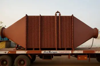
Finned Tube Bundle (Air-Cooled)
The primary heat transfer surface in air-cooled compressor coolers. Gas or lube oil passes through the tubes; aluminium fins bonded to the outside multiply the air-side surface area. Fin type — extruded, embedded L-foot, or tension-wound — is selected for the combination of operating temperature, gas composition, and atmospheric corrosivity at the installation site.
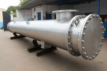
Shell and Tube Bundle (Water-Cooled)
Gas or oil travels via straight tubes held between fixed or floating tubesheets in water-cooled compressor coolers. Cooling water flows through the shell side in a counterflow or cross-counterflow arrangement. TEMA B or TEMA R construction to match the gas service hazard class. Fixed tubesheet, U-tube, or floating-head configuration depending on differential thermal expansion requirements.
Headers and Nozzles
Plug-type or cover-plate headers distribute gas evenly across all tube rows on entry and collect it at exit. Header nozzles are sized to limit gas-side pressure drop — every bar of unnecessary pressure drop across the cooler is work wasted by the compressor. Drain and vent connections positioned to clear condensate and non-condensable gas accumulations during start-up and shutdown.
Axial Fans and Drive Assemblies
Large-diameter, low-RPM axial fans move the air volume required to achieve the target gas outlet temperature at the maximum design ambient. Aluminium or FRP fan blades on variable-pitch hubs allow airflow trimming at part-load. VFD-equipped motors allow continuous speed modulation — the primary lever for managing energy consumption and outlet temperature simultaneously.
Plenum Chamber
The transition section between the fan ring and the tube bundle face. A well-proportioned plenum produces a uniform velocity profile across the full bundle width — eliminating areas of reduced airflow that would otherwise create localised hot zones and degrade overall thermal performance below the rated design value.
Structural Frame
Hot-dip galvanised carbon steel structure engineered to applicable wind load, seismic, dead load, and bundle weight design codes. Where the installation site has an aggressive corrosion category — coastal, offshore, or chemical plant atmospheres — all structural members, grating, and fasteners are specified in stainless steel or given a C5-M coating system.
Knock-Out Drum (Where Required)
An integral or closely coupled knock-out drum collects liquid condensed from the gas stream during cooling. Correctly sized liquid-gas separation prevents liquid carryover into the downstream compressor stage or pipeline — a critical protection against liquid slugging and valve damage in reciprocating compressors.
Instrumentation and Controls
Gas-side inlet and outlet temperature transmitters, inlet pressure indication, and differential pressure measurement across the bundle. Fan vibration monitoring and motor temperature alarms. VFD control logic programmed to hold the target gas outlet temperature using ambient dry-bulb compensation. All instrumentation rated to the hazardous-area classification of the compressor installation.
Types of Compressor Coolers
A compression system has three main cooling functions, each with unique operating circumstances, the effects of subpar performance, and design considerations.
⇄ Inter-Stage Cooler
Between compression stages — cooling gas before recompressionPositioned between successive compression stages to reduce gas temperature before it enters the next stage. Cooler gas is denser — the compressor moves the same molar flow rate with less volumetric throughput, directly lowering stage power consumption.
- Directly reduces compressor power — cooler inlet gas to each stage lowers the specific work of compression
- Removes condensate between stages — water and heavy hydrocarbons drop out before the next stage, protecting valves and cylinders
- Gas outlet temperature typically targeted at 40°C–55°C above site ambient
- Pressure drop budget is tight — each kPa lost is energy wasted by the upstream stage
- Standard for multi-stage centrifugal, axial, and reciprocating compressors in gas processing and petrochemical service
⇩ After-Cooler
After the final compression stage — cooling gas for delivery or storageCools compressed gas leaving the final stage to the temperature required by the downstream system — pipeline specification, process feed requirement, or storage vessel temperature rating. Final condensate removal occurs at the after-cooler outlet separator.
- Pipeline and process temperature compliance — delivers gas at or below the specified maximum delivery temperature
- Final liquid removal — last opportunity to separate condensate before the gas enters the pipeline or process
- Often the largest single cooler duty in the compression train
- Outlet temperature specification is typically 10°C–15°C above ambient or a fixed maximum (e.g. 50°C for most gas transmission codes)
- Preferred for natural gas compression, instrument air systems, industrial gas packaging, and CNG stations
🛢 Lube Oil Cooler
Cooling compressor lube oil — protecting bearings and sealsRemoves heat from the compressor lubrication circuit to maintain bearing oil temperature within the viscosity range required for full hydrodynamic film formation. Oil that is too hot loses viscosity and bearing load capacity; oil that is too cold increases startup resistance and power draw.
- Bearing protection — oil temperature control is the primary defence against bearing wear and failure
- Seal system compatibility — dry gas seal systems and wet seal systems both have oil temperature limits that the cooler must maintain
- Shell and tube construction is most common — compact, cleanable, and tolerant of the oil fouling factor
- Oil inlet temperature typically 60°C–80°C; outlet target 40°C–55°C
- Thermostatic bypass valve maintains minimum oil temperature during cold start — prevents condensation contamination of the oil circuit
⚡ Gas Cooler / Trim Cooler
Temperature adjustment for process or pipeline specification complianceNot all compressor cooler duties are stage-based. Gas coolers and trim coolers adjust the temperature of a gas stream at a specific point in the process — brought down to a reaction temperature, a dew point target, or a downstream equipment inlet limit.
- Dew point management — cooling gas to its hydrocarbon dew point to recover liquids before pipeline entry
- Reactor feed conditioning — trimming feed gas temperature to the catalyst bed inlet specification
- Variable duty — often driven by changing feed compositions or seasonal ambient swings
- VFD fan control or three-way water valve essential for maintaining outlet temperature at a tight setpoint
- Common in natural gas processing, hydrogen plants, and synthesis gas compression trains
💡 Match the cooler type to the compression duty precisely. Inter-stage and after-coolers look similar on a drawing — but their pressure drop budgets, outlet temperature targets, and condensate handling requirements differ significantly. United Heat Exchangers engineers each cooler to the specific stage conditions, not to a generic cooler standard.
Configurations and Geometry
Horizontal Flat-Bed Air-Cooled
Finned tube bundles oriented horizontally above forced-draft or induced-draft axial fans. The most common configuration for compressor after-coolers and inter-stage coolers in refinery, gas plant, and pipeline compressor station service. Straightforward to expand by adding bays as compression capacity grows.
Vertical Discharge Air-Cooled
Fans mounted below with airflow directed vertically upward through the bundle. Low structural height — suited to plot-constrained compressor station layouts where overhead clearance is limited but ground-level footprint is available. Preferred configuration for skid-mounted compressor packages.
Shell and Tube — Fixed Tubesheet
Gas or oil through the tubes; cooling water on the shell side. Fixed tubesheet construction is the simplest and lowest-cost arrangement — suited to services where the temperature difference between gas and cooling water does not generate differential thermal expansion beyond the tubesheet's elastic limit.
Shell and Tube — Floating Head
One tubesheet is free to move axially within the shell — accommodating the differential thermal expansion between tube bundle and shell when gas temperatures are high or cooling water temperature varies widely. Required for high-temperature gas cooler duties and for services where the bundle must be fully removable for inspection and cleaning.
Shell and Tube — U-Tube
Tubes bent into a U-shape — both ends terminate at the same tubesheet, and the bundle withdraws from one end. Inherently handles differential thermal expansion. Lower capital cost than a floating head for equivalent thermal duty. The preferred configuration for compressor lube oil coolers in clean oil services where the shell side is accessible for inspection.
Multi-Bay Skid-Mounted Package
Multiple cooler bays — inter-stage, after-cooler, and oil cooler — mounted on a common structural skid with shared piping headers, control panel, and instrument junction boxes. Factory-assembled, tested, and shipped as a single lift to site. Reduces field installation time significantly and allows full performance testing at the manufacturer's shop before dispatch.
Design Specifications and Standards
Every compressor cooler is custom-engineered to the stage conditions, gas composition, site ambient data, and plot constraints of the specific installation — thermally rated with HTRI Xchanger Suite and designed to the governing standard for the service class.
| Specification | Range / Options |
|---|---|
| Cooler Type | Inter-stage cooler, after-cooler, lube oil cooler, gas trim cooler |
| Cooling Medium | Ambient air (air-cooled, API 661) or cooling water (shell & tube, TEMA B / TEMA R) |
| Draft Arrangement (Air-Cooled) | Induced draft (fans above) or forced draft (fans below) |
| Design Pressure — Gas Side | Full vacuum to 500 bar; high-pressure gas service available |
| Design Temperature | -50°C to 600°C (-58°F to 1,112°F) |
| Gas Side Tube Material | Carbon steel, 304/316L stainless, duplex 2205, Alloy 825, Alloy 625, titanium Gr.2 |
| Fin Type (Air-Cooled) | Extruded, embedded L-foot, KLM knurled, tension-wound — aluminium or stainless fins |
| Fin Density | 7 to 11 fins per inch (fpi); custom density for fouling or high-viscosity gas services |
| TEMA Shell Type | E, F, G, H, J, X — selected for pressure drop and thermal efficiency requirements |
| Header / Bonnet Type | Plug-type, cover-plate, box header, channel with removable cover (TEMA types A, B, C, D, N) |
| Fan Diameter (Air-Cooled) | 4 ft to 20 ft (1.2 m to 6 m); low-speed large-diameter axial fans |
| Fan Drive | Direct-drive motor, V-belt, right-angle gearbox; VFD available on all configurations |
| Structural Coating | Hot-dip galvanised; epoxy/polyurethane topcoat; C5-M marine/offshore systems |
| Design Standard (Air-Cooled) | API 661, ASME BPVC Section VIII Div. 1 & 2, ASME Section IX, AISC structural |
| Design Standard (Shell & Tube) | TEMA B / TEMA R, ASME BPVC Section VIII Div. 1 & 2, ASME Section IX |
| Special Options | Integral knock-out drum, skid-mounted package, ATEX/IECEx motors, winterisation, acoustic enclosures, adiabatic pre-cooling |
Industries and Applications
Natural Gas Compression
Pipeline, gathering, and LNG feed gasOil & Gas Refining
Recycle gas, make-up hydrogen, and off-gas compressionPetrochemicals
Ethylene, propylene, and synthesis gas compressionIndustrial Air Compression
Instrument air, plant air, and process gas compressionFertilizer and Ammonia Plants
Synthesis gas and nitrogen compressionHydrogen and Syngas
Reformer gas, hydrogen recycle, and CO₂ compressionPower Generation
Gas turbine inlet, igcc, and steam injection systemsOffshore and Marine
Platform compression, gas lift, and export gasCompressor Coolers for Every Stage, Every Gas, Every Industry
Inter-stage, after-cooler, lube oil, and gas trim cooling — API 661 and ASME certified, HTRI rated, written thermal performance guarantee. Free quote in 48 hours.
Request My Free Quote →Air Cooled vs Water Cooled Compressor Cooler
The selection of cooling medium is not based on a general preference, but rather on site water supply, ambient conditions, maintenance resources, and lifespan cost. Here is an honest technical comparison.
| Criterion | Air-Cooled Compressor Cooler | Water-Cooled Compressor Cooler |
|---|---|---|
| Water Requirement | ✅ None — no cooling water circuit, no treatment system | ⚠ Continuous cooling water supply required; treatment, blowdown, and make-up system needed |
| Achievable Outlet Temperature | ⚠ Limited by ambient dry-bulb — typically 15°C–25°C above ambient | ✅ Approaches cooling water supply temperature — lower outlet temperatures achievable where cold water is available |
| Capital Cost | ⚠ Higher equipment cost — fans, motors, structural frame, larger footprint | ✅ Lower per-unit equipment cost — but total installed cost includes cooling tower and water circuit |
| Operating Cost | ✅ Fan power only — no water procurement, treatment chemicals, or tower losses | ⚠ Water make-up, chemical dosing, pump energy, tower fan power, and water disposal costs accumulate |
| Maintenance | Fin cleaning, fan vibration checks, bearing lubrication — predictable and straightforward | Water-side fouling, tube scaling, corrosion, and biological growth require ongoing water quality management |
| Fouling | Air-side dust managed by periodic fin cleaning | Water-side scaling and biological fouling degrade thermal performance continuously if water treatment lapses |
| Ambient Sensitivity | ⚠ Performance tracks dry-bulb temperature — hot summer days reduce cooling capacity | Tracks cooling water supply temperature — performance more stable across seasons |
| Plot Footprint | ⚠ Larger plot area for equivalent thermal duty | Compact exchanger body — but cooling tower adds overall site footprint |
| Remote/Arid Sites | No water supply required — ideal for pipeline compressor stations, desert, and remote sites | ⚠ Requires water source or trucked supply — impractical for many remote gas compression locations |
| Environmental Compliance | No cooling tower plume, no chemical waste, and no water outflow/td> | ⚠ Legionella risk management responsibilities, chemical disposal laws, and water discharge permits |
💡 The right answer depends on your site. Where cooling water is unavailable, restricted, or the lifecycle cost of a water system is prohibitive — air cooling is the engineering answer. Where the gas outlet temperature target is tight and cold water is reliably available, water-cooled shell-and-tube may be more compact and economical. United Heat Exchangers designs both types and recommends based on your actual site data — not on what is easiest to fabricate.
Energy Efficiency and Control Strategies
Fan power in air-cooled compressor coolers and pump power in water-cooled systems represent real, recurring operating cost. Designing the control strategy alongside the cooler — not as an afterthought — determines how much of that cost is recovered across the equipment's operating life.
Variable Frequency Drives (VFDs)
Fan shaft power scales with the cube of rotational speed. Reducing fan speed to 75% of full speed drops power consumption to roughly 42% of the full-speed value. VFDs continuously adjust fan speed to hold the gas outlet temperature setpoint — cutting fan energy during the mild ambient seasons that account for the majority of operating hours on most sites.
Outlet Temperature Control Logic
Rather than running fans at fixed speed, outlet temperature-based control adjusts fan speed in real time as ambient dry-bulb and gas inlet temperature change with load and season. This eliminates overcooling — which wastes fan energy and, in some gas services, risks dropping the gas below its hydrocarbon dew point inside the cooler.
Fan Staging for Multi-Bay Units
In multi-bay compressor cooler installations, staging control runs only the number of fan bays needed to achieve the target outlet temperature at the current ambient and heat load. Bay rotation equalises accumulated run-hours and bearing wear across all installed fan assemblies, extending mean time between maintenance interventions.
Variable-Pitch Fan Blades
Manually or automatically adjustable blade pitch hubs deliver the same airflow at a shallower blade angle during cooler ambient conditions — drawing less motor current for the same thermal throughput. A practical alternative to VFDs for compressor station installations with simpler control system requirements or where VFD installation is constrained by electrical area classification.
Minimum Temperature Protection
In cold climates, gas outlet temperature must stay above a minimum threshold to prevent moisture condensation and hydrate formation inside the cooler. Motorised louvers restrict airflow during cold ambient conditions to maintain the minimum acceptable outlet temperature — protecting the compressor system from hydrate plugging and condensate-induced corrosion in the downstream piping.
Adiabatic Pre-Cooling (High-Ambient Sites)
At peak summer ambient temperatures where air-cooled performance is constrained by dry-bulb temperature, evaporative pad or direct water injection pre-coolers lower the inlet air temperature before it reaches the fin surface. A targeted summer-peak measure that avoids the permanent capital cost of a water-cooled backup system while managing the most demanding ambient conditions of the year.
Maintenance Guide — Keeping Compressor Cooler Performance On-Spec
A compressor cooler that drifts off its thermal design point does not just consume more energy — it degrades compressor efficiency, raises discharge temperatures, increases condensate carryover risk, and can trigger compressor high-temperature trips that cost production. Scheduled maintenance prevents all of these outcomes at a fraction of the cost of recovering from them.
| Task | Frequency | What to Check / Do |
|---|---|---|
| Fin Surface Inspection | Monthly visual | Examine the air-inlet face of the bundle for dust accumulation, oil mist deposits, debris blockage, and bent or damaged fins — all of which reduce effective airflow through the bundle |
| Fin Cleaning | Quarterly or per inspection findings | Blow compressed air or apply a low-pressure fresh water wash from the air-outlet face toward the inlet. Never direct high-pressure water jets at aluminium fins — pressure above 3 bar risks mechanical fin damage and permanent reduction in heat transfer area |
| Gas Outlet Temperature Log | Continuous — trend weekly | Track gas outlet temperature minus ambient dry-bulb at the same fan speed and heat load. A widening gap between these two values over successive weeks is the earliest reliable indicator of fin fouling — act before it becomes a process constraint or compressor trip |
| Fan Vibration Monitoring | Monthly — continuous monitoring preferred | Confirm vibration switch setpoints are correctly programmed and active. Any abrupt rise in vibration amplitude at constant fan speed warrants immediate shutdown and inspection — it commonly signals progressive fan blade imbalance or early-stage bearing degradation before failure occurs |
| Bearing Lubrication | Per OEM schedule — typically every 3–6 months | Apply the manufacturer's specified lubricant in the specified quantity. Record in the CMMS against equipment tag. Both under-greasing and over-greasing damage bearings — fill quantity must match the OEM specification, not a general estimate |
| Motor Current and Temperature | Monthly log | Log motor current against the baseline value at the same fan speed setting. Current rising above the baseline at constant speed points to increased mechanical resistance in the drive train — investigate before the motor reaches a thermal trip condition |
| Gas-Side Pressure Drop Check | Quarterly | Measure differential pressure across the cooler gas side against the clean design value. Rising pressure drop at constant flow indicates internal fouling — carbon deposits, scale, or heavy liquid accumulation inside the tubes reducing flow area |
| Knock-Out Drum Level and Drain | Daily where condensate volumes are significant | Verify the knock-out drum level indicator is reading correctly and the automatic drain valve is functioning. Liquid accumulation above the high-level alarm set point risks liquid carryover into the downstream compressor stage — a leading cause of valve and cylinder damage in reciprocating compressors |
| VFD Inspection | 6-monthly | Inspect cabinet cooling fans, inlet filter condition, and all power and control terminal connections. Verify the VFD responds correctly across the full operating speed range from minimum to maximum. Log drive operating hours for bearing replacement planning |
| Structural and Coating Inspection | Annual | Examine structural members, grating, and bolted connections for coating deterioration and advancing corrosion. Address coating damage during the annual inspection — steel section loss from corrosion discovered at a five-year interval is always more expensive to repair than paint applied to a surface scratch discovered at one year |
💡 Track gas outlet temperature minus ambient — not outlet temperature alone. Gas outlet temperature rises naturally on hot days even with a perfectly clean cooler. The performance metric that reveals fouling is the difference between gas outlet temperature and ambient dry-bulb at the same fan speed and heat duty. If that gap increases progressively across successive quarterly readings, the fins are fouling and cleaning is already overdue.
Why United Heat Exchangers
Designing a compressor cooler that holds its gas outlet temperature on the hottest day your site records — without tripping the compressor on high-discharge-temperature — requires correct stage-by-stage thermal design, accurate ambient data application, and gas composition-matched material selection. United Heat Exchangers applies all three to every unit. It is our standard engineering practice, not an optional upgrade.
35+ Years of Compressor Cooler Manufacturing
Compressor coolers — air-cooled and shell-and-tube — have been part of our core product range for over three decades. Engineering lessons from delivered units across refinery, gas plant, and pipeline compressor station service are embedded in every design we issue.
HTRI Thermal Design — Written Guarantee
Every compressor cooler is thermally rated in HTRI Xchanger Suite at your site's maximum design dry-bulb temperature and worst-case gas inlet conditions. We issue a written thermal performance guarantee — not a datasheet estimate. Your cooler holds its outlet temperature on the hottest day of the year.
API 661 and ASME U-Stamp Certified
Air-cooled compressor coolers are designed to API 661 and ASME BPVC Section VIII. Shell-and-tube units are designed to TEMA B / TEMA R and ASME Section VIII. U-Stamp Manufacturer's Data Report issued with every ASME-stamped unit — independently audited, current certifications.
Stage-Specific Thermal Design
We design to your specific stage inlet conditions — temperature, pressure, gas composition, mass flow, and required outlet temperature — not to a generic compression service assumption. Each inter-stage and after-cooler in a multi-stage train is individually rated to its actual duty.
Complete Package Supply
Air-cooled bundles, shell-and-tube exchangers, lube oil coolers, knock-out drums, structural frames, fans, motors, VFDs, instrumentation, and all documentation — engineered, fabricated, and tested under one quality system and one supply contract. Skid-mounted compressor cooler packages available.
Replacement Bundle Capability
Replacement finned tube bundle sections and shell-and-tube core replacements manufactured to the original nozzle layout, bay dimensions, and tube count of existing units — when the structural frame, fans, or shell are still serviceable but the heat transfer core has reached end of thermal life.
Delivery and What's Included
What's Included with Every Compressor Cooler Order
- Written HTRI thermal performance guarantee — rated at your site's maximum ambient dry-bulb and specified stage inlet conditions, issued before fabrication and confirmed at delivery
- API 661 compliance documentation — data sheet, vendor data package, and all API 661 required documentation for air-cooled units in petroleum and petrochemical service
- TEMA data sheet — for all shell-and-tube compressor coolers, completed to the applicable TEMA class
- ASME U-Stamp Manufacturer's Data Report (MDR) — for all pressure-containing components, signed by the Authorised Inspector
- Material certifications (MTRs) — mill test reports for all tubes, headers, shells, and nozzles; traceable to heat and lot number
- Hydrostatic test certificate — gas-side pressure tested to 1.5× design pressure; third-party witness available on request
- Fan performance certification — airflow, static pressure, and power draw confirmed against manufacturer's certified test data
- Structural design certificate — structural calculations to applicable wind, seismic, dead load, and bundle weight standards
- Coating inspection records — DFT measurements and holiday test records for all coated surfaces
- Operation and maintenance manual — fin cleaning procedure, VFD settings guide, bearing lubrication schedule, knock-out drum drain procedure, seasonal checklist, and spare parts list
- Lifetime technical support — thermal re-rating for changed stage conditions, fan upgrade, bundle replacement, and performance troubleshooting throughout each unit's service life
Get a Free Compressor Cooler Quote in 48 Hours
Share your stage conditions (gas composition, inlet temperature and pressure, required outlet temperature, mass flow), site ambient dry-bulb, site elevation, noise limits, and applicable codes. Our engineering team sizes the right cooler configuration and delivers a technical proposal within 48 hours.
Request My Free Quote →Frequently Asked Questions
What is a compressor cooler?
A compressor cooler is a heat exchanger that removes compression heat from a gas stream — either between compression stages (inter-stage cooler), after the final stage (after-cooler), or from the compressor lube oil circuit (oil cooler). Its function is to restore gas density and temperature to the required level before the next stage, the downstream process, or the delivery pipeline.
What is the difference between an inter-stage cooler and an after-cooler?
An inter-stage cooler sits between two compression stages and cools the gas before it enters the next stage — directly reducing the power required for subsequent compression and removing condensate that would otherwise carry into the next stage. An after-cooler sits downstream of the final compression stage and cools the gas to the temperature required by the downstream system — pipeline specification, process equipment inlet limit, or storage vessel rating. Both use the same heat transfer principles; the difference is their position in the compression train and the consequences of failure.
Why is gas outlet temperature important in compressor cooling?
Each degree above the target outlet temperature reduces the density of gas entering the next stage — requiring more volumetric throughput to move the same mass flow, which increases compressor shaft power. Excessive outlet temperature also drives accelerated seal and valve wear, raises the risk of hydrocarbon condensation downstream of the target point, and can trigger compressor high-temperature protection trips. Maintaining the output temperature at the design setpoint is not just a thermal standard, but also an operational and reliability requirement.
How do I select between air-cooled and water-cooled for my compressor cooler?
The primary deciding factors are water availability at the site, the required gas outlet temperature, and the lifecycle cost of each option. Air-cooled units require no water and suit remote compressor stations, arid sites, and offshore platforms — but their outlet temperature is constrained by ambient dry-bulb temperature. Water-cooled shell-and-tube units can achieve lower outlet temperatures where cold water is available, but carry the full lifecycle cost of a cooling water circuit, water treatment system, and associated permitting obligations. United Heat Exchangers performs a site-specific comparison for every enquiry where the choice is not immediately obvious.
What causes a compressor cooler to lose thermal performance?
For air-cooled units, the most common cause is progressive fin fouling from dust, oil mist, and airborne contaminants reducing the effective airflow through the bundle. For water-cooled shell-and-tube units, tube-side fouling from scale, biological growth, or process deposits is the leading cause. Both manifest as a widening gap between gas outlet temperature and the design approach at constant fan speed and heat load. The degradation is gradual and easily missed without a trending monitoring programme — which is why approach ΔT tracking is more reliable than monitoring outlet temperature alone.
Can you supply a complete skid-mounted compressor cooler package?
Yes. United Heat Exchangers designs and supplies multi-stage compressor cooler trains — inter-stage coolers, after-cooler, and lube oil cooler — mounted on a common structural skid with shared piping, control panel, instrumentation junction boxes, and all documentation. The complete skid is assembled and pressure-tested at our Coimbatore facility before dispatch, substantially reducing field installation time and minimising site commissioning risk.
What maintenance does a compressor cooler require?
Air-cooled compressor coolers require periodic fin cleaning, fan vibration monitoring, bearing lubrication, and VFD inspection. Water-cooled shell-and-tube coolers require water-side tube bundle inspection, cleaning, and water quality management. Both types benefit from continuous gas outlet temperature trending against ambient dry-bulb — this is the most reliable early warning of cooling performance degradation before it becomes a compressor reliability issue.
What is the delivery time for a compressor cooler from United Heat Exchangers?
Single-unit standard air-cooled or shell-and-tube compressor coolers in carbon steel or stainless steel deliver in 5–8 weeks from order confirmation and approved drawings. Multi-stage cooler trains, alloy material units, high-pressure services, and skid-mounted packages deliver in 10–18 weeks. Expedited schedules for compressor turnaround and emergency replacement are available on request.
Author: Senthil Kumar, Technical Director — United Heat Exchangers Pvt. Ltd. | Last Updated: May 2026