Air Cooled Condenser
Author: Senthil Kumar, Technical Director | Updated: May 2026
Table of Contents
- What Is an Air Cooled Condenser?
- How It Works
- Key Components and Materials
- Forced Draft vs Induced Draft
- Configurations and Geometry
- Design Specifications and Standards
- Industries and Applications
- Air Cooled vs Water Cooled Condenser
- Energy Efficiency and Controls
- Maintenance Guide
- Why United Heat Exchangers
- Delivery and What's Included
- Frequently Asked Questions
- Request a Free Quote
What Is an Air Cooled Condenser?
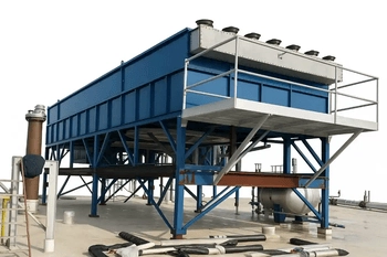
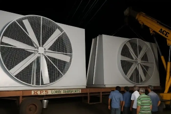
An air cooled condenser (ACC) is a heat exchanger that condenses hot vapour — steam, refrigerant, or process vapour — back into liquid using ambient air as the sole cooling medium. No cooling water. No cooling tower. No water treatment system.
Hot vapour enters finned tube bundles. Motor-driven axial fans move a large volume of ambient air across the fin surfaces. Heat transfers from the vapour through the tube wall and fins into the air — and the vapour condenses into liquid, ready to return to the process or cycle.
As a leading air cooled condenser manufacturer and supplier in India, United Heat Exchangers designs and fabricates forced draft and induced draft ACCs for power generation, petrochemicals, oil and gas, refrigeration, and HVAC — to API 661 and ASME Section VIII standards, with a written thermal performance guarantee on every unit.
How an Air Cooled Condenser Works
The working principle is simple. The engineering challenge is in sizing the fin geometry, air flow, and fan arrangement to maintain stable condensing pressure at the worst-case ambient conditions the site will ever experience.
Vapour Enters Headers
Hot vapour — steam, refrigerant, or process vapour — enters the inlet header and distributes evenly into the finned tube rows.
Fans Move Air
Large-diameter axial fans push or pull ambient air across the finned tube surface — the fin geometry multiplies the effective heat transfer area many times over bare tube.
Heat Transfers Through Fins
Thermal energy moves from the hot vapour, through the tube wall and fin surface, and into the passing air stream — driven by the temperature differential between vapour and ambient air.
Vapour Condenses
As heat leaves, the vapour changes phase from gas to liquid inside the tubes — at near-constant temperature and pressure. A sub-cooling zone ensures stable liquid delivery to downstream equipment.
Condensate Exits
Liquid condensate collects at the outlet header and drains to a receiver, hotwell, or process return line — completing the cycle.
Controls Maintain Stability
VFD fan speed, louvers, and staged fan operation continuously adjust air flow to maintain the target condensing pressure across seasonal ambient variations.
💡 The approach temperature drives everything. The condensing temperature minus the ambient dry-bulb temperature is the approach ΔT. A tighter approach means more fin area and more fan power. A wider approach means a smaller, cheaper unit that runs at a higher condensing pressure. Every ACC design balances three competing variables — capital expenditure, fan power consumption, and condensing pressure — and our proposals lay that balance out explicitly so clients can make an informed decision.
Key Components and Materials
Finned Tube Bundle
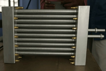
The heat transfer core. Tubes carry the condensing vapour; fins on the outside multiply the air-side surface area. Fin type — embedded, extruded, or tension-wound — is selected for bond integrity, corrosion resistance, and service life. Tube materials: carbon steel, 304/316L stainless, or copper-nickel. Fin material: aluminium in most services, stainless steel for aggressive atmospheres.
Inlet and Outlet Headers
Precision-fabricated plug-type or cover-plate headers that distribute vapour evenly across all tubes on entry and collect condensate on exit. Designed with drain and vent connections to eliminate liquid hold-up and allow safe start-up and shutdown. Sized for the full design pressure and temperature of the vapour service.
Axial Fans and Drives
Large-diameter, low-speed axial fans move the air volume required to condense the design heat duty. Fan blades are aluminium or fibreglass-reinforced plastic (FRP). VFD-ready motors allow continuous speed modulation to match air flow to heat load and ambient temperature — the primary energy efficiency lever in any ACC.
Plenum Chamber
The transition duct between the fan and the tube bundle. Proper plenum chamber geometry produces consistent airflow velocity across the full bundle face — preventing localised thermal hotspots and preserving the condensing performance the HTRI rating model was built on.
Structural Frame and Support
Hot-dip galvanised carbon steel or epoxy-painted steel structure, designed to applicable wind, seismic, and dead-load standards. For coastal installations and offshore platforms where atmospheric corrosion is accelerated, all structural members can be supplied in stainless steel. Integrated access platforms for fan and bundle maintenance.
Louvers and Recirculation Baffles
Inlet louvers control air flow at part load and provide winter freeze protection by recirculating warm outlet air. Recirculation baffles at the top of the bundle structure prevent hot exhaust air from re-entering the fan inlet — a critical detail in tight plot layouts and prevailing-wind sites.
Instrumentation and Controls
Temperature and pressure transmitters on inlet and outlet headers. Fan vibration switches and motor temperature monitoring. VFD control logic with ambient dry-bulb compensation. PLC or SCADA integration points as specified. All instrumentation to hazardous-area classification where required.
Coatings and Surface Protection
Hot-dip galvanising for standard industrial atmospheres. Epoxy and polyurethane topcoat systems for chemical plant service. C5-M rated marine and offshore coating systems for coastal and platform installations. Coating specification matched to the ISO 12944 corrosion category of the site.
Forced Draft vs Induced Draft — Which Is Right?
The fan position is the single most consequential configuration decision. Both arrangements condense the vapour — but they handle recirculation, maintenance access, and noise very differently.
⇧ Forced Draft
Fans below the bundle — air pushed upwardFans and motors sit at grade level below the tube bundle. Cooler, denser inlet air improves fan efficiency and reduces motor power draw.
- Easiest maintenance access — fans and motors at ground level, no elevated platform required
- Lower structural height — reduced installed cost for the same bay size
- Lower fan tip speed — quieter operation for equivalent air flow
- More susceptible to hot-air recirculation in tight plots or adverse wind conditions
- Standard choice for the majority of refinery and petrochemical process condensers
⇩ Induced Draft
Fans above the bundle — air pulled upwardFans sit above the tube bundle and discharge hot air at high velocity upward — dramatically reducing the risk that warm exhaust re-enters the fan inlet.
- Lowest recirculation risk — high-velocity top discharge keeps hot air well clear of the inlet
- More uniform air distribution across the bundle face — better thermal performance per bay
- Lower minimum condensing temperature — vapour contacts the coldest air last
- Fans and motors elevated — maintenance requires access platforms
- Preferred for steam power ACCs, critical condensers, and high-ambient-temperature sites
💡 Not sure which arrangement fits your site? United Heat Exchangers performs site-specific draft selection analysis as part of every proposal — factoring in ambient temperature, prevailing wind, plot layout, condensing pressure requirements, noise limits, and lifecycle cost. We recommend what works for your site, not what is easiest for us to fabricate.
Configurations and Geometry
A-Frame / V-Type
Two tube bundle panels inclined at 60° forming an inverted V-shape above a central fan. Compact footprint — more tube surface per unit of ground area. The standard geometry for steam turbine air cooled condensers in power plants. Air is drawn upward through both faces and discharged vertically.
Horizontal Flat Bed
Tube bundles laid horizontally in a flat bay above the fans (forced draft) or below them (induced draft). Simple to fabricate and expand modularly. The standard geometry for process condensers and refrigerant condensers in refinery, petrochemical, and HVAC service.
Multi-Bay Arrangement
Multiple bays of tube bundles — each with its own fan or fans — connected to a common vapour header and condensate collection header. Bays can be individually isolated for maintenance without shutting down the entire unit. Standard for large power plant and refinery ACC installations.
Single-Pass and Multi-Pass Circuits
Single-pass circuits: vapour enters one end of the bundle and condensate exits the other — simple and high capacity. Multi-pass circuits: vapour makes multiple passes through the bundle — provides sub-cooling, tighter temperature control, and better maldistribution resistance for variable-load services.
Winterisation Design
For cold climate sites — recirculation ducts, steam de-icing coils, and thermostatically controlled inlet louvers maintain tube-side condensing temperature above the minimum required, preventing freeze-up of condensate in the tube bundle during low-load winter operation.
Noise-Attenuated Design
Low-tip-speed fan blades, inlet and outlet sound attenuators, acoustic enclosures, and night-mode fan speed limits for sites with noise constraints — residential proximity, offshore platform habitability requirements, or local regulatory dBA limits at the site boundary.
Design Specifications and Standards
Every air cooled condenser is custom-engineered to your heat duty, site ambient conditions, vapour conditions, and plot constraints — thermally rated with HTRI Xchanger Suite, and designed to API 661 as the governing process industry standard.
| Specification | Range / Options |
|---|---|
| Draft Arrangement | Forced draft (fans below) or induced draft (fans above) |
| Bundle Geometry | Horizontal flat bed, A-frame / V-type, multi-bay arrangement |
| Bay Width | 6 ft to 30 ft (1.8 m to 9 m) per bay — standard API 661 widths |
| Bundle Length | 6 ft to 60 ft (1.8 m to 18 m) per bay |
| Number of Bays | Single bay to unlimited multi-bay on a common structure |
| Design Pressure — Tube Side | Full vacuum to 350 bar; vacuum steam service available |
| Design Temperature | -50°C to 538°C (-58°F to 1,000°F) |
| Tube Material | Carbon steel, 304/316L stainless, duplex 2205, admiralty brass, CuNi 90/10, titanium Gr.2 |
| Fin Type | Embedded L-foot, KLM knurled, extruded, tension-wound — aluminium, carbon steel, or stainless steel fins |
| Fin Density | 7 to 11 fins per inch (fpi); custom density on request |
| Fan Diameter | 4 ft to 20 ft (1.2 m to 6 m) — large-diameter low-speed axial fans |
| Fan Drive | Direct-drive electric motor, V-belt, gearbox; VFD available on all configurations |
| Header Type | Plug-type, cover-plate, box header, manifold — all API 661 standard types |
| Sub-cooling | Integral sub-cooling section; separate sub-cooling header on request |
| Structural Coating | Hot-dip galvanised; epoxy/polyurethane; C5-M marine/offshore systems |
| Design Standard | API 661, ASME BPVC Section VIII Div. 1 & 2, ASME Section IX, AISC structural |
| Special Options | Winterisation (louvers, steam coils, recirculation ducts), acoustic enclosures, ATEX/hazardous-area motors, adiabatic pre-cooling |
Industries and Applications
Power Generation
Steam turbine air cooled condensers (ACC)Oil & Gas Refining
Process overhead condensers and product coolersPetrochemicals
Reactor overhead and product condensersNatural Gas Processing
Sales gas, NGL, and dew point condensersRefrigeration and HVAC
Refrigerant condensers for commercial and industrial systemsChemical Processing
Distillation overhead and reactor condensersFertilizer and Ammonia
Ammonia condenser and synthesis gas coolerOffshore and Marine
Platform process condensers and utility coolingAir Cooled Condensers for Every Industry — Zero Water, Full Performance
From single-bay process condensers to multi-bay power plant ACCs — API 661 certified, ASME U-Stamp, written HTRI thermal guarantee. Free quote in 48 hours.
Request My Free Quote →Air Cooled vs Water Cooled Condenser
The choice between air cooling and water cooling is a site-specific engineering and commercial decision. Here is the honest comparison.
| Criterion | Air Cooled Condenser | Water Cooled Condenser |
|---|---|---|
| Water Consumption | Zero — no cooling water, no tower, no blowdown | ⚠ Significant — cooling tower, circulating water pumps, make-up water, chemical treatment |
| Operating Cost | Lower in water-stressed regions — electricity for fans only | ⚠ Water procurement, treatment chemicals, tower maintenance — often higher total OPEX |
| Fouling and Corrosion | Minimal — air-side dust manageable by fin cleaning | ⚠ Scaling, biological fouling, and corrosion on water-side surfaces are ongoing maintenance challenges |
| Ambient Sensitivity | ⚠ Performance tracks dry-bulb temperature — larger units required at high ambient sites | Tracks wet-bulb — more compact in humid climates where wet-bulb is well below dry-bulb |
| Environmental Compliance | No water withdrawal, no chemical discharge, no cooling tower plume | ⚠ Water discharge permitting, chemical disposal, drift management, Legionella risk management |
| Siting Flexibility | No water source required — suitable for arid, remote, and offshore locations | ⚠ Requires proximity to water source or large make-up water supply |
| Footprint | ⚠ Larger plot area — taller elevated structure | More compact in humid climates with low wet-bulb temperature |
| Maintenance | Fin cleaning, fan and bearing checks — simpler than water system management | ⚠ Water quality management, tower fill inspection, drift eliminator maintenance, basin cleaning |
💡 The bottom line: Where water is scarce, restricted, expensive, or environmentally sensitive — the air cooled condenser is the right strategic choice. Where site conditions allow water cooling and plot space is extremely constrained, water-cooled may be more compact. United Heat Exchangers provides both options and recommends based on your site's specific constraints.
Energy Efficiency and Control Strategies
Fan power is the dominant operating cost in any air cooled condenser. Every percentage reduction in fan energy at part-load conditions directly reduces lifecycle operating cost.
Variable Frequency Drives (VFDs)
VFD fan control is the single most powerful energy efficiency tool. Fan power scales with the cube of fan speed — running fans at 80% speed consumes only 51% of full-speed power. VFDs continuously match air flow to the actual heat duty and ambient temperature, eliminating unnecessary fan energy at mild conditions.
Ambient Compensation Control Logic
Control logic driven by real-time dry-bulb temperature automatically reduces fan speed as ambient cools below the design temperature — delivering energy savings through the mild seasons that represent the majority of annual operating hours on most sites.
Fan Staging and Zone Control
For multi-bay ACCs, staged fan operation runs only the bays required to condense the current heat duty. Rotating duty between bays equalises bearing wear and motor run-hours across the installation — extending mechanical life and reducing maintenance frequency.
Pitch-Adjustable Fan Blades
Manual or auto-pitch blade hubs allow blade angle to be changed to match the required air flow to seasonal conditions. A coarser pitch delivers the same air volume at lower power in cool weather — an alternative to VFDs for sites with simpler control requirements.
Adiabatic Pre-Cooling (Optional)
At peak summer ambient, evaporative pad or direct-injection adiabatic pre-coolers reduce inlet air temperature before it reaches the fin surface — recovering condensing capacity lost to extreme ambient temperatures. A targeted seasonal boost, not a permanent system, that avoids the full capital cost of wet cooling while managing summer peak performance.
Louver Control for Winter
In cold-weather operation, motorised inlet louvers throttle airflow to hold tube-side condensing temperature above the safe minimum — protecting the bundle against condensate freeze-up during low-load winter conditions. Recirculation ducts route a fraction of warm outlet air back to the fan inlet for freeze protection on the coldest days.
Maintenance Guide — Keeping Performance at Design Point
An air cooled condenser maintained correctly holds its original thermal performance for its full design life. The most common cause of performance loss is not mechanical failure — it is fin fouling that accumulates gradually and goes unmonitored.
| Task | Frequency | What to Check / Do |
|---|---|---|
| Fin Surface Inspection | Monthly visual | Check for dust accumulation, debris blockage, bent fins, and biological growth — especially on the air inlet face of the bundle |
| Fin Cleaning | Quarterly or as needed by inspection | Dry brush or low-pressure fresh water wash from the air outlet face toward the inlet — never high-pressure jets directly on aluminium fins |
| Fan Vibration Check | Monthly — continuous monitoring preferred | Confirm vibration switch setpoints are active; any sudden jump in vibration amplitude warrants immediate investigation — it typically signals developing blade imbalance or early-stage bearing degradation |
| Bearing Lubrication | Per OEM schedule — typically 3–6 months | Grease fan and motor bearings per the OEM lubricant specification. Record in CMMS. Over-greasing is as damaging as under-greasing — follow the specified quantity exactly |
| Motor Current and Temperature | Monthly log | Log motor current against baseline at the same fan speed. Rising current at constant speed indicates increased mechanical resistance — investigate before motor failure |
| VFD Inspection | 6-monthly | Check VFD cabinet cooling fans, filter condition, and terminal connections. Verify that the VFD is responding correctly to the control signal across the operating speed range |
| Header and Nozzle Check | Annual | Inspect all header drain and vent connections, nozzle flanges, and gaskets for weeping or corrosion. Pressure test headers after any nozzle or gasket maintenance |
| Structural Inspection | Annual | Check galvanising or coating condition on structural members and grating. Inspect bolted connections for corrosion and correct torque. Address coating damage before corrosion progresses to structural steel |
| Performance Monitoring | Continuous — log condensing temperature vs ambient dry-bulb | Plot condensing temperature minus ambient dry-bulb (approach ΔT) against fan speed. A rising approach ΔT at the same fan speed is the earliest performance indicator of fin fouling — act before it becomes a process constraint |
| Seasonal Winter Checks | Before first frost | Test louver actuators and heating elements (if fitted). Verify recirculation damper operation. Confirm freeze protection set points in the control logic before ambient temperatures reach the design minimum |
💡 Monitor approach ΔT — not just outlet temperature. Outlet condensing temperature rises on hot days even with a perfectly clean ACC. The meaningful performance metric is condensing temperature minus ambient dry-bulb at the same fan speed and heat duty. If that gap widens season-over-season, the fins are fouling and cleaning is overdue.
Why United Heat Exchangers
Designing an air cooled condenser that performs at the hottest summer day your site will ever see — not just on an average day — requires thermal design discipline, correct fin geometry selection, and site-specific ambient data properly applied. United Heat Exchangers does this for every unit. It is not optional. It is our standard engineering practice.
Air cooled condensers and heat exchangers are our core product. Every engineering and fabrication lesson from 35 years of delivered units is embedded in every new design we produce.
Every ACC is thermally rated using HTRI Xchanger Suite at your site's maximum design dry-bulb temperature. We issue a written thermal performance guarantee — not a datasheet estimate. Your unit performs on the hottest day of the year.
All tube bundle pressure components are designed to API 661 and ASME BPVC Section VIII. U-Stamp Manufacturer's Data Report issued with every ASME-stamped unit. Independently audited — current and active certifications.
We design to your site's maximum ambient dry-bulb temperature — not a generic regional assumption. The unit performs at your actual worst-case summer condition, not an industry average that may not match your location.
Tube bundles, headers, fans, motors, VFDs, plenums, structures, platforms, louvers, instrumentation, and all documentation — engineered, fabricated, and tested under one quality system and one supply contract.
Replacement tube bundles and fin coil sections manufactured to the original header nozzle layout and bay dimensions — for ACCs where the structure and fans are serviceable but the bundle has reached end of life.
Delivery and What's Included
What's Included with Every Air Cooled Condenser Order
- Written HTRI thermal performance guarantee — rated at your site's maximum ambient dry-bulb, issued before and confirmed at delivery
- API 661 compliance documentation — data sheet, vendor data package, and all API 661 required documentation for petroleum and petrochemical project registration
- ASME U-Stamp Manufacturer's Data Report (MDR) — for tube bundle pressure components, signed by the Authorised Inspector
- Material certifications (MTRs) — mill test reports for all tubes, headers, and nozzles; traceable to heat and lot number
- Hydrostatic test certificate — tube bundle pressure tested to 1.5× design pressure; third-party witness available
- Fan performance certification — air flow, static pressure, and power draw confirmed to manufacturer's certified test data
- Structural design certificate — structural calculations to wind, seismic, dead load, live load, and bundle weight standards
- Coating inspection records — DFT (dry film thickness) measurements and holiday test records for all coated surfaces
- Operation and maintenance manual — fin cleaning procedure, VFD settings guide, bearing lubrication schedule, seasonal checklist, fan blade angle adjustment, and spare parts list
- Lifetime technical support — thermal re-rating, fan upgrade, bundle replacement, and performance troubleshooting throughout every unit's service life
Get a Free Air Cooled Condenser Quote in 48 Hours
Share your vapour type, heat duty, inlet conditions, site ambient dry-bulb temperature, site elevation, noise limits, and applicable codes. Our engineering team sizes the right ACC configuration and delivers a technical proposal within 48 hours.
Request My Free Quote →Frequently Asked Questions
What is an air cooled condenser?
An air cooled condenser uses ambient air — moved by motor-driven axial fans — to condense hot vapour into liquid inside finned tubes. No cooling water is consumed. It is the standard solution for power plants, refineries, and process plants where water is unavailable, restricted, or expensive.
How is an air cooled condenser different from an air cooled heat exchanger?
An air cooled condenser changes the phase of a fluid — turning vapour into liquid at near-constant temperature and pressure. An air cooled heat exchanger cools a fluid (liquid or gas) without necessarily changing its phase. Both use ambient air and finned tube bundles — the distinction is the duty, not the equipment architecture.
Which is better — induced draft or forced draft?
Induced draft delivers lower recirculation risk and better thermal performance in tight plots and high-ambient sites. Forced draft gives easier maintenance access and lower structural height. The right choice depends on your site's plot layout, noise limits, ambient temperature, and maintenance philosophy. United Heat Exchangers recommends after analysing all four factors for your specific site.
Can an air cooled condenser work in hot climates?
Yes — but it must be sized for the maximum ambient dry-bulb temperature the site will see, not just the average. Every United Heat Exchangers ACC is thermally rated at the specified site design temperature. For extreme climates, adiabatic pre-cooling, larger bay count, or induced draft geometry are used to maintain performance at peak summer conditions.
What maintenance does an air cooled condenser require?
Fin cleaning, fan vibration monitoring, bearing lubrication, VFD inspection, and seasonal louver checks. Most operators find ACC maintenance considerably simpler than managing a water-cooled system — there is no water quality to monitor, no tower fill to inspect, and no chemical dosing system to operate.
Do you supply hazardous-area ACC units for oil and gas sites?
Yes. ATEX-rated or IECEx-certified fan motors, explosion-proof junction boxes, and intrinsically safe instrumentation are available for classified hazardous areas. Specify the zone classification and gas group in your enquiry and we design to it.
What is the delivery time for an air cooled condenser from United Heat Exchangers?
Standard forced or induced draft units in carbon steel or stainless steel deliver in 6–10 weeks from order confirmation and approved drawings. Large multi-bay units, alloy bundles, power plant ACCs, and API 661 Class 1 special-service units deliver in 12–20 weeks. Expedited schedules are available on request.
Can you replace just the tube bundle of an existing air cooled condenser?
Yes. We manufacture replacement tube bundle sections to match the original header nozzle layout, bay width, and tube rows of the existing structure. When the fans, motors, and structural frame are in serviceable condition, replacing the bundle extends the unit's life at a fraction of the cost of a full replacement.
Author: Senthil Kumar, Technical Director — United Heat Exchangers Pvt. Ltd. | Last Updated: May 2026