Compact Heat Exchanger
Author: Senthil Kumar, Technical Director | Updated: May 2026
Table of Contents
- What Is a Compact Heat Exchanger?
- How It Works
- Types of Compact Heat Exchangers
- Key Components Explained
- Compact vs Shell and Tube — When to Choose Which
- Design Specifications and Standards
- Material Selection Guide
- Industries and Applications
- How to Select the Right Compact Heat Exchanger
- Maintenance Guide
- Why United Heat Exchangers
- Delivery and What's Included
- Frequently Asked Questions
- Request a Free Quote

What Is a Compact Heat Exchanger?
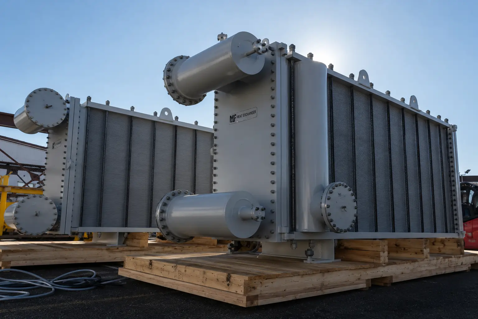
A compact heat exchanger is a heat exchanger that achieves a very high ratio of heat transfer surface area to equipment volume. Where a conventional shell and tube exchanger delivers 100–300 m² of surface per m³, a compact design delivers 700–2,500 m² per m³ — the same heat duty in a fraction of the physical space.
This high surface density comes from using corrugated plates, fins, or micro-channels instead of plain tubes. The result: smaller footprint, lower weight, less fluid inventory, and faster thermal response — properties that matter enormously in offshore platforms, mobile plants, tight process buildings, and anywhere space is a premium constraint.
As a leading compact heat exchanger manufacturer in India, United Heat Exchangers designs and fabricates gasketed plate, brazed plate, welded plate, printed circuit, and plate-fin compact heat exchangers for process industries, power generation, HVAC, marine, and refrigeration — to ASME and ISO standards, with a written thermal performance guarantee on every unit.
How a Compact Heat Exchanger Works
The operating principle is identical to any heat exchanger: two fluid streams exchange thermal energy across a conductive surface without mixing. What makes compact exchangers different is how that surface is structured — and how much of it fits into a small space.
Hot Fluid Enters
Hot process fluid enters through the inlet port and is distributed into alternating flow channels — every second channel carries the hot stream.
Cold Fluid Enters Opposite Channels
Cold fluid enters at the opposite end and occupies the remaining alternating channels — creating a true counter-current or cross-flow arrangement depending on the port geometry.
Turbulence Intensifies Heat Transfer
Corrugated plate or fin surfaces continuously disrupt the fluid boundary layer — generating high turbulence at low flow velocities. This is why compact exchangers achieve heat transfer coefficients 3–5× higher than bare tubes.
Heat Transfers Through Thin Walls
Thermal energy migrates through the thin plate or fin wall — measured in tenths of a millimetre — between adjacent hot and cold channels. Thin walls with high-conductivity metals maximise heat transfer per unit of area.
Fluids Exit Separately
The now-cooled hot fluid and the now-heated cold fluid exit through their respective outlet ports — completely separated throughout, with no cross-contamination between circuits.
💡 Why compact exchangers run closer to counter-current: The alternating channel arrangement allows true counter-current flow — hot fluid moving one direction, cold fluid moving the opposite through adjacent channels. This maximises the mean temperature difference driving heat transfer, allowing compact exchangers to achieve temperature crossovers that a shell and tube exchanger would require multiple shells to achieve.
Types of Compact Heat Exchangers
Each compact heat exchanger type uses a different channel geometry and construction method — suited to different pressure ratings, temperature ranges, fouling characteristics, and maintenance requirements.
Gasketed Plate Heat Exchanger (GPHE)
Fully disassemblable — the maintenance-first compact designCorrugated metal plates held in a frame between a fixed cover plate and a movable pressure plate, sealed by elastomeric gaskets. The entire plate pack can be separated, cleaned, inspected, and reassembled — or expanded by adding plates to increase capacity.
- Best for fouling services that require periodic mechanical plate cleaning
- Capacity adjustable — plates added or removed to change duty without replacing the frame
- Pressure limited by gasket material — typically up to 25–30 bar
- Wide fluid compatibility — gasket material selected per fluid chemistry
- Used in HVAC, dairy, food processing, chemical, and general process service
Brazed Plate Heat Exchanger (BPHE)
Sealed, compact, leak-free — no gasketsStainless steel plates copper-brazed or nickel-brazed into a single fused unit — no gaskets, no frame, no bolts. The result is a self-contained sealed exchanger, highly compact, resistant to pressure cycling, and capable of operating at pressures well above the gasketed plate limit.
- Handles pressures up to 30–45 bar depending on construction
- Immune to gasket degradation — no elastomer compatibility concern
- Smallest possible footprint for a given heat duty
- Used in refrigeration, heat pumps, hydraulic oil cooling, and solar thermal systems
- Not field-cleanable — chemical cleaning only; avoid severely fouling fluids
Welded Plate Heat Exchanger
High pressure, high temperature — no gasket limitationPlates are laser-welded or fusion-welded together in pairs to eliminate gaskets on the process side. The welded plate pairs can be housed in a bolted frame (semi-welded) or fully welded into a pressure vessel body — suited to aggressive fluids that would attack elastomeric gaskets.
- Handles aggressive chemicals, high temperatures, and high pressures beyond gasketed limits
- Semi-welded designs retain partial disassembly for one-side cleaning
- Used for refrigerants, aggressive solvents, acidic process streams
- Suitable for pressures up to 40–100 bar depending on design type
- Longer lead time than gasketed PHE — more complex fabrication
Plate-Fin Heat Exchanger
Highest surface density — cryogenic and aerospace standardCorrugated fin inserts brazed between flat separator plates, assembled into a multi-layer block. Multiple streams — sometimes three or more — can be accommodated in a single block by routing each stream through specific fin layers. Achieves surface area densities above 2,000 m² per m³.
- Used in LNG liquefaction, air separation, cryogenic processes, and gas processing
- Handles multiple fluid streams simultaneously in one unit
- Aluminium construction for cryogenic service; stainless steel for elevated temperature
- Very low pressure drop relative to heat transfer — ideal for gas-to-gas duties
- Not field-cleanable — specified only for clean, non-fouling fluid services
Printed Circuit Heat Exchanger (PCHE)
Extreme pressure and temperature — the compact benchmarkChemically etched micro-channels on flat metal plates, diffusion-bonded together under heat and pressure with no brazing material or gaskets. The result is a monolithic metal block with internal micro-channels — capable of operating at pressures exceeding 600 bar and temperatures from cryogenic to 900°C.
- Handles supercritical CO₂, hydrogen, helium, and extreme-pressure gas streams
- Used in offshore gas processing, hydrogen plants, and advanced energy systems
- 10–30× smaller and lighter than a shell and tube unit for equivalent duty
- High capital cost — justified by weight and space savings in weight-critical applications
- Not cleanable — requires ultra-clean, particle-free fluid service
Micro-Channel Heat Exchanger
Lightweight refrigerant condenser — modern HVAC standardMulti-port aluminium flat tubes with internal micro-channels, brazed to corrugated aluminium fins and assembled into a flat coil. Air flows across the fin surface; refrigerant flows through the internal micro-channels. Common in automotive air conditioning and increasingly in building HVAC condensers and evaporators.
- 30–40% lighter than conventional round-tube plate-fin coils
- Lower refrigerant charge — reduced inventory and environmental impact
- Used in commercial HVAC, industrial refrigeration, and automotive cooling
- Sensitive to particulate fouling — requires adequate air filtration on inlet
- Not field-repairable — replacement of individual coil sections required on damage
Key Components Explained
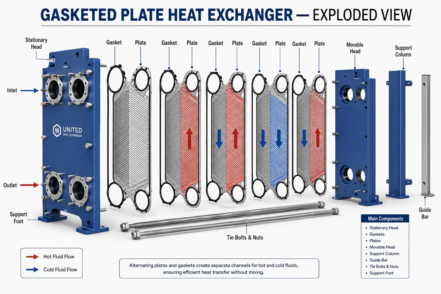
Gasketed plate heat exchanger — fixed cover, corrugated plate stack, alternating hot and cold channels, gaskets, and movable pressure plate
Corrugated Plates
The heat transfer surface. Pressed from thin metal sheet into a herringbone or chevron corrugation pattern. The corrugations serve two purposes: they create turbulence in the fluid stream, raising the heat transfer coefficient, and they act as structural supports between adjacent plates, allowing thin-wall construction at surprisingly high pressures.
Gaskets (Gasketed PHE)
Elastomeric seals bonded to the plate perimeter. They define the flow path — routing each fluid into its own alternating channels — while sealing the plate pack against external leakage. Gasket material is selected per fluid chemistry and temperature: NBR, EPDM, Viton, or PTFE-encapsulated grades for aggressive fluids.
Frame — Fixed and Movable Cover Plates
Heavy steel cover plates at each end of the plate stack. The fixed cover plate carries the inlet and outlet nozzles. The movable pressure plate slides on the carry bar and is drawn toward the fixed plate by tightening bolts — compressing the plate stack to the correct gasket seating force. Loosening the bolts separates the plates for cleaning.
Carry Bar and Support Column
The horizontal top bar on which all plates hang and slide for assembly, disassembly, and plate count adjustment. The lower guide bar maintains plate alignment. The vertical support column at the far end is the structural tie point for the compression bolts. These three components form the frame that makes the gasketed PHE user-maintainable in the field.
Inlet and Outlet Nozzles
Flanged connections on the fixed cover plate routing each fluid into and out of the plate pack. In a standard two-fluid design, four nozzles are provided — two per fluid circuit, at diagonal corners of the cover plate — creating the counter-current flow arrangement that maximises the mean temperature difference.
Brazing Filler (Brazed PHE)
In a brazed plate heat exchanger, copper or nickel filler metal replaces gaskets and the frame entirely. The plate stack is assembled dry, placed in a furnace, and brazed at high temperature — the filler flows into every gap by capillary action and solidifies into a leak-free sealed block. No external frame, no bolts, no gaskets to replace.
Compact vs Shell and Tube — When to Choose Which
Compact heat exchangers are not a universal replacement for shell and tube. They excel in specific conditions — and underperform in others. The right selection depends on four factors: pressure, fouling, temperature differential, and the physical space available.
Choose Compact When
These conditions favour compact heat exchanger design
- Space is severely constrained — offshore platforms, mobile skids, tight process buildings
- Weight is critical — vessel weight budgets, elevated structures, transportation limits
- Both fluids are relatively clean — low fouling tendency, manageable with CIP cleaning
- Close temperature approach is required — compact counter-current geometry achieves tighter ΔT than multi-shell shell-and-tube trains
- Fluid inventory needs to be minimised — compact designs hold far less fluid volume per unit of heat duty
- Thermal response speed matters — small fluid volume means faster temperature stabilisation at process changes
- Moderate operating pressures — gasketed PHE up to 25 bar; BPHE up to 45 bar; welded PHE up to 100 bar
Choose Shell and Tube When
These conditions favour conventional shell and tube design
- Tube-side fluid is heavily fouling and requires periodic mechanical cleaning
- Operating pressure exceeds the practical limit for plate designs — high-pressure hydrogen, supercritical service
- Operating temperature is extreme — above 350°C or below -100°C on standard plate materials
- Fluid contains abrasive particles that would erode thin plate surfaces
- Two-phase shell-side service with large vapour-to-liquid volume change — kettle reboilers, steam generators
- Lethal or toxic fluid service requiring absolute leak containment with no gasket risk
- Large temperature differentials requiring free thermal expansion — U-tube or floating head designs
💡 The hybrid approach: Many modern process plants use compact exchangers for clean low-pressure duties and shell and tube for fouling or high-pressure services within the same unit. United Heat Exchangers manufactures both — and recommends the right type for each duty in your process, not a single technology for all applications.
Design Specifications and Standards
Every compact heat exchanger is custom-engineered to your specific process data — thermally sized for your duty, fluid chemistry, fouling resistance, and pressure drop constraint.
| Specification | Range / Options |
|---|---|
| Type | Gasketed PHE, brazed PHE, welded PHE, semi-welded PHE, plate-fin, PCHE, micro-channel |
| Design Pressure | Full vacuum to 25 bar (gasketed PHE); up to 45 bar (BPHE); up to 100 bar (welded PHE); up to 600+ bar (PCHE) |
| Design Temperature | -196°C to +900°C depending on type and materials — cryogenic to high-temperature process service |
| Plate Material | 304 / 316L stainless steel, duplex 2205, super duplex 2507, titanium Gr.1 / Gr.2, Hastelloy C-276, Inconel 625, aluminium (plate-fin and micro-channel) |
| Gasket Material | NBR, EPDM, Viton (FKM), PTFE-encapsulated Viton, compressed fibre — selected per fluid chemistry and temperature |
| Brazing Filler | Copper brazing (standard BPHE), nickel brazing (for ammonia, drinking water, and aggressive chemical service) |
| Plate Corrugation | Herringbone / chevron pattern — high-theta (high ΔP, high HTC) or low-theta (low ΔP, lower HTC) — mixed plate packs for balanced optimisation |
| Number of Plates | 10 to 700+ plates per frame depending on duty and plate size |
| Connections | Flanged, threaded, or welded nozzles to ANSI, DIN, or customer standard |
| Number of Fluid Circuits | 2 circuits standard; 3 or 4 circuits available in multi-pass and plate-fin designs |
| Frame Material | Carbon steel (painted or galvanised), stainless steel for food, pharma, and corrosive atmosphere service |
| Design Code | ASME BPVC Section VIII Div. 1 (pressure vessel rated units); PED (Europe); AD-2000 (Germany); API 662 (petroleum service plate heat exchangers) |
| Surface Area Range | 0.1 m² (small BPHE) to 3,000 m² per frame (large gasketed industrial PHE) |
| Thermal Rating Software | HTRI Xchanger Suite — written performance guarantee issued with every unit |
Material Selection Guide
Plate material selection is the most critical decision in compact heat exchanger design. The thin-wall geometry maximises heat transfer — but it also means that any corrosion progresses to perforation faster than in a thick-walled shell and tube. It is imperative that the material be chosen correctly throughout the design phase.
304 Stainless Steel
Standard plate material for clean process fluids, hot water, HVAC circuits, and food-grade service at moderate temperatures. Adequate chloride resistance for low-chloride applications. Not suitable for seawater or chloride-containing process streams above trace concentrations.
316L Stainless Steel
Improved chloride resistance over 304 — the most widely used plate material for general chemical and process service. Suitable for moderate chloride concentrations, mild acids, and amine solutions. Low-carbon grade avoids sensitisation at weld-adjacent plate zones.
Duplex 2205
Twice the yield strength of 316L — allowing thinner plates at the same pressure rating — with outstanding resistance to chloride stress corrosion cracking. Specified for seawater cooling, chloride-containing process streams, and coastal industrial atmospheres where 316L SCC failure is a documented risk.
Super Duplex 2507
The standard for dependable seawater and aggressive brine service is PREN over 40. Specified for offshore produced water coolers, desalination pre-heaters, and high-chloride chemical duties where duplex 2205 provides insufficient pitting resistance margin.
Titanium Grade 1 / Grade 2
The material of choice for seawater, wet chlorine, and hypochlorite service. Essentially immune to chloride pitting and crevice corrosion at typical marine operating temperatures. The standard plate material for seawater-cooled compact heat exchangers in power, desalination, and offshore applications.
Hastelloy C-276
Nickel-molybdenum-chromium alloy — specified for concentrated acids, mixed acid environments, and chemical process streams that defeat austenitic and duplex stainless steels. Used in compact exchangers for phosphoric acid, sulphuric acid, and aggressive mixed-phase chemical services.
Aluminium (Plate-Fin and Micro-Channel)
Standard material for cryogenic plate-fin exchangers in LNG and air separation service, and for micro-channel refrigerant coils in HVAC and automotive applications. High thermal conductivity, low weight, and excellent cryogenic toughness — but not suitable for alkaline fluids or chloride-containing aqueous service.
Nickel-Brazed BPHE (Ammonia Service)
Copper brazing is incompatible with ammonia refrigerant — ammonia attacks copper. Nickel-brazed BPHEs use a nickel filler that is fully ammonia-compatible, making them the standard specification for brazed plate exchangers in industrial ammonia refrigeration systems.
Industries and Applications
| Industry | Typical Application | Type Specified |
|---|---|---|
| HVAC and Building Services | Chilled water circuit isolation, district cooling heat interface units, domestic hot water heating, heat pump evaporators and condensers | Gasketed PHE for large building plant; BPHE for compact rooftop and close-coupled units |
| Industrial Refrigeration | Ammonia evaporators and condensers in cold storage, food processing, and industrial cooling systems | Nickel-brazed BPHE for ammonia service; gasketed PHE for large industrial ammonia plants |
| Oil and Gas Processing | Lean/rich amine heat exchangers, glycol regenerator trim coolers, instrument air coolers, lube oil coolers on compressor skids | Welded or semi-welded PHE for amine service; gasketed PHE where periodic cleaning is required |
| Offshore Platforms | Seawater cooling of process streams, closed cooling water coolers, HVAC unit coolers — space and weight are critical constraints | Titanium gasketed PHE for seawater service; BPHE for small skid-mounted utilities |
| Chemical Processing | Reactor feed-product heat recovery, solvent coolers and heaters, acid coolers, distillation feed pre-heaters | Welded PHE for aggressive chemicals; gasketed PHE for cleanable moderate-fouling duties; BPHE for clean low-pressure services |
| Power Generation | Closed cooling water heat exchangers, lube oil coolers, hydrogen coolers for generators, condensate polishing coolers | Gasketed PHE for large plant utility cooling; BPHE for small generator auxiliary services |
| LNG and Cryogenics | Liquefaction cold boxes, air separation cold boxes, natural gas dew point control, boil-off gas condensers | Aluminium plate-fin for multi-stream cryogenic duties; PCHE for extreme-pressure cryogenic service |
| Food and Beverage | Milk pasteurisation, beer and beverage cooling, juice heating, CIP (clean-in-place) compatible process coolers | Gasketed PHE in hygienic frame design — fully disassemblable, electropolished plates, FDA-compliant gasket materials |
| Pharmaceutical and Biotech | WFI (water for injection) heating and cooling, sterile process fluid temperature control, clean steam condensing | Gasketed PHE or BPHE in 316L with electropolished surfaces — full material traceability for regulated service |
| Marine and Shipbuilding | Engine central coolers, jacket water coolers, lube oil coolers, freshwater generator heat exchangers, HVAC sea water coolers | Titanium or CuNi gasketed PHE for seawater service; BPHE for small auxiliary marine duties |
Compact Heat Exchangers for Every Industry — Maximum Duty, Minimum Space
From a single BPHE on a compressor skid to a multi-frame titanium PHE train for offshore seawater cooling — ASME certified, HTRI thermal guaranteed, full documentation. Free quote in 48 hours.
Request My Free Quote →How to Choose the Best Compact Heat Exchanger
Six questions, answered before any sizing work begins, determine the right compact heat exchanger type for your application.
What Is the Operating Pressure?
Below 25 bar and clean service — gasketed PHE is the first choice. 25–45 bar — BPHE or welded PHE. Above 45 bar — welded or semi-welded PHE, or PCHE for extreme pressure. Pressure is the first filter that narrows the type selection.
Are the Fluids Fouling?
Clean fluids — BPHE or welded PHE delivers the smallest footprint and lowest cost. Moderate fouling — gasketed PHE allows plate removal and mechanical cleaning. Heavy fouling — reconsider shell and tube; compact exchangers are not suited to tube-side fouling services requiring mechanical rodding.
What Is the Temperature Range?
Standard service up to 180°C — all PHE types available. Up to 350°C — welded PHE with high-temperature gasket or gasketed PHE with Viton. Above 350°C — plate-fin in stainless or PCHE in stainless or nickel alloy. Cryogenic to -196°C — aluminium plate-fin.
How Aggressive Is the Fluid Chemistry?
316L plates for mild process fluids or clean water. Seawater or chloride-containing titanium or duplex. Concentrated acids or mixed aggressive chemicals — Hastelloy C-276. Ammonia refrigerant — nickel-brazed BPHE or 304/316 gasketed PHE (no copper brazing).
How Often Does Cleaning Access Matter?
Frequent plate cleaning required — gasketed PHE only. Occasional CIP chemical cleaning acceptable — BPHE or welded PHE. No cleaning expected over the unit's life — PCHE or plate-fin on ultra-clean services. Maintenance access philosophy drives the choice between gasketed and non-gasketed types.
What Is the Space and Weight Budget?
Standard industrial — any PHE type. Space-critical offshore platform or mobile skid — BPHE or welded PHE for minimum footprint. Weight-critical or multi-stream cryogenic — plate-fin. Extreme weight and space saving at very high pressure — PCHE. Space and weight constraints are the final differentiator between equivalent-pressure options.
Maintenance Guide
Compact heat exchangers maintained correctly retain their original thermal performance for their full design life. The maintenance approach varies by type — gasketed PHEs are field-maintainable; BPHEs and welded types require chemical cleaning.
| Task | Applies To | Frequency | Action |
|---|---|---|---|
| Performance Monitoring | All types | Continuous — log ΔT and pressure drop | Track heat transfer approach temperature and pressure drop across both circuits against commissioning baseline. A rising approach ΔT at constant flow rates is the earliest fouling indicator — act before it becomes a process constraint |
| Mechanical Plate Cleaning | Gasketed PHE only | As indicated by performance monitoring — typically annually for moderate fouling | Loosen compression bolts, separate plate pack, brush or water-wash each plate face, inspect gasket seating surfaces, replace any damaged gaskets, reassemble to the manufacturer's minimum and maximum compression length |
| Chemical CIP Cleaning | All types | As indicated by performance or at scheduled intervals | Circulate an approved cleaning solution — acid descaler for mineral scale, alkaline cleaner for biological or organic fouling — at the manufacturer's recommended concentration and contact time. Flush thoroughly with clean water before returning to service |
| Gasket Inspection and Replacement | Gasketed PHE | Every mechanical disassembly; or at maximum 5-year intervals | Inspect all gaskets for compression set, cracking, swelling, or chemical attack. Replace any gasket showing visible degradation. Never reuse gaskets that have been compressed beyond their elastic recovery limit |
| Plate Inspection | Gasketed PHE | Every mechanical disassembly | Check all plate surfaces for pitting, erosion at corrugation peaks (inlet erosion), crevice corrosion at gasket grooves, and any perforations. Replace plates showing through-wall corrosion or mechanical damage — do not attempt to weld-repair thin PHE plates in the field |
| Compression Bolt Torque Check | Gasketed PHE | After every reassembly; 6-monthly otherwise | Check compression dimension against the nameplate value. Retighten uniformly if the measured dimension exceeds the maximum compression length. Uneven bolt torque causes plate misalignment and cross-contamination leaks |
| Nozzle and Connection Inspection | All types | Annual | Inspect all inlet and outlet nozzle flanges and gaskets for leakage, corrosion, and flange face condition. Tighten or replace as needed. BPHEs with brazed nozzles should be checked for joint integrity by pressure observation |
| Frame and Bolt Condition | Gasketed PHE | Annual | Lubricate compression bolts and inspect for thread wear, corrosion, and straightness. Inspect carry bar and support column for corrosion. Clean and touch-up coating damage on frame steelwork to prevent progressive corrosion at the base of the unit |
💡 Log the compression dimension at every reassembly. The distance between the fixed cover plate and the movable pressure plate is the most reliable indicator of gasket condition over time. If the same bolt torque results in a shorter compression distance at each reassembly, the gaskets are taking a permanent set — they will need replacement at the next disassembly before leakage begins.
Why United Heat Exchangers
A compact heat exchanger that occupies half the space of a shell and tube unit only delivers value if it performs reliably at the rated duty throughout its service life. That requires correct plate selection for the fluid chemistry, accurate fouling resistance assessment, and a thermal design that accounts for your actual operating range — not just the design point. This is the standard United Heat Exchangers applies to every compact heat exchanger we deliver.
35+ Years of Heat Exchanger Manufacturing
Established in 1989. Compact, shell and tube, air cooled — all heat exchanger types are our core product. The manufacturing knowledge base built over three and a half decades applies to every unit we design.
HTRI Thermal Design — Written Guarantee
Every compact heat exchanger is thermally sized using HTRI Xchanger Suite. We issue a written thermal performance guarantee with every unit — not a datasheet estimate. The unit performs to the rated duty at your stated operating conditions.
ASME Certified — Full Documentation
Pressure-rated compact heat exchangers are manufactured to ASME BPVC Section VIII where applicable, with U-Stamp MDR, material certifications, and hydrostatic test certificates issued as a complete documentation package.
Right Plate Material for Your Fluid
We assess fluid chemistry, temperature, chloride content, and pH and specify the plate material that delivers the required service life. 316L where adequate; titanium, duplex, or Hastelloy where it is not. No generic default material applied across all enquiries.
All Compact Types — One Manufacturer
Gasketed PHE, brazed PHE, welded PHE, plate-fin, and PCHE — all supplied under one quality system and one contract. No need to qualify multiple suppliers for different compact heat exchanger types in your project.
Spare Plates and Gaskets Available
Replacement plates and gaskets for every gasketed PHE we supply are held in stock or manufactured to order within the stated lead time — supporting your maintenance programme over the full operational life of every unit.
Delivery and What's Included
What's Included with Every Compact Heat Exchanger Order
- Written HTRI thermal performance guarantee — rated for your specific process duty, fluid properties, and fouling resistances
- ASME U-Stamp documentation (where applicable) — Manufacturer's Data Report signed by the Authorised Inspector for pressure-rated units
- Material certifications (MTRs) — mill test reports for all plates, frame components, and nozzles; traceable to heat and lot number
- Hydrostatic test certificate — both circuits tested to 1.5× design pressure; test witnessed and recorded
- Plate layout drawing — plate arrangement, pass configuration, and channel flow path for the supplied unit
- Gasket material data sheet — chemical compatibility confirmation for the specified fluid and temperature for gasketed PHE units
- Compression dimension record — minimum and maximum plate pack compression length for gasketed PHE, recorded as the maintenance baseline
- Operation and maintenance manual — disassembly and reassembly procedure, plate cleaning guide, CIP cleaning protocol, torque sequence, and spare parts list
- Spare parts recommendation — suggested first-year and long-term spare plates and gaskets identified by item number for reorder
- Lifetime technical support — thermal re-rating, plate count change, plate material upgrade, and performance troubleshooting throughout every unit's service life
Get a Free Compact Heat Exchanger Quote in 48 Hours
Share your hot and cold fluid types, flow rates, inlet and outlet temperatures, design pressure, fouling nature, operating temperature range, and any space or weight constraints. Our engineering team selects the right type, sizes the unit, and delivers a technical proposal within 48 hours.
Request My Free Quote →Frequently Asked Questions
What is a compact heat exchanger?
A compact heat exchanger achieves a very high ratio of heat transfer surface area to equipment volume — typically 700 to 2,500 m² per m³, versus 100–300 m² per m³ for a shell and tube exchanger. This high surface density means the same heat duty handled in a fraction of the physical space and weight, using corrugated plates, fins, or etched micro-channels instead of plain tubes.
What distinguishes a brazed plate heat exchanger from a gasketed plate heat exchanger?
A gasketed PHE uses elastomeric gaskets and a bolted frame — fully disassemblable for plate cleaning and inspection, and expandable by adding plates. A brazed PHE fuses all plates into a sealed block using copper or nickel brazing filler — no gaskets, no frame, smallest possible footprint, but not field-cleanable. Choose gasketed for fouling services; choose brazed for clean fluids where minimum size and no gasket maintenance are the priorities.
Can compact heat exchangers handle high operating pressures?
It depends on the type. Gasketed PHEs are limited to approximately 25 bar by the gasket sealing capacity. Brazed PHEs reach 30–45 bar. Welded and semi-welded PHEs handle up to 100 bar. Printed circuit heat exchangers (PCHE) operate at pressures exceeding 600 bar — making them suitable for high-pressure gas, hydrogen, and supercritical fluid services that no plate type can handle.
Which compact heat exchanger plate material is correct for seawater service?
Titanium Grade 1 or Grade 2 is the standard specification for direct seawater contact — essentially immune to chloride pitting and crevice corrosion at marine operating temperatures. Super duplex 2507 is a cost-competitive alternative for moderate seawater temperatures and velocities. Because of its thin plate wall and tight gasket crevices, standard 316L stainless steel is unsuitable for direct saltwater contact in small heat exchangers, which can lead to quick chloride pitting failure.
Are compact heat exchangers suitable for ammonia refrigerant service?
Yes — with the correct material specification. Copper-brazed BPHEs are not compatible with ammonia because ammonia attacks copper. The correct specification for ammonia service is a nickel-brazed BPHE or a gasketed PHE with 304 or 316 stainless steel plates and ammonia-compatible gasket material (EPDM or PTFE-encapsulated Viton). United Heat Exchangers confirms material compatibility for every ammonia service enquiry before sizing.
How can I determine whether a compact heat exchanger is the best option for my needs?
If your operating pressure is below 100 bar, both fluids are relatively clean, space or weight is constrained, and you need a close temperature approach — a compact heat exchanger is almost certainly the right choice. If your tube-side fluid is heavily fouling and requires mechanical rodding, or if operating temperature and pressure exceed the practical limits of plate designs, a shell and tube design is more appropriate. United Heat Exchangers evaluates both options for every enquiry and recommends based on the actual service conditions.
Can I add plates to a gasketed plate heat exchanger to increase capacity?
Yes — provided the existing frame has sufficient compression length to accommodate additional plates. When ordering a gasketed PHE, it is good engineering practice to specify the frame with spare compression space for one or two future plate additions. United Heat Exchangers notes the maximum plate capacity of the supplied frame in every order, and confirms compatibility before supplying supplementary plates.
What is the delivery time for a compact heat exchanger from United Heat Exchangers?
Standard gasketed PHE and BPHE units in 316L stainless or titanium deliver in 3–6 weeks from order confirmation. Welded PHE, large plate-fin blocks, PCHE units, and special alloy constructions deliver in 8–16 weeks. Expedited schedules for shutdown and replacement units are available on request.
Author: Senthil Kumar, Technical Director — United Heat Exchangers Pvt. Ltd. | Last Updated: May 2026