Author: Senthil Kumar, Technical Director | Updated: June 2026
Table of Contents

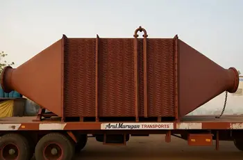
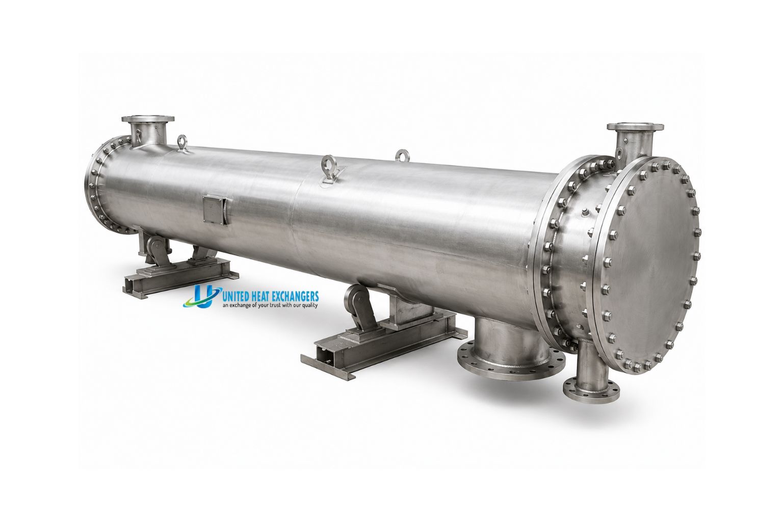
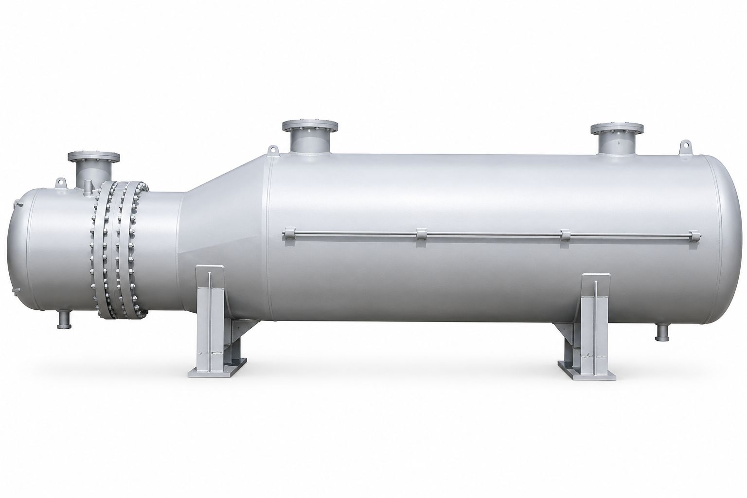
A shell-and-tube heat exchanger is an industrial device that heats or cools process fluids by transferring heat between two liquids or gases without allowing them to touch or mix. One fluid flows through a bundle of tubes, while the other flows through the outer shell. The design handles single-phase and two-phase duties — heating, cooling, condensing, and vaporising — making it the most widely used heat exchanger type across oil and gas, refinery, chemical, power, and marine industries.
United Heat Exchangers designs and manufactures shell-and-tube heat exchangers to TEMA and ASME Section VIII, with over 35 years of experience supplying fixed tube sheet, U-tube, floating head, and kettle reboiler configurations to clients across India and 30+ countries.
Products
United Heat Exchangers manufactures all principal TEMA shell and tube configurations. The right design depends on your process fluid, operating temperature, fouling tendency, and whether the bundle must be removable for cleaning.
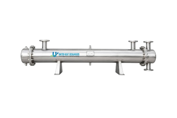
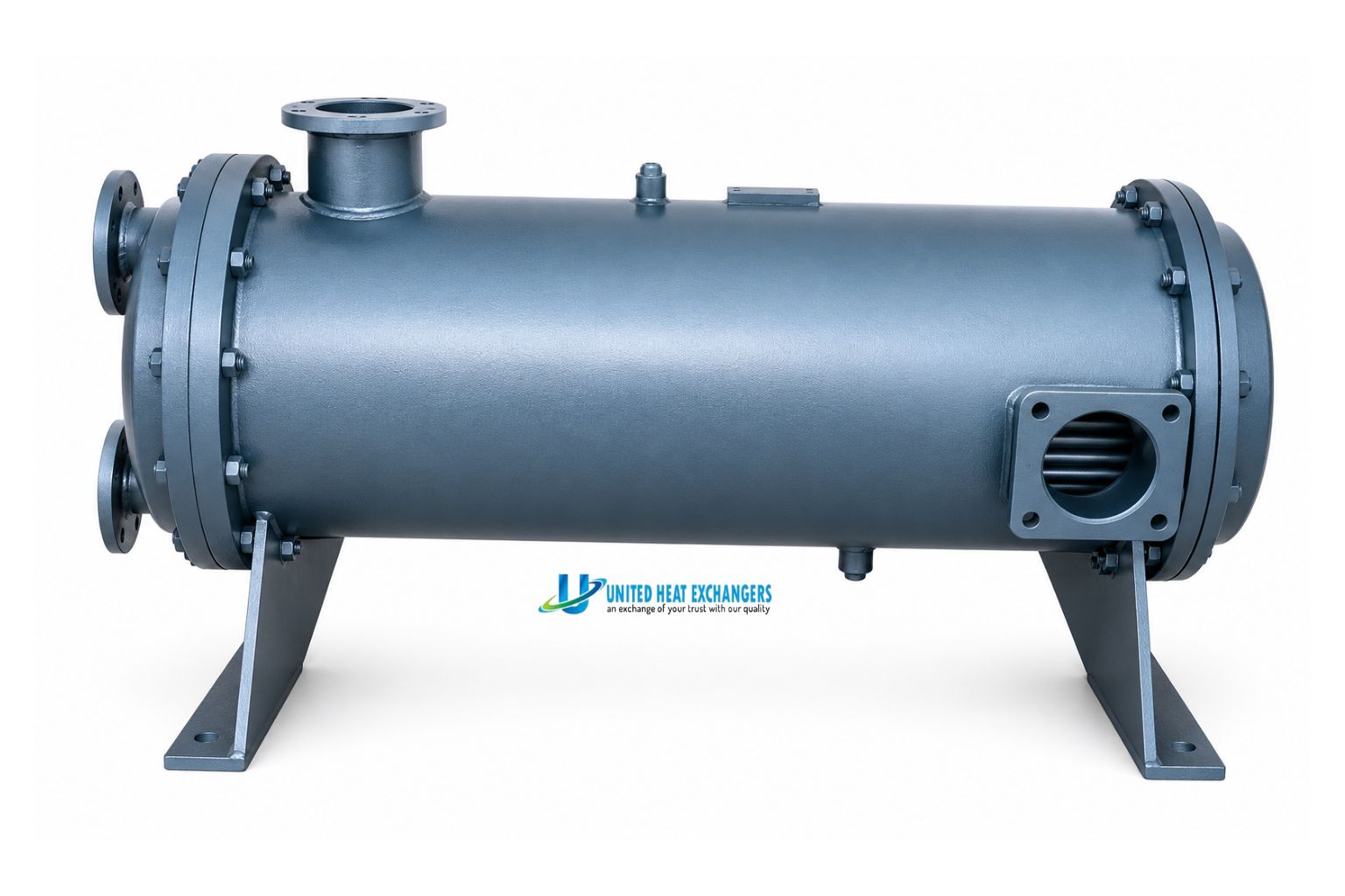
Both tube sheets are welded rigidly to the shell. The simplest and most cost-effective design — no floating components, minimum parts, no packed joints.
- Lowest capital cost of all TEMA configurations
- Expansion bellows added when differential thermal expansion is significant
- Best for clean shell-side fluids where chemical cleaning is acceptable
- Standard for utility cooling, steam condensing, and clean process duties
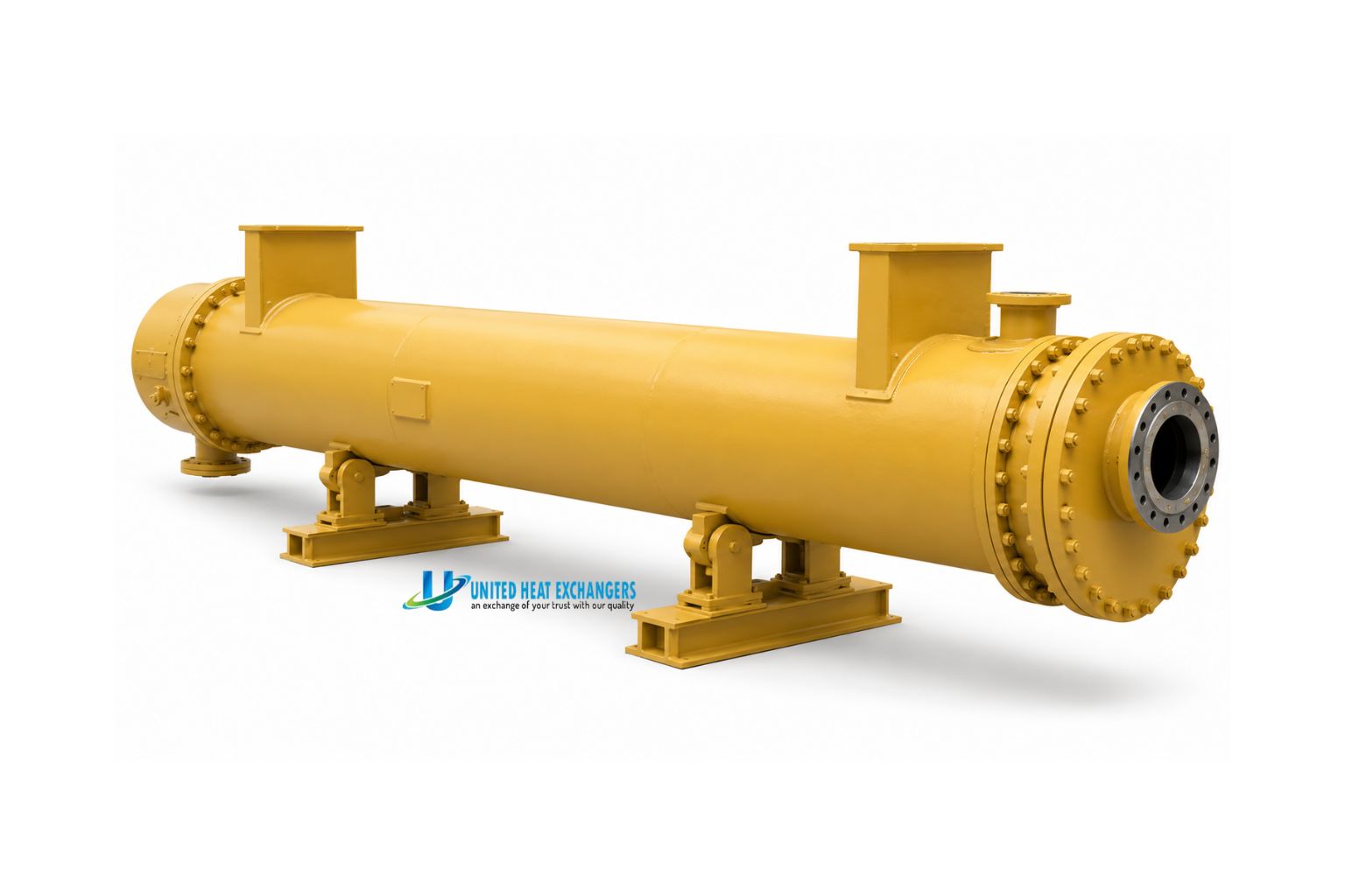
Tubes are bent into a U-shape with both ends on a single tube sheet — The bundle expands freely, eliminating thermal stress on the shell and tubes.
- Unrestricted thermal expansion — no differential expansion stress
- Bundle fully removable for shell-side inspection and cleaning
- Single tube sheet — fewer potential leak points
- Ideal for high-temperature, high-pressure, and clean tube-side services
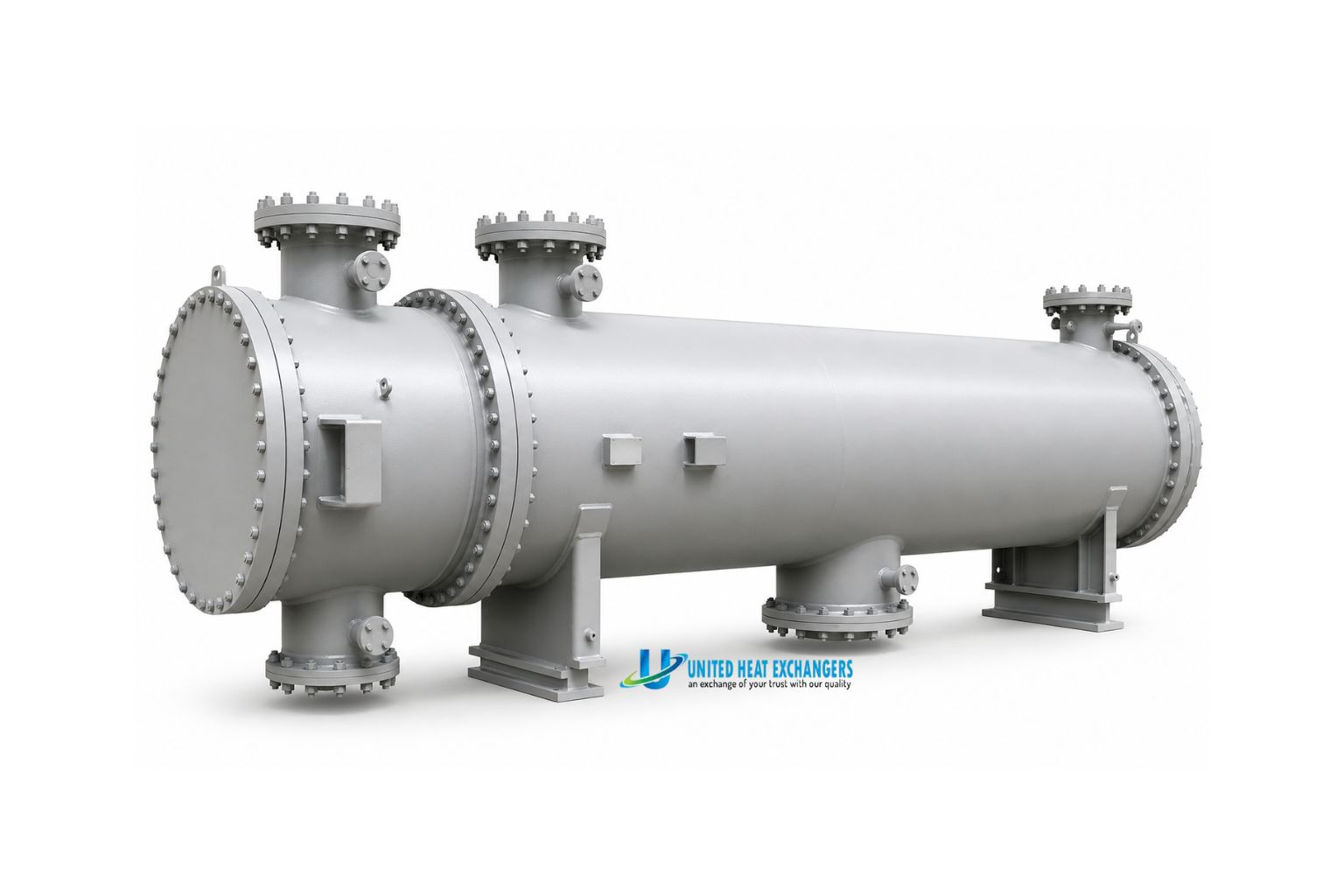
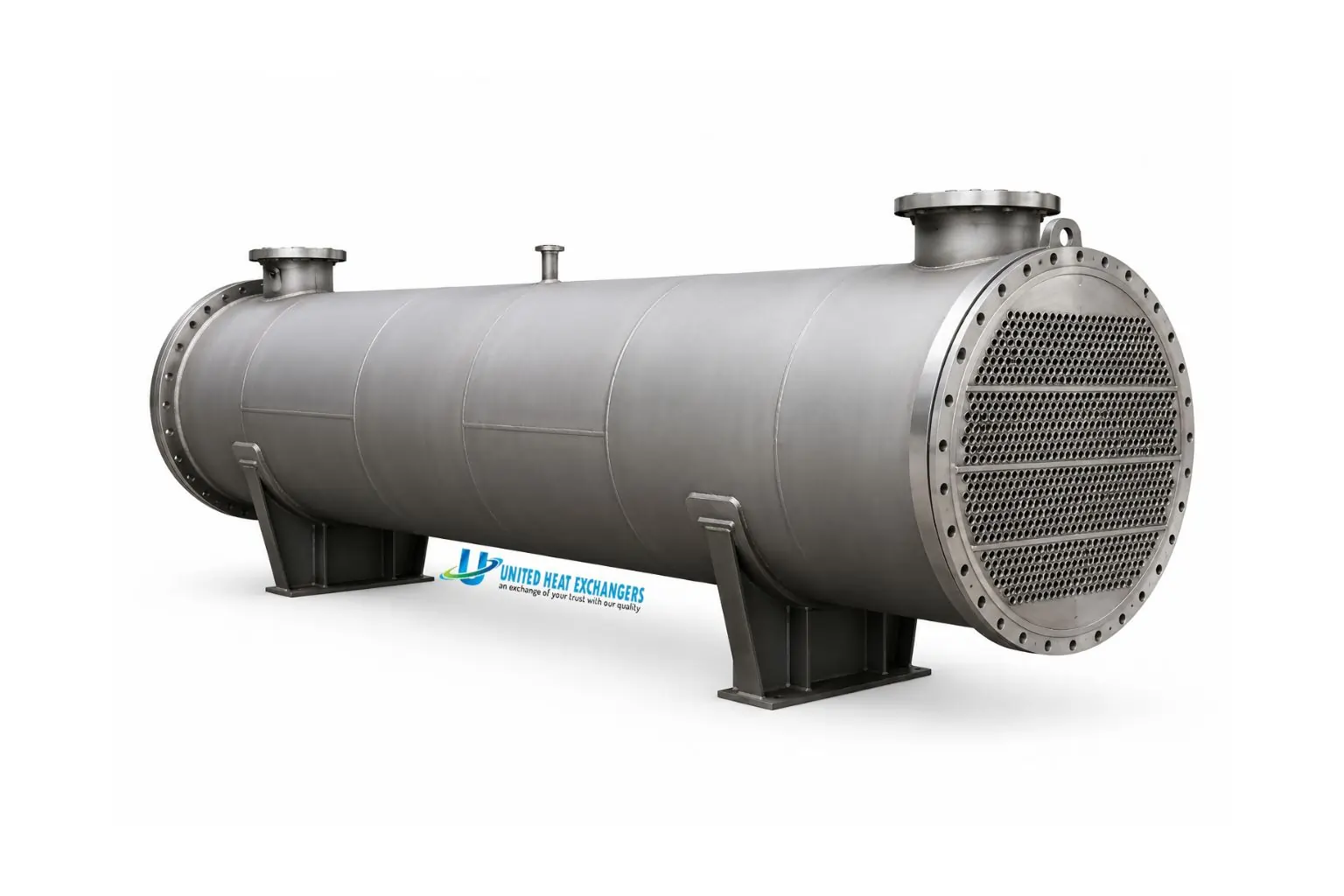
One tube sheet floats freely inside the shell, accommodating thermal expansion. The entire bundle withdraws from the shell for complete mechanical cleaning of both sides.
- Bundle fully removable — both shell and tube sides mechanically cleanable
- Floating tube sheet absorbs large differential thermal expansion
- TEMA Type S (split backing ring) standard for refinery and chemical service
- Preferred for crude oil, heavy hydrocarbon, and fouling process duties
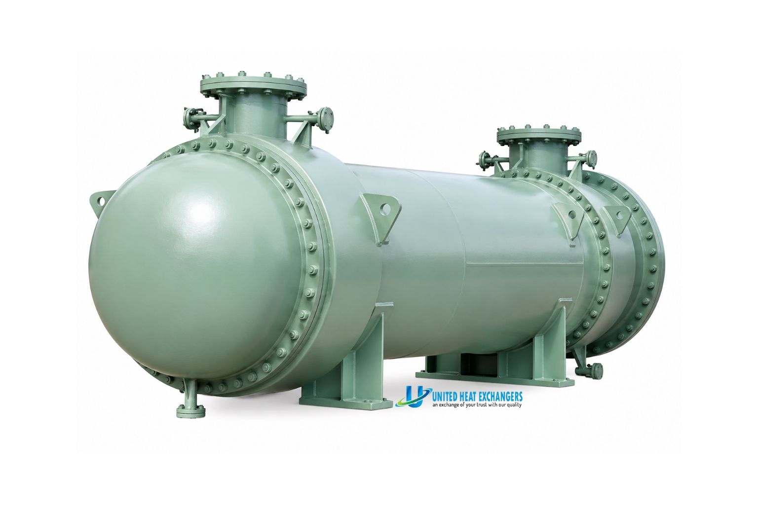
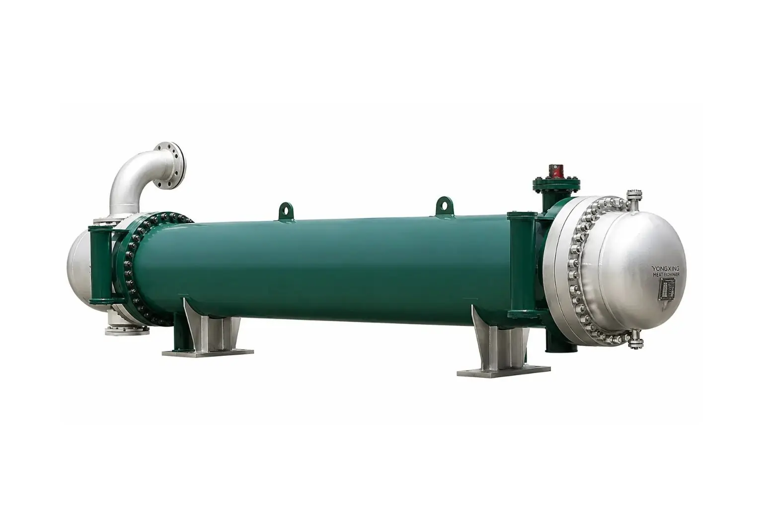
A U-tube or floating head bundle sits inside an oversized shell with vapour disengagement space above the bundle. A weir controls the liquid level to keep the bundle fully submerged.
- Oversized shell provides clean vapour–liquid separation above the bundle
- Weir ensures bundle stays fully submerged at all operating conditions
- Standard reboiler design for distillation column bottom service
- Available with U-tube or floating head bundle per fouling requirement
Not sure which configuration is right? Share your process duty — fluid names, flow rates, temperatures, pressure, and fouling tendency — and our engineering team will recommend the correct TEMA configuration, material selection, and ASME class within 48 hours.
Features
United Heat Exchangers shell-and-tube heat exchangers are custom-engineered to your process — not selected from a catalogue. Every unit is thermally rated in HTRI Xist and mechanically validated in PV Elite before a single plate is cut.
High Thermal Efficiency
Optimized tube bundle geometry — tube pitch, baffle spacing, baffle cut, and pass arrangement — maximizes heat transfer while minimizing pressure drop on both sides. HTRI Xist confirms every design before fabrication.
Wide Range of Temperatures and Pressures
Handles duties from full vacuum to 350 bar and −196°C to 650°C — a range no other heat exchanger type matches. Built for demanding industrial environments where reliability is non-negotiable.
Handles Any Process Medium
Clean or fouling, viscous or low-viscosity, corrosive or non-corrosive — tube and shell material is selected specifically for your process fluid. Carbon steel, 316L SS, duplex, Hastelloy, titanium, and copper-nickel are all available.
ASME and TEMA Compliant
Every pressure-containing component is designed to ASME Section VIII Division 1, while TEMA mechanical standards govern tube sheet sizing, baffle spacing, nozzle reinforcement, and fabrication tolerances.
Low Maintenance Design
Floating head and U-tube designs allow full bundle withdrawal for mechanical tube and shell-side cleaning. Removable channel covers give tube-side access without disturbing shell-side piping. Designed for minimal downtime.
Leak-Proof, Rigorous Quality Testing
Every unit undergoes shell-side and tube-side hydrostatic testing at 1.3× MAWP, NDE of all pressure welds, and final dimensional inspection before dispatch — witnessed by an Authorised Inspector where required.
Industry-Specific Designs
Marine-approved materials and compact designs for shipboard installations. Hygienic, smooth-bore tube configurations for pharmaceutical and food processing. Sour-service compliance to NACE MR0175 for oil and gas duty.
Complete In-House Engineering
From thermal sizing and TEMA data sheet through to ASME calculations, fabrication drawings, NDE, and final documentation — everything under one roof. No subcontracting of critical engineering or inspection operations.
What Makes United Heat Exchangers Different: Every shell-and-tube heat exchanger begins with our engineering team — not a sales catalogue. We optimize tube bundle geometry, baffle arrangement, and pass configuration using HTRI Xist to guarantee thermal performance at your specified operating conditions. Combined with PV Elite mechanical design and complete in-house fabrication, this delivers a unit that performs exactly as calculated from day one.
How It Works
A shell-and-tube heat exchanger circulates two fluids through separate paths — they never mix. Heat transfers through the tube walls from the hotter fluid to the cooler one. The design is straightforward, proven, and capable of handling virtually any industrial heating or cooling duty.

Hot Fluid Enters
The hotter fluid enters through its inlet nozzle — either the shell side or tube side, depending on which placement suits your process.
Flows Through Its Path
Tube-side fluid passes through the tube bundle in one or more passes. Shell-side fluid flows across the tubes inside the outer shell.
Baffles Boost Transfer
Segmental baffles direct the shell-side fluid across the tube bundle repeatedly — increasing turbulence, eliminating dead spots, and maximizing heat transfer rate.
Heat Transfers Through Tube Walls
Heat moves from the hotter stream through the tube wall to the cooler stream. Counter-current flow gives the highest temperature driving force.
Fluids Exit Separately
Both fluids leave through separate outlet nozzles — cooled, heated, condensed, or vaporised — ready for the next step in your process.
Counter-Current Flow: Most shell-and-tube heat exchangers use counter-current flow — the two fluids travel in opposite directions — to achieve the highest log mean temperature difference (LMTD) and the most thermally efficient design. Where a single-pass arrangement would require an impractically long shell, multi-pass tube-side configurations achieve the same efficiency within a standard shell length.
Services
Keep your shell-and-tube heat exchangers at peak performance with United Heat Exchangers' professional service and support — from commissioning through to long-term maintenance, repair, and performance upgrades.
Installation and Commissioning
On-site installation supervision and commissioning to ensure correct alignment, nozzle make-up, Hydrostatic testing, and safe first operation to design conditions.
Preventive Maintenance
Scheduled maintenance programmes to maintain heat transfer efficiency, prevent fouling build-up, extend equipment life, and reduce unplanned downtime.
Inspection and Troubleshooting
Our engineers inspect for tube leaks, corrosion, fouling, baffle damage, and thermal underperformance — then recommend the most cost-effective corrective action.
Mechanical and Chemical Cleaning
High-pressure water jet, mechanical rodding, and chemical descaling to remove scale, sludge, and deposits — restoring heat transfer coefficients to as-new levels.
Repair and Re-tubing
Tube plugging, partial or full re-tubing, tube sheet repair, gasket replacement, and channel cover refurbishment to restore design performance and extend service life.
Performance Upgrades
Re-rating for changed process conditions, baffle modification to reduce pressure drop, tube insert installation to boost tube-side coefficient, and bundle replacement with upgraded materials.
Genuine Spare Parts
Tubes, gaskets, tube sheets, channel covers, baffles, and fasteners supplied from original material specifications with full traceability — no substitution, no compromise on quality.
Annual Maintenance Contracts (AMC)
Scheduled inspections, preventive maintenance visits, Priority emergency response, and technical assistance — all under a fixed annual contract for budget certainty.
Industries we support:
Why United Heat Exchangers
35+ Years of Experience
Over three decades of shell-and-tube heat exchanger design and manufacturing from Coimbatore — serving oil and gas, refinery, petrochemical, power, and marine clients in India and internationally.
Certified to International Standards
ASME U-Stamp for all pressure-containing components. TEMA B, C, and R class designs. IBR approval for steam-service units. NACE MR0175 compliance for sour service. ISO 9001:2015 certified quality system.
Fast Response and Technical Support
48-hour thermal sizing and budgetary proposal from your process datasheet. Experienced engineers available for equipment selection, design review, and after-sales technical support throughout the unit's service life.
Reliable Supply — India and Worldwide
shell-and-tube heat exchangers exported to 30+ countries with ASME, TEMA, NACE, and PED documentation. In-house export packing, marine insurance, and freight coordination — single-point responsibility from design to delivery.
Get a Free shell-and-tube heat exchanger Quote in 48 Hours
Send your process duty, fluid properties, allowable pressure drop, and preferred TEMA configuration. We return an HTRI-rated thermal proposal and completed TEMA data sheet within 48 hours.
Request My Free Quote →Delivery & What's Included
- HTRI Xist thermal performance guarantee — heat transfer and pressure drop at design conditions with overdesign margin and fouling allowance documented
- Completed TEMA data sheet — shell type, tube layout, baffle configuration, nozzle schedule, and TEMA class confirmed
- ASME U-Stamp and Manufacturer's Data Report (Form U-1) — signed by Authorised Inspector; MAWP stamped on nameplate
- IBR documentation — for steam-service units: drawings, calculations, and hydrostatic test certificate before dispatch
- Material certifications and NDE reports — traceable MTRs; RT/UT for butt welds; MT/PT for fillet welds
- Operations and maintenance manual — tube cleaning, plugging guide, gasket replacement, inspection intervals, and spare parts list
Author: Senthil Kumar, Technical Director — United Heat Exchangers Pvt. Ltd. | Last Updated: June 2026