Double Pipe Heat Exchanger
Request a Quote
What Is a Double Pipe Heat Exchanger?
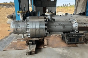
A double pipe heat exchanger is a simple device used to transfer heat between two liquids without letting them mix. It consists of one pipe placed inside a larger pipe. One fluid flows through the inner pipe while another flows through the outer pipe, allowing heat to pass through the metal wall separating them.
That structural simplicity delivers three capabilities no other design matches simultaneously: true counterflow in a single pass (enabling temperature crosses impossible in most other designs), full bilateral mechanical cleaning access to both circuits from open pipe ends, and extreme pressure capability from the inherent strength of the pipe-in-pipe geometry.
Anatomy — Inner Pipe, Annulus, and Return Bends
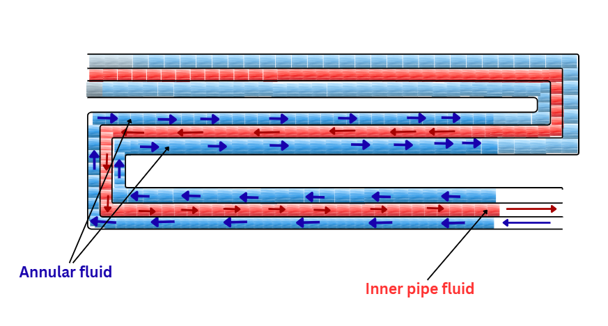
enters one end, exits the other
flows opposite direction (counterflow)
| Zone | Function | Key Engineering Note |
|---|---|---|
| Inner Pipe (Tube Side) | Contains the more corrosive, higher-pressure, or higher-viscosity fluid | Specified independently of the outer pipe — a carbon steel outer pipe can surround a Hastelloy inner pipe. Inner pipe wall thickness governs both pressure rating and conductive thermal resistance. |
| Annular Space (Shell Side) | Contains the second process fluid; narrow geometry drives high annular velocity | Annular gap width is a critical design parameter. Use hydraulic diameter D_h = D_outer(ID) − D_inner(OD) for all Reynolds number and Nusselt number calculations — using either pipe diameter alone is a common thermal design error. |
| Return Bends / Hairpin | U-shaped connections where fluids reverse direction; no heat transfer occurs here | Must withstand full operating pressure plus surge loads. For particulate or slurry service, use long-radius elbows to prevent solids accumulation. Bend material must match — never downgrade from — the connected pipe alloy specification. |
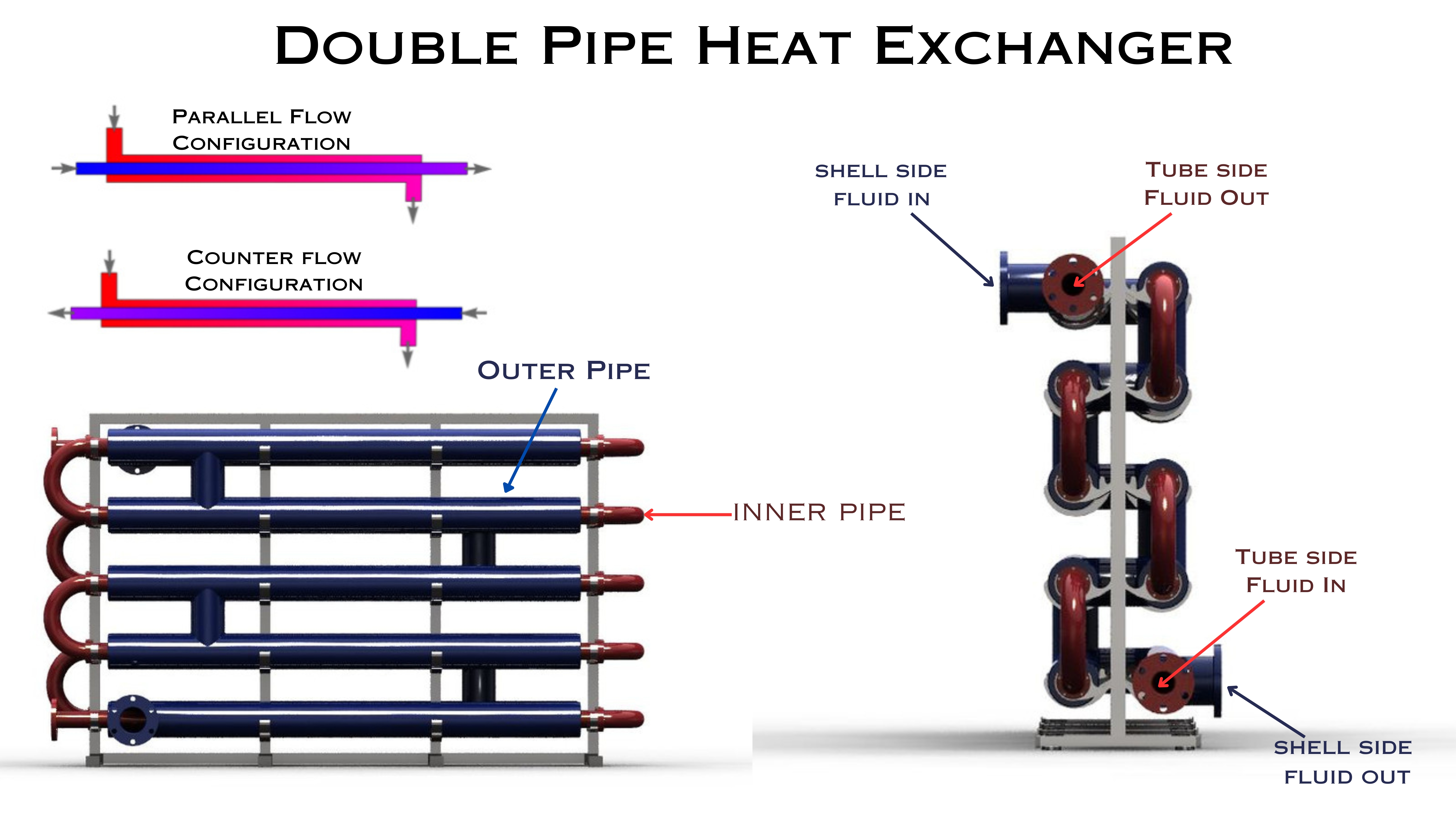
Counterflow vs. Parallel Flow — Why It Decides Everything
Flow direction is the single most important thermal design decision in a double pipe heat exchanger. It determines whether a temperature cross is achievable, how much surface area is required, and whether one unit or three shells in series can get the job done.
⇄ Counterflow — Always Specify This
Fluids travel in opposite directions60°F ← ← ← 200°F ← COLD
- Near-constant temperature driving force (ΔT) maintained along the full exchanger length
- Temperature cross achievable — cold outlet (200°F) exceeds hot outlet (160°F)
- LMTD correction factor F = 1.0 — no surface area penalty whatsoever
- Maximum heat recovery from a given area — the most thermally efficient arrangement possible
⇉ Parallel Flow — Limited Use Only
Fluids travel in the same directionCOLD → 60°F → → → 160°F
- ΔT is largest at the inlet and smallest at the outlet — thermally inefficient downstream
- Temperature cross is impossible — cold outlet can never exceed hot outlet
- Always requires more surface area than counterflow for identical terminal temperatures
- Specify only when rapid initial cooling or inlet-end piping constraints force it
Types of Double Pipe Heat Exchangers
Straight Single-Tube (Classic Double Pipe)
A single inner pipe inside a straight outer pipe. Sections 6–20 ft long are connected in series by external return bends to build up heat transfer area. Both fluid connections are at opposite ends.
- Heat transfer area: 1–15 ft² per section
- Ideal for pilot plants, lab-scale processes, and duties below 50 kW
- Full cleaning access: disconnect return bends, rod or hydro-blast both circuits from the open ends
Hairpin Heat Exchanger (Multi-Tube, U-Bent)
Multiple inner tubes (2–20) inside the outer pipe, bent into a U-shape so both inlet and outlet connections are at the same end. Multiple hairpin sections stacked in series reach 10–200+ ft² of total area. This is the industrial-scale standard for viscous, fouling, and temperature-cross services.
- Modular: add or remove sections to adjust capacity over plant life without replacing the unit
- Thermal expansion is inherent — the U-bend end floats freely, no expansion joint required
- Clean from the fixed head end: open once, all tubes and annular space are simultaneously accessible
- Best for: viscous fluids (>50 cP), high-fouling services, 50 kW–2 MW heat duties
Straight Multi-Tube Double Pipe
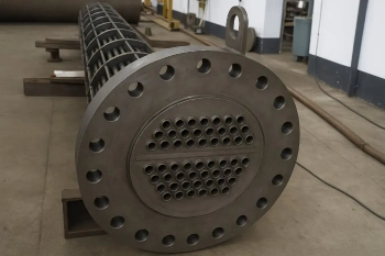
Multiple inner tubes in a straight (non-U-bent) outer pipe with separate inlet and outlet connections at each end. Bridges the gap between a simple double pipe and a full shell-and-tube — more area per unit length, with straight-through bilateral cleaning access from both ends.
- Higher tube-side velocity for a given total flow rate than a single large inner tube
- Both ends physically open for rods, brushes, or hydro-blast lances
- Best for services requiring both high heat transfer area and bilateral straight-through cleaning access
Jacketed Pipe (Transfer Line Heater / Cooler)
The double-pipe concept applied to process transfer lines — a process pipe surrounded by a jacket pipe carrying heating or cooling medium. The line simultaneously transports and thermally conditions the process fluid in transit.
- Maintains process temperature during transfer to prevent crystallization, viscosity increase, or thermal degradation
- Common in pharmaceutical API transfer lines, food processing piping, and chemical plant headers
- Designed per ASME B31.3 (piping code) when the transport function is primary
8 Advantages That Make It the Right Choice
True Counterflow — F = 1.0
No LMTD correction factor. Every square foot of surface operates at maximum thermodynamic efficiency.
Temperature Cross in One Pass
Cold outlet exceeds hot outlet — achieved in a single section. Requires multiple shells in series with shell-and-tube.
Extreme Pressure Capability
Pipe geometry routinely handles 5,000 psi. Designed to 10,000+ psi in small diameters without custom pressure vessel shells.
Full Bilateral Cleaning Access
Open either end — both circuits are accessible for rods, brushes, or hydro-blast lances. No bundle to pull.
High Annular Velocity
Narrow annulus produces 3–4× higher velocity than the same flow in a larger pipe, promoting turbulence in viscous fluids.
Independent Material per Circuit
Inner pipe in Hastelloy; outer pipe in carbon steel. Full alloy optimization without compromising containment integrity.
Inherent Thermal Expansion
Hairpin U-bend floats freely — no expansion joint, no floating head, no thermal stress analysis of connections required.
Modular and Expandable
Add sections in series or parallel as production rates change. No other exchanger type offers this level of operational flexibility.
Limitations — When to Choose Something Else
| Limitation | Why It Matters | Specify Instead |
|---|---|---|
| Low area per unit volume | A single-tube section provides only 0.2–2.0 ft²/linear ft. Above 2–3 MW, section lengths become impractical for most plant layouts. | Shell-and-tube for large duties requiring compact layout |
| High capital cost per ft² of area | Pipe + fittings + return bends + connections accumulate cost. Economy of scale reverses above ~1 MW compared to tube bundle fabrication. | Shell-and-tube above ~1 MW where per-area cost dominates the decision |
| Very high flow rates on both sides | The narrow annular space that creates high velocity also generates high pressure drop at elevated flow rates. Both-side high-flow scenarios can exceed allowable ΔP before adequate area is reached. | Baffled shell-and-tube for high-flow applications needing independent pressure drop control |
| Clean, low-viscosity, high-flow duties | Water or light hydrocarbons at high flow rates achieve turbulence easily in any geometry — the annular velocity advantage is irrelevant and the higher per-area cost unjustified. | Shell-and-tube or plate heat exchanger |
Double Pipe vs. Shell-and-Tube vs. Plate — Decision Table
| Attribute | Double Pipe / Hairpin | Shell-and-Tube | Plate |
|---|---|---|---|
| True Counterflow | Pure, single pass | Partial — multi-pass LMTD correction required | Near-pure |
| Temperature Cross | Single section | Multiple shells in series only | Single frame |
| Max Pressure | 10,000+ psi | Up to 5,000+ psi | Typically <300 psi |
| Viscous Fluid Performance | Excellent — annular turbulence | Good with baffles | Excellent — corrugated plates |
| Bilateral Mechanical Cleaning | Both circuits from open ends | Tube side only (fixed TS); shell with floating head | Plate-by-plate |
| Area per Unit Volume | Low | Moderate | High |
| Economy of Scale | Best <1 MW | Best >1 MW | Competitive for clean liquid-liquid |
| Thermal Expansion | Inherent in hairpin | Requires floating head or expansion joint | Plates flex |
Industrial Applications
| Industry | Typical Service | Why Double Pipe Is Specified |
|---|---|---|
| Chemical Processing | Viscous polymer precursor coolers, resin product coolers, solvent-to-solvent heat recovery | Annular turbulence for high viscosity; temperature cross in solvent recovery; pipe geometry strength for high-pressure reactor feeds |
| Pharmaceutical | API solution heating and cooling, solvent recovery condensers, crystallization temperature control | cGMP bilateral cleaning access; 316L SS electropolished inner pipe; PTFE gaskets; full material traceability documentation |
| Food & Beverage | Honey, molasses, glucose syrup, chocolate, fruit concentrate, tomato paste heating and cooling | High annular velocity reduces fouling on viscous products; full CIP validation; FDA-compliant materials with Ra <0.8 µm finish |
| Oil & Gas / Refining | Heavy fuel oil coolers, bitumen and asphaltene handling, high-pressure H₂-rich stream exchangers | Very high pressure H₂ services (>3,000 psi) suit pipe geometry; high velocity prevents heavy oil and bitumen deposition |
| Polymer & Rubber | Molten polymer coolers, polyol solution temperature control, adhesive solution coolers | Multi-tube hairpin maintains turbulence in 500–10,000 cP materials; heated outer pipe jacket keeps product flowing at operating temperature |
| Pilot Plants & R&D | All heat exchange duties in experimental and process development loops | Modular sections adjustable between test runs; easy disassembly for material or geometry comparison; small footprint suits lab space |
Maintenance — The Cleaning Advantage Explained
Performance Monitoring — When to Clean
- Rising outlet temperature at constant inlet conditions and flow rate — the earliest and most sensitive fouling indicator. A sustained 3–5°F rise over 30 days is an actionable signal to schedule cleaning before performance degradation becomes severe.
- Rising differential pressure on either circuit — even a thin deposit layer in the annular space causes a disproportionate pressure drop increase due to the small hydraulic diameter. Monitor DP on both circuits independently.
- U-value decline of 20% from the clean baseline — the standard cleaning trigger for most process services. Calculate U from current process data at each monitoring interval and trend against the design value.
Tube-Side Cleaning
Open the channel head at the fixed-end connection (hairpin) or disconnect the return bend (straight sections). All inner tube inlets are simultaneously exposed. Insert cleaning rod, brush, or hydro-blast lance and work the full tube length. For aseptic, cryogenic, or high-pressure gas services where mechanical tool access is impractical, circulate chemical cleaning solution — organic acid for scale, alkaline for organic deposits, enzymatic cleaner for biological fouling in food and pharma applications.
Annular-Side Cleaning
Disconnect the outer pipe section at either end. High-pressure water lance directed through the annular space dislodges scale and soft deposits from the inner pipe outer surface — the most common fouling location on the annular side. For hard scale (calcium carbonate, silicate), chemical soak is more effective — fill the annular space, hold the recommended dwell time, then flush at high velocity with clean water.
At-Disassembly Inspection
- Visual inspection of inner pipe outer surface for pitting, uniform corrosion, and erosion at return bend entry points — highest velocity zone, most mechanical wear
- Ultrasonic thickness measurement (UTM) of inner pipe wall at known corrosion-risk locations; track remaining wall versus the minimum required thickness
- Replace all gaskets at every disassembly — gasket reuse is the leading cause of post-maintenance flange leaks in double pipe systems
- Verify sliding supports are free to move — seized supports concentrate thermal expansion stress at the fixed-end connections and can cause fatigue cracking
Applicable Standards and Codes
| Standard | Scope | How It Applies to Double Pipe Exchangers |
|---|---|---|
| ASME BPVC Sec. VIII Div. 1 & 2 | Pressure vessel design, fabrication, and U-Stamp certification | Applies when operating pressure exceeds 15 psi and the unit is classified as a pressure vessel. Header end closures, return bend assemblies, and manifolds all fall under Section VIII jurisdiction. |
| ASME B31.3 | Process piping design and fabrication | Governs jacketed pipe transfer lines and single-section designs classified as piping rather than pressure vessels. |
| ASME Section IX | Welding procedure and welder qualification | All pressure-containing welds — inner pipe seam welds, end closure welds, return bend attachment welds, and flange welds — regardless of vessel vs. piping classification. |
| TEMA Class R / B / C | Heat exchanger fabrication tolerances and fouling factors | Class R for refinery service (most stringent), Class B for chemical process, Class C for general commercial. TEMA also governs standard fouling resistance values used in thermal design. |
| API 660 | Heat exchangers for petroleum, petrochemical, and natural gas | When specified, adds nozzle load, vibration analysis, enhanced NDE, test pressures, and documentation requirements beyond the TEMA/ASME baseline. |
| NACE MR0175 / ISO 15156 | Material qualification for H₂S sour service | Governs maximum hardness of all wetted components. PWHT of carbon steel welds is mandatory in most sour-service double pipe applications. |
| ASME B16.5 | Pipe flange pressure-temperature ratings | Sets flange class (150# to 2500#) based on pipe material, design pressure, and design temperature for all inlet and outlet nozzles. |
Frequently Asked Questions
What is a double pipe heat exchanger?
A double pipe heat exchanger is one pipe placed concentrically inside a larger outer pipe. One fluid flows through the inner pipe; the second flows through the annular space between the pipes. Heat transfers through the inner pipe wall. Its defining advantages are true counterflow in a single pass, extreme pressure capability, and full mechanical cleaning access to both circuits from open pipe ends.
What is the difference between a double pipe and a hairpin heat exchanger?
A double pipe exchanger is a single straight pipe-in-pipe section. A hairpin exchanger is the multi-tube, U-bent version — multiple inner tubes in the same outer pipe, bent so both connections are at the same end, with multiple sections stacked in series for larger area. Hairpins provide far more heat transfer area per floor space while retaining all the cleaning and thermal expansion advantages of the pipe-in-pipe geometry.
Why is counterflow so important in a double pipe heat exchanger?
In counterflow, both fluids travel in opposite directions — maintaining a nearly constant temperature driving force along the full length and enabling a temperature cross (cold outlet exceeds hot outlet), which is thermodynamically impossible in parallel flow. For the same heat duty and terminal temperatures, counterflow requires 30–50% less surface area than parallel flow. Specify counterflow unless there is a specific process reason not to.
Can a double pipe heat exchanger handle a temperature cross?
Yes — and this is its most decisive advantage. In true counterflow, the cold fluid outlet temperature can exceed the hot fluid outlet temperature in a single pass. Achieving this in a shell-and-tube requires multiple shells in series with corresponding increases in cost and plot space. For temperature-cross duties, double pipe is typically the simplest, most economical solution available.
Why is it preferred for viscous fluids?
The narrow annular space creates velocities 3–4× higher than the same fluid at the same flow rate through a larger pipe. Higher velocity promotes turbulence in fluids that would be laminar elsewhere, increases the convective heat transfer coefficient, and provides self-cleaning behavior at the heat transfer surface. For fluids above ~50 cP — heavy oils, resins, food pastes, polymer solutions — this makes the double pipe exchanger thermally superior to a shell-and-tube of comparable size.
What information do I need to get a quote?
Both fluid names and compositions; flow rates for both streams; inlet and outlet temperatures; operating and design pressures; fluid viscosities at operating temperature; allowable pressure drop on both sides; fouling tendency; applicable design code (ASME Sec. VIII, B31.3, TEMA, API 660); any material preferences or corrosion constraints; and available space envelope. Our engineering team returns a fully itemized budgetary proposal within 48 hours.
Are United Heat Exchangers units ASME certified?
Yes. All pressure-containing assemblies are fabricated per ASME BPVC Section VIII Division 1 (pressure vessel classification) or ASME B31.3 (piping classification) as determined by the project specification. United Heat Exchangers holds current ASME U-Stamp and R-Stamp certifications. All welding is performed under procedures qualified per ASME Section IX. We also comply with TEMA, API 660, NACE MR0175, PED 2014/68/EU, IS 2825, and other applicable codes.
Get a Free Quote in 48 Hours
Share your fluid data, flow rates, temperatures, pressures, viscosity, fouling tendency, and applicable codes. Our engineering team will specify the right single-tube or multi-tube hairpin configuration, complete the thermal design, and deliver a fully itemized proposal — no obligation.
Request My Free Quote →Author: Gowtham, Technical Director — United Heat Exchangers Pvt. Ltd. | Published: March 2026 | Related: Hairpin Heat Exchanger | Shell and Tube | Plate Heat Exchanger
Related Products