Author: Senthil Kumar, Technical Director | Updated: June 2026
Table of Contents
- What Is a Furnace Cooler?
- Why Furnace Cooling Is Essential
- How a Furnace Cooler Works
- Types of Furnace Coolers
- Furnace Cooler Anatomy — Key Components
- Engineering Advantages
- Design Specifications and Standards
- Material Selection
- Industries and Applications
- How to Select a Furnace Cooler
- Why United Heat Exchangers
- Delivery and What's Included
- Frequently Asked Questions
What Is a Furnace Cooler?
A furnace cooler is a water-cooled heat transfer assembly installed on, in, or around an industrial furnace to protect its structural components, refractory linings, mechanical systems, and process instrumentation from the extreme radiant and convective heat generated inside the furnace chamber. Industrial furnaces — particularly electric arc furnaces (EAF) in steelmaking, blast furnaces in ironmaking, cupola furnaces in foundries, and high-temperature industrial heating furnaces — operate at internal temperatures of 1,400–1,800°C, generating radiant heat fluxes of 150–600 kW/m² at the furnace wall. Without active cooling, structural steel and mechanical components exposed to this radiation would fail within minutes.
A furnace cooling system circulates pressurized cooling water through hollow panels, tubes, jackets, or fabricated sections that are positioned at the furnace hot face. The cooling water absorbs the radiant heat load conducted through or radiated onto the cooled component, keeping metal surface temperatures well below the critical threshold — typically below 200°C for carbon steel — at which rapid oxidation, thermal deformation, and structural failure would begin. The heated water then returns to a cooling tower or heat exchanger where its heat is rejected before recirculation.
As a trusted furnace cooler manufacturer in India, United Heat Exchangers designs and fabricates water cooled furnace panels, furnace door coolers, electrode arm coolers, furnace roof delta coolers, tuyere coolers, and furnace fume hood coolers for electric arc furnaces, blast furnaces, induction furnaces, and industrial heating furnaces — all in carbon steel, with stainless and alloy options for aggressive furnace environments.
Why Furnace Cooling Is Essential
The case for active water cooling on furnace components is not a design preference — it is a physical necessity dictated by the thermal limits of the structural and mechanical materials that furnace shells, doors, electrode arms, and roofs are made from.
Structural Integrity of the Furnace Shell
Carbon steel begins to lose significant yield strength above 300°C and undergoes rapid oxidation above 500°C. In a steelmaking EAF, the radiant heat flux at the upper sidewall easily exceeds 200 kW/m² — sufficient to raise an uncooled steel panel to failure temperature within a single heat. Water cooled panels keep the steel at 60–150°C throughout the production campaign.
Extension of Refractory Campaign Life
Furnace refractory linings erode and wear progressively in service. Water cooled stave panels and splash coolers on the EAF sidewall allow a protective skull of solidified slag to form on the cooled surface — this slag skull effectively becomes a self-renewing refractory lining that dramatically extends the campaign between full refractory relining shutdowns.
Protection of Mechanical Systems
Electrode arms, clamps, cable connectors, and furnace tilting mechanisms are all mechanical assemblies that operate close to the furnace hot zone. Uncontrolled heat radiation into these components causes thermal expansion mismatch, seizure of sliding surfaces, and degradation of electrical insulation — active cooling is mandatory for reliable long-term operation of these systems.
Prevention of Furnace Breakout
In the most severe consequence scenario, a failed or inadequately cooled furnace panel exposed to the full EAF radiant flux can reach the melting point of the panel wall, creating a hole through which liquid steel or slag escapes — a furnace breakout. Active furnace cooling with flow monitoring and temperature alarms is the primary safeguard against this catastrophic and life-threatening event.
Energy Recovery Opportunity
The heat absorbed by furnace cooling water systems in a large steelmaking EAF or blast furnace stave cooling system represents a substantial energy stream — typically 80–150 kWh per ton of steel produced. Modern waste heat recovery systems capture this heat to generate steam for plant use or to preheat scrap or combustion air, improving the overall energy efficiency of the steelmaking facility.
Reduced Maintenance Downtime
The frequency and length of furnace maintenance shutdowns, which are the main factor limiting production capacity in EAF and blast furnace operations, are reduced when properly cooled furnace components last much longer between replacement cycles. The capital cost of a comprehensive furnace cooling system is recovered many times over in the additional campaign tons produced between relining shutdowns.
How a Furnace Cooler Works
Every furnace cooler, regardless of its specific geometry or position in the furnace, operates on the same fundamental principle: cooling water is circulated through a hollow metal structure positioned at the furnace hot face, absorbs the radiant and conductive heat flux through the cooled metal surface, and is discharged at elevated temperature to an external cooling system. The heat transfer path is: furnace radiation → furnace-facing metal surface → conduction through panel wall → convection to flowing cooling water → external heat rejection.
Engineering Insight — Skull Formation on Cooled Panels: One of the most valuable thermal phenomena in EAF and blast furnace cooling is the formation of a skull — a solidified layer of slag or freeze lining that builds up on the cold face of the furnace cooling panel. When the panel surface temperature is maintained well below the slag solidification point (typically 1,100–1,250°C for blast furnace slag), incoming liquid slag that contacts the cooled surface freezes solid against it. This frozen skull layer performs two functions simultaneously: it acts as a thermal insulator between the furnace interior and the panel wall (dramatically reducing the heat flux that the cooling water must absorb), and it provides a self-renewing refractory lining that protects the panel from slag erosion and chemical attack. The design of effective furnace stave coolers is fundamentally about providing exactly the right surface temperature to promote and maintain a stable freeze lining — cool enough to solidify the slag but not so cold that the skull grows uncontrollably thick and restricts the furnace working volume.
Types of Furnace Coolers
Water Cooled Furnace Wall Panels
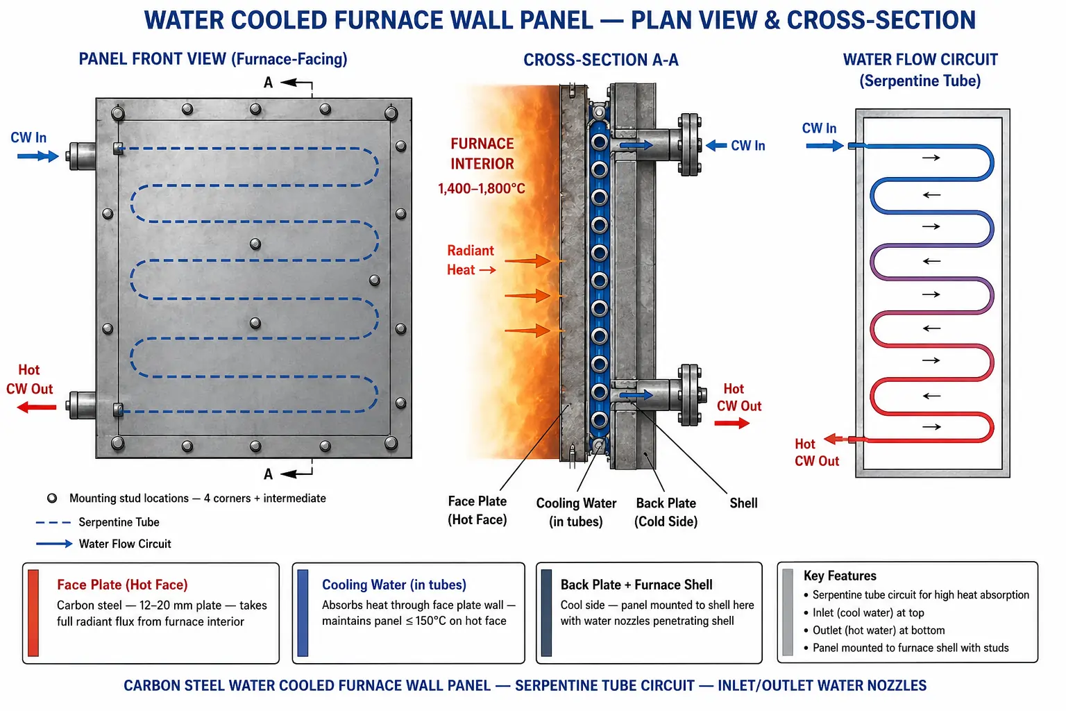
Flat or curved panel assemblies — EAF upper sidewall and hot spot protectionFabricated carbon steel panels with internal water flow channels — typically a grid of seamless steel tubes welded to a flat face plate, or a plate-and-channel construction — mounted on the upper sidewall of an EAF above the refractory working lining. The panels absorb the direct radiant heat flux from the electric arc and the hot steel bath.
- Flat panel for straight sidewall sections; curved panel for circular furnace geometry
- Internal serpentine or parallel tube flow circuits for uniform water distribution
- Inlet and outlet water nozzles matched to the furnace cooling water supply header
- Mounting studs and alignment features for precise positioning in the furnace shell
- Designed for rapid changeout during short furnace maintenance windows
Furnace Door Cooler
Water-jacketed door frame, sill, and lintel — EAF and industrial furnace doorsWater-cooled frames, sills, and lintels surrounding the charging door, tap hole, and maintenance access openings of electric arc furnaces and high-temperature industrial furnaces. The door opening is the most vulnerable area of the furnace shell — direct radiation exposure during charging and tapping operations demands robust, continuously cooled protection.
- Box section or tube-fabricated water-cooled door frame — full perimeter cooling
- Sill cooler protects the door threshold from liquid steel and slag splash
- Lintel cooler protects the top beam of the charging door opening
- Matched to existing door frame dimensions for direct bolt-on replacement
- High-flow design for areas with peak heat flux during furnace charging
Electrode Arm Cooler
Hollow water-cooled electrode arms — EAF graphite electrode supportThe electrode arms of an electric arc furnace support and position the graphite electrodes, which carry up to 100 kA of current and operate within meters of the electric arc at temperatures above 1,600°C. The arms are hollow structural members through which cooling water circulates continuously — without this cooling, the arm would rapidly deform from thermal stress and electrical heating from induced eddy currents.
- Hollow fabricated carbon steel arm with internal cooling water passages
- Insulated water-in and water-out connections — electrical isolation maintained between the cooling circuit and furnace electrical system
- High water velocity through the arm to maximize heat removal from the electrode clamping zone
- Matched to existing EAF electrode arm mechanical interface dimensions
- Flow monitoring on each arm for early detection of internal blockage or failure
Furnace Roof Cooler (Delta Panel)
Water-cooled delta sections and center ring — EAF roof assemblyThe roof of an electric arc furnace is constructed from water-cooled delta sections — triangular or trapezoidal fabricated steel panels with internal water channels — assembled around a central refractory-filled roof ring. The roof coolers absorb the upward radiation from the electric arc and the hot steel bath, preventing the roof structure from overheating during the melt-down and refining periods.
- Delta section panels fabricated to match the arc furnace roof cone angle and radius
- Centre ring cooler protects the refractory dome section around the electrode openings
- Roof lift and swing mechanism connections accommodated in the cooler design
- Internal channels that are sized for sufficient water velocity to avoid the formation of steam during peak flux
- Quick-disconnect water couplings for rapid roof removal during electrode changes
Blast Furnace Stave Cooler
Copper or cast iron stave — blast furnace wall campaign extensionStave coolers are cast iron or fabricated copper cooling elements installed inside the blast furnace shell at the belly, bosh, and stack zones. Each stave is a large, flat or curved panel with embedded cooling water channels, mounted directly against the furnace shell. Their primary function is to maintain the freeze lining of solidified burden material that protects the furnace shell from the 1,500–1,600°C hot blast and burden.
- Cast iron staves for standard service; copper staves for maximum heat extraction and longest campaign
- Embedded cooling channel geometry optimized for uniform surface temperature and skull stability
- External water connection headers machined into the stave body
- Stack staves cooled at lower heat flux; belly and bosh staves designed for peak thermal duty
- Campaign life target: 10–20 years for modern copper stave designs in well-operated blast furnaces
Furnace Fume Hood Cooler
Water-cooled fume extraction hood — EAF and smelting furnace off-gasThe fume extraction hood positioned above the electric arc furnace or smelting furnace is exposed to intense radiant heat from the open furnace roof during charging and the direct discharge of high-temperature off-gas (1,000–1,400°C) during the melt-down period. Water cooled hood panels protect the structural steel hood from the off-gas thermal load while ensuring the fume extraction ductwork remains serviceable over a full production campaign.
- Curved panel sections matching the hood geometry — full circumferential water cooling
- Off-gas duct entry transition cooled where gas temperature is highest
- Carbon steel construction — stainless or alloy cladding on the gas-contact face for corrosion resistance
- Integrated soot and fume collection lips at the hood perimeter
- Flanged inlet and outlet water connections with flow and temperature monitoring provisions
Furnace Cooler Anatomy — Key Components
Hot Face Plate
The furnace-facing surface of the cooler — a carbon steel plate 10–25 mm thick that absorbs direct radiant heat from the furnace interior. Surface temperature is held below 150–200°C by the cooling water flowing behind it. The hot face may be grit-blasted and left bare to encourage slag skull formation, or clad with a ceramic or refractory layer in specific zones.
Cooling Water Circuit
Seamless carbon steel tubes welded to the back of the face plate in a serpentine or parallel arrangement, carrying cooling water at 3–6 m/s to ensure turbulent flow and high heat transfer coefficient. Tube diameter and wall thickness are sized for the design working pressure — typically 6–12 bar for furnace cooling circuits.
Header Pipes and Inlet/Outlet Nozzles
The inlet distributor and outlet collection header connect the furnace cooling circuit to the plant cooling water supply system. Nozzle sizes and orientations are matched to the furnace cooling water manifold piping. Flanged connections (ASME B16.5 Class 150 or 300) for leak-free, maintenance-friendly assembly.
Mounting and Retention Hardware
Studs, lugs, and brackets welded to the furnace-facing plate allow the cooler to be bolted to the furnace shell structure. Mounting hardware is designed for rapid removal and reinstallation during the short furnace maintenance windows available between production heats.
Thermocouples and Flow Monitoring Provisions
Thermocouple pockets welded into the panel face plate and hot-water outlet nozzle enable continuous monitoring of panel metal temperature and cooling water outlet temperature — the primary early warning signals for a degrading or failing panel in service.
Vent and Drain Connections
Small-bore vent nozzles at the highest point of the cooling circuit allow complete air purging during initial fill-up — eliminating steam pockets that would disrupt cooling water flow distribution and create localized overheating in the panel.
Engineering Advantages of Water Cooled Furnace Systems
Dramatically Extended Furnace Campaign Life
Water cooled panels and stave coolers allow furnace campaigns to extend from weeks to months or even years by maintaining the structural integrity of the shell and promoting protective skull formation — directly increasing the tons produced per refractory shutdown.
Prevention of Catastrophic Failure
Active cooling with continuous flow monitoring and temperature alarms provides the earliest possible warning of panel failure — allowing controlled furnace shutdown before a breakout event that would cause liquid steel or slag release, equipment destruction, and serious injury risk.
Reduced Refractory Consumption
Cooled upper sidewalls in EAF allow thinner refractory lining in the cooled zone — in some designs, the cooled panel itself replaces the upper sidewall refractory entirely — reducing both the volume of expensive refractory consumed and the time required for relining.
Higher Power-On Time in EAF Operations
Robust furnace cooling enables the arc furnace to run at higher power input levels without overheating the sidewall panels — increasing melt rates, reducing tap-to-tap time, and improving the productivity of the furnace in tons per hour.
Waste Heat Recovery Potential
The hot cooling water leaving furnace panels carries substantial recoverable heat — in large EAF operations, waste heat recovery from the cooling circuit generates steam for plant use, improving overall energy efficiency and reducing operating cost.
Rapid Changeout and Standardized Replacement
Custom-fabricated furnace coolers matched exactly to the existing furnace geometry can be pre-positioned at the furnace and swapped out within a planned maintenance window — minimizing production losses during panel replacement.
Design Specifications and Standards
Furnace Cooler — Standard Design Parameters (United Heat Exchangers)
Material Selection
The selection of materials for a furnace cooler balances four competing requirements: adequate strength at the operating panel temperature under cooling water pressure; good weldability for fabrication of complex panel geometry; resistance to the furnace-side chemical environment (oxidation, slag chemical attack, acid fume condensate); and cost.
| Material | Application | Key Advantage |
|---|---|---|
| Carbon Steel A36 / IS 2062 | Standard EAF panels, door coolers, roof delta panels, fume hoods | Most cost-effective, excellent weldability, adequate strength below 300°C with cooling |
| SA-179 Seamless CS Tube | Internal cooling water tubes in all panel types | Seamless construction — no weld seam in the pressurized cooling tube circuit; reliable pressure containment |
| 316L Stainless Steel | Hot face cladding for acid fume environments; fume hood coolers | Superior oxidation and acid corrosion resistance where furnace off-gas is aggressive |
| Cast Iron | Blast furnace stave coolers (lower cost option) | Good thermal conductivity vs cost; established track record in BF stave cooling |
| Pure Copper | Blast furnace copper stave coolers (high-performance) | Highest thermal conductivity of any structural metal — maximises freeze lining stability and campaign life |
Industries and Applications
| Furnace Type | Furnace Cooler Type | Operating Conditions |
|---|---|---|
| Electric Arc Furnace (EAF) | Wall panels, door sill coolers, roof delta panels, electrode arm coolers, fume hood coolers | Arc temperatures to 3,500°C; steel bath at 1,600°C; sidewall radiant flux 150–500 kW/m² |
| Blast Furnace | Copper or cast iron stave coolers, tuyere coolers, hot blast valve coolers | Raceway temperatures to 2,000°C; hot blast at 1,000–1,200°C; continuous 24/7 operation |
| Cupola Furnace | Water-jacketed shell panels, tuyere plate coolers | Iron melting at 1,400–1,500°C; coke combustion zones to 1,900°C |
| Ferroalloy Submerged Arc Furnace | Electrode clamp coolers, furnace shell panels, tap hole area coolers | Operating temperatures to 1,700°C; aggressive slag chemistry; continuous service |
| Non-Ferrous Smelting (Copper, Nickel) | Sidewall panels, off-gas hood coolers, tap hole frame coolers | Flash smelter temperatures to 1,500°C; SO₂-rich aggressive gas environment |
| Industrial Heating Furnace | Door frame coolers, hearth support water cooled beams, skid rails | Furnace atmosphere to 1,300°C; continuous cycling with charge/discharge cycles |
How to Select a Furnace Cooler
Identify the Furnace Type and Zone
Specify your furnace type (EAF, blast furnace, cupola, induction), the specific zone to be cooled (sidewall, door, roof, electrode arm), and the furnace geometric dimensions for that zone — furnace coolers are custom fabricated to match your exact furnace layout.
Define the Heat Flux and Temperature
Provide the furnace operating temperature and the estimated or measured radiant heat flux at the panel location — this governs tube spacing, tube diameter, water flow velocity, and panel plate thickness to keep metal temperatures within acceptable limits.
Confirm Cooling Water Parameters
Specify available cooling water pressure, supply temperature, maximum allowable return temperature, and water quality — these parameters set the design water-side pressure rating, flow circuit design, and tube material selection.
Provide Existing Panel Drawings
If replacing existing furnace coolers, supply the original fabrication drawings or measured dimensions — including mounting hole pattern, nozzle positions, and connection interfaces — so the replacement can be manufactured as a direct drop-in fit.
Specify Instrumentation Requirements
Confirm whether thermocouple pockets, flow monitoring tap connections, or other instrumentation provisions are needed — these are incorporated during fabrication and cannot be easily added to a finished panel without pressure re-testing.
Define Furnace Atmosphere Chemistry
For non-standard furnace atmospheres — high SO₂ for copper or nickel smelting, HCl-bearing gases in waste-to-energy furnaces — the furnace-facing material may need to be upgraded from plain carbon steel to a stainless or alloy cladding to resist hot corrosion at the panel hot face.
Why United Heat Exchangers
Exact-Fit Custom Fabrication
Every furnace cooler we fabricate is custom-designed and manufactured to your exact furnace dimensions — panel size, tube circuit geometry, nozzle positions, and mounting hardware — from your drawings or field measurements. No adaptor plates or compromises.
Hydrostatic Tested Before Dispatch
Every furnace cooler leaves our factory having passed a hydrostatic pressure test at 1.5× the design working pressure — the primary assurance that the cooling water circuit is sound before the panel enters the hot furnace environment.
Thermal Design Support
Our engineers review your furnace heat flux data and cooling water parameters to verify that the proposed panel design keeps metal temperatures within safe limits — providing a thermal confirmation alongside the fabrication drawing before manufacture begins.
All Furnace Cooler Types
Wall panels, door coolers, electrode arm coolers, roof delta panels, stave coolers, tuyere coolers, and fume hood coolers — all fabricated in carbon steel, stainless, or alloy as required — from a single specialist manufacturer.
Fast Delivery for Emergency Replacement
Panel failures in operating furnaces require fast replacement to minimize production loss. We maintain emergency fabrication capacity and stock common raw material for priority furnace cooler orders — contact us with your dimensions for a fast-track delivery assessment.
Full Documentation Package
Material certifications, hydrostatic test records, certified fabrication drawing, and dimensional inspection report issued with every furnace cooler — providing the traceability record required by plant quality management and insurance inspection regimes.
Request a Free Furnace Cooler Quote Within 48 Hours
Share your furnace type, zone to be cooled, panel dimensions or existing drawing, cooling water pressure and temperature, and any replacement or upgrade requirement. Our team will prepare a complete technical and commercial proposal within 48 hours — including thermal review, material recommendation, and hydrostatic test specification.
Request My Free Quote →Delivery and What's Included
What's Included with Every Furnace Cooler Order
- Custom fabrication to your exact dimensions — panel geometry, tube circuit layout, nozzle positions, and mounting hardware matched to your furnace drawing or field-measured dimensions
- Thermal review — confirmation that the panel tube spacing and water flow velocity maintains metal temperatures within safe limits at the specified heat flux and cooling water conditions
- Material certifications (MTRs) — traceable mill test reports for all pressure-containing materials: face plate, tube, header pipe, and nozzle flanges
- Hydrostatic test certificate — each panel hydrotested at 1.5× design working pressure; leakage and pressure hold recorded and certified before dispatch
- Dimensional inspection report — key dimensions verified against the approved fabrication drawing and recorded as an acceptance document
- Certified fabrication drawing — as-built general arrangement drawing showing all dimensions, nozzle schedule, tube circuit routing, and mounting details; issued as a controlled document for plant records
- Installation and commissioning notes — cooling water flow direction, initial fill and vent procedure, thermocouple calibration check, and recommended flow rate range for the specific panel
Frequently Asked Questions — Furnace Coolers
What is a furnace cooler?
A furnace cooler is a water-cooled heat transfer component installed on or within an industrial furnace to protect structural elements, refractory linings, and critical mechanical parts from the extreme radiant and convective heat generated inside the furnace. Furnace coolers circulate cooling water through hollow panels, jackets, pipes, or fabricated sections to absorb radiant heat flux from the furnace interior, keeping metal temperatures within safe service limits and extending furnace campaign life between relining shutdowns.
What types of furnace coolers are available?
The main types of furnace coolers include water cooled furnace wall panels for EAF upper sidewall protection, furnace door coolers for charging and tap hole openings, electrode arm coolers for EAF graphite electrode support structures, furnace roof delta panels for EAF roof assemblies, blast furnace stave coolers in cast iron or copper, tuyere coolers for blast furnace air injection tuyeres, and furnace fume hood coolers for off-gas extraction systems above EAF and smelting furnaces.
Why is water cooling necessary for furnace components?
Industrial furnaces — particularly electric arc furnaces and blast furnaces — operate at internal temperatures of 1,400–1,800°C, generating radiant heat fluxes of 150–600 kW/m² at the furnace wall. Without active water cooling, structural steel would reach failure temperature within minutes. Water cooled furnace panels keep metal surface temperatures below 200°C, protecting the furnace shell, electrode systems, and mechanical drives throughout the production campaign and promoting the formation of a protective slag skull on the cooled surface that extends refractory campaign life.
What material is used to fabricate furnace coolers?
The majority of furnace coolers are fabricated from carbon steel — structural steel plate for the face plate and back plate, and seamless carbon steel tube (SA-179) for the internal cooling water circuit. Carbon steel is adequate because water cooling maintains the panel metal temperature well below the 300°C limit at which carbon steel begins to lose significant strength. For furnaces with aggressive off-gas chemistry — high SO₂ in copper smelting, or HCl in waste-to-energy furnaces — the hot face may be clad with 316L stainless steel or coated for improved oxidation and acid corrosion resistance.
How long does a furnace cooler last in service?
Service life of a furnace cooler panel depends on the furnace type, operating conditions, water quality, and the care taken in panel installation and operation. In a well-designed and correctly operated EAF, carbon steel wall panels typically last 6–18 months before replacement. Blast furnace copper stave coolers are designed for campaign lives of 10–20 years in modern well-operated furnaces. The most common causes of premature panel failure are inadequate cooling water flow (causing localized overheating), mechanical damage during charging (steel scrap impact), and internal tube blockage from scale deposition in hard cooling water.
Can United Heat Exchangers manufacture replacement furnace cooler panels?
Yes — United Heat Exchangers specializes in the custom fabrication of replacement furnace cooler panels for all furnace types. If you have the original fabrication drawing, we manufacture a direct replacement to those dimensions. If the drawing is unavailable, we work from field measurements taken during your maintenance shutdown. Replacement panels are hydrotested at 1.5× working pressure and dispatch with full material certifications and a certified as-built drawing. Contact our team with your furnace type, panel dimensions, and required delivery date for a priority assessment.
Author: Senthil Kumar, Technical Director — United Heat Exchangers Pvt. Ltd. | Last Updated: June 2026