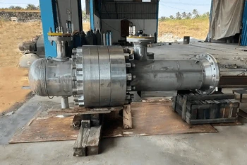
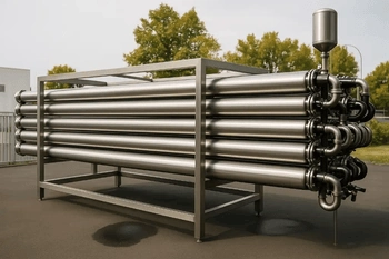
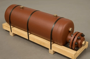
U Tube Heat Exchanger
Request a Quote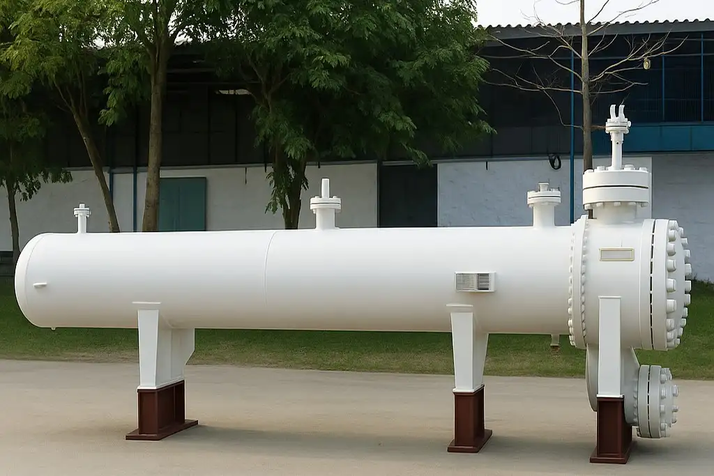
United Heat Exchangers, a leading U-Tube Heat Exchanger manufacturer and supplier in India, delivers compact, high-performance solutions for industrial and marine thermal applications. Our U-tube design ensures excellent heat transfer efficiency, superior thermal expansion handling, and reliable operation in high-pressure, high-temperature environments. Built using stainless steel, carbon steel, copper, and other corrosion-resistant alloys, these exchangers are ideal for petrochemical plants, marine cooling systems, power generation, and process industries.
What is a U-Tube Heat Exchanger?
A U-tube heat exchanger uses U-shaped tubes with a single tube sheet, allowing for thermal expansion and simpler construction. It’s commonly used in boilers and reboilers, though cleaning is more difficult than with straight-tube designs.Basic Construction
The anatomy of a U-tube heat exchanger revolves around several core components:- Shell: A cylindrical pressure vessel that houses the tube bundle, typically made from carbon steel for durability. It contains the secondary fluid and withstands operational pressures up to 1000 psi or more.
- U-shaped Tube Bundle: Comprising dozens to hundreds of seamless tubes (e.g., 3/4-inch diameter), bent precisely at 180 degrees to form the U. These tubes carry the primary fluid and are packed in a triangular or square pitch layout for optimal density.
- Single Tubesheet: A thick, forged plate (often 2-4 inches) to which all tube ends are welded or rolled, serving as the interface between tube-side and shell-side fluids.
- Baffles: Perforated plates spaced along the shell to direct shell-side flow perpendicular to the tubes, enhancing turbulence and heat transfer. Segmental baffles are common, cut to 25-50% of the shell diameter.
- Channel/Head: A removable bonnet or flanged cover on the tube side, providing access for fluid inlet/outlet and maintenance.
- End Cover: Seals the shell end opposite the tubesheet, often with a bolted flange for inspection.
- Nozzle Connections: Inlet and outlet ports for both fluids, strategically placed to minimize dead zones and ensure even distribution.
Why “U-Tube”?
The U-shape isn't arbitrary—it's a genius solution for thermal expansion. Metals expand and contract with temperature changes; in straight-tube exchangers, this can warp tubesheets or cause leaks. The U-bend acts like a flexible joint, absorbing axial expansion up to several inches without stress. This makes U-tubes ideal for applications with differentials exceeding 200°F, such as steam condensers or oil coolers, where fixed designs would fail prematurely.Working Principle
Fluid Flow Arrangement
U-tube heat exchangers typically use a counterflow arrangement to maximize LMTD and overall efficiency. High-pressure or corrosive fluids flow through the U-shaped tubes, entering one side and exiting the other, while the shell side carries lower-pressure, high-volume fluids like cooling water. Baffles guide the shell fluid across the tubes to enhance turbulence and heat transfer, allowing approach temperatures as low as 5°F for superior performance compared to parallel flow systems.Heat Transfer Mechanism
Heat transfer in a U-tube exchanger occurs through conduction across thin tube walls and convection on both the tube and shell sides. Baffles increase turbulence, raising the overall heat transfer coefficient to 200–800 BTU/hr-ft²-°F. The U-bend causes a slight velocity increase and pressure drop, which can be minimized with a smooth bend radius. Together, these factors ensure efficient heat exchange without mixing the fluids.Design Features and Engineering Considerations
Single Tube sheet Design
The hallmark single tube sheet reduces fabrication costs by 20-30% and eliminates gasketed joints prone to leaks. However, it limits tube-side access for cleaning, as the bundle isn't removable without shell disassembly—a trade-off for applications with clean fluids.Tube Bundle Layout
Tube pitch (1.25-1.5x OD) optimizes packing density—triangular layouts offer 20% more surface area than square. Materials like CuNi 90/10 (for marine corrosion resistance, k=25 W/m-K) or SS316L (for chemicals, pitting-resistant) are chosen per ASTM specs. Diameters from 1/2-1 inch and walls per ASME ensure burst pressures over 3000 psi.Shell-side Design
Baffles—segmental for cost-effectiveness, helical for reduced fouling, or disc-and-donut for uniform flow—space 0.2-1x shell ID apart. Shell diameters scale with duty, from 6-60 inches, often with longitudinal fins for compact marine installs.Thermal Expansion Management
The U-bend's flexibility compensates for differential expansion (α∆T L, where α is the coefficient), preventing tube-to-sheet fatigue. For 300°F swings, it handles 0.5-1 inch movement, making it superior for high-temp duties like flue gas coolers.Maintenance Design Factors
Tubes are straightenable for chemical cleaning, but bundles are semi-removable via flanged shells. Inspection ports and vent/drain nozzles facilitate borescope checks and hydro-testing.Types of U-Tube Heat Exchangers
According to Standards
Per TEMA (Tubular Exchanger Manufacturers Association), the UHX type features one tubesheet with U-tubes, compliant with ASME Section VIII. The "U" designation emphasizes the bend, ensuring interchangeability in retrofit projects.Based on Industry Usage
Marine versions prioritize compactness (e.g., box coolers for ships), petrochemical ones handle hydrocarbons at 500 psi, and HVAC chillers use them as evaporators for R-134a refrigeration cycles.Custom Configurations
Multi-pass (2-4) U-tubes increase LMTD via internal partitions; high-pressure variants use thick-walled titanium tubes for 2000 psi; compact designs shrink footprints by 40% with microchannel bundles for offshore platforms.Applications of U-Tube Heat Exchangers
Marine Industry
In ships, they cool engine jacket water from 180°F to 100°F using seawater, lube oils in turbines, and enable freshwater production via heat recovery from exhaust.Industrial Sectors
Petrochemical plants use them for distillate fractionation; power plants preheat boiler feedwater, recovering 80% waste heat; chemical systems manage exothermic reactions.HVAC and Refrigeration
Chillers employ U-tube condensers for water-cooled efficiency, handling 100-500 tons of cooling with minimal refrigerant charge.Renewable Energy
Geothermal loops transfer earth heat to working fluids; biomass boilers cool flue gases, reducing emissions.Advantages of U-Tube Heat Exchangers
U-tubes shine with unmatched thermal expansion tolerance, preventing failures in cyclic operations. Their counterflow yields 15-20% higher efficiency than straight tubes. Single tubesheet slashes costs by 25%, while handling 1000 psi differentials and 600°F temps. Compact (50% lighter than fixed heads) and versatile for hot fluids, they're a go-to for reliability.Limitations and Challenges
Cleaning the U-bend demands solvents over brushes, risking incomplete removal in fouled services. Tube swaps require bundle extraction, hiking downtime. They're suboptimal for slurries (fouling factor >0.002 hr-ft²-°F), and the bend adds 10-20% pressure drop, potentially needing larger pumps.Design Calculation Parameters
Thermal Design Inputs
Duty Q = m Cp ∆T guides sizing, with U from 150-600 BTU/hr-ft²-°F. Fouling (0.001-0.005) derates performance; LMTD correction F=0.9-1.0 for multipass.Mechanical Design Inputs
Shell ID per Do/t= allowable stress; tubes per t= P D / (2 S E + P); baffles at 12-24 inch spacing to limit vibrations (f< natural frequency).Standards and Codes
ASME VIII Div 1 mandates UG-27 for shells; TEMA Class R for refinery use; API 660 for process exchangers.Materials Used for U-Tube Heat Exchangers
Tube Materials
Copper (k=400 W/m-K, economical); CuNi 90/10 (ER<0.03 mpy in seawater); SS304/316 (Cl-resistant); Duplex (yield>60 ksi); Titanium (pitting >1000 mV, for brines).Shell Materials
Mild steel (cheap, weldable); carbon steel (ASME SA-516); stainless for corrosives.Why Material Choice Matters
Balances conductivity (Cu > SS), corrosion (T > SS in salt), and strength (Duplex for HP), ensuring 20-30 year life.Maintenance and Troubleshooting
Common Issues
Fouling reduces U by 30%; bend leaks from vibration; shell clogging spikes ∆P; vibrations exceed 0.5 in/s RMS.Preventive Maintenance
Annual chemical descales (HCl 5%); ultrasonics for bends; borescopes quarterly; ∆P trends via gauges.Repair Solutions
Plug leaking tubes (limit 10% bundle); weld repairs per ASME IX; full bundle swaps every 10 years.U-Tube Heat Exchanger vs. Other Heat Exchanger Types
U-Tube vs. Straight Tube (Fixed Tubesheet)
U-tubes ace expansion (no expansion joints needed) but lag in cleaning; straights cost 15% less but fail at >100°F ∆T.U-Tube vs. Floating Head Heat Exchanger
U-tubes win on cost (20% cheaper) and simplicity; floaters excel in dirty services with full bundle removal.U-Tube vs. Plate Heat Exchanger
Plates boast 2x U-values and 70% less space but foul easier and cap at 300 psi; U-tubes suit rugged, high-duty apps at half maintenance cost.How to Choose the Right U-Tube Heat Exchanger
Key Selection Criteria
Match fluids (clean tube-side); temps/pressures (U for extremes); duty (Q>50 kW); space (compact for marine); access (ports essential).When U-Tube Is the Best Choice
Opt for large ∆T (>150°F), clean/high-P tube fluids, HP processes like refineries.Conclusion
U-tube heat exchangers blend efficiency, flexibility, and economy, powering marine voyages, industrial throughput, and sustainable energy. Their enduring appeal lies in mitigating thermal woes while delivering peak performance. For buyers and engineers, prioritize TEMA-compliant designs from reputable fabricators—invest in simulation software for bespoke sizing to unlock decades of seamless operation.Frequently Asked Questions (FAQ) — U-Tube Heat Exchangers
- What is a U-tube heat exchanger? A U-tube heat exchanger is a type of shell-and-tube heat exchanger where the tubes are bent in a U-shape, allowing both ends to connect to a single tubesheet. This design helps manage thermal expansion and supports high-temperature applications.
- How does a U-tube heat exchanger work? It works by passing one fluid through the U-shaped tubes while another fluid flows around them within the shell. Heat transfers through the tube walls without mixing the fluids.
- What is the difference between U-tube and straight-tube heat exchangers? U-tubes handle thermal expansion better and cost less, while straight-tube exchangers are easier to clean because both ends of the tubes are accessible.
- Where are U-tube heat exchangers commonly used? They are widely used in power plants, petrochemical industries, marine cooling systems, HVAC chillers, and high-temperature process loops.
- What materials are best for U-tube heat exchangers?
- For seawater: CuNi 90/10 or Titanium
- For chemicals: SS316L or Duplex
- For general industrial use: Carbon steel + copper tubes
- What are the limitations of U-tube heat exchangers? They are harder to clean on the tube side, the U-bend adds pressure drop, and the design is not ideal for dirty or slurry-based fluids.
- How do I choose the right U-tube heat exchanger? Consider fluid type, operating temperature/pressure, required heat duty, fouling tendency, space availability, and maintenance accessibility.
Related Products