
Author: Senthil Kumar, Technical Director — United Heat Exchangers About this guide: This is the complete technical reference for air fin cooler (fin fan cooler / ACHE) design, specification, and maintenance. For the commercial product overview, delivery timelines, and quote request, visit the Air Fin Cooler product page. An air fin cooler is a heat exchanger that cools process fluid using ambient air. Hot fluid passes through finned tubes; motor-driven fans force air across the fins; heat transfers from fluid to fin to airstream. The two never mix. Fins exist because air has a poor heat transfer coefficient — multiplying surface area by fifteen to twenty times compensates for what air lacks thermally. The hard limit: fluid outlet cannot drop below ambient air inlet temperature. Practical approach is ten to fifteen degrees Celsius. No cooling water. No treatment. No drift. The cooling medium is the open atmosphere. The air fin cooler removes heat through two simultaneous heat transfer mechanisms acting in series — convection from the process fluid inside the tubes to the tube wall, conduction through the tube wall, and then convection from the outer tube-and-fin surface to the flowing air stream. Hot process fluid enters the inlet header box through the process inlet nozzle and is distributed into the tube rows of the first tube pass. In multi-pass designs, pass partition plates in the header direct the fluid sequentially through each pass. Inside each tube, the process fluid gives up heat to the tube inner wall through forced convection. Turbulence (characterized by the Reynolds number Re) governs the tube-side heat transfer coefficient — higher velocity = higher Re = better heat transfer. Heat conducts radially through the tube wall from the hot inner surface to the cooler outer surface. High-conductivity tube materials (carbon steel, copper alloys) minimize this resistance; the thin tube wall (0.083–0.134 in BWG) keeps conduction resistance low. External fins dramatically increase the air-side heat transfer area — typically 15–25× the bare tube outer area. This compensates for the inherently low air-side heat transfer coefficient (air has low density and thermal conductivity vs. water) and makes air-cooled technology thermally viable. Fans drive ambient air across the fin surface at face velocities of 300–700 Ft/min. Heat transfers from the fin surface to the air stream by forced convection. Air exits at a temperature typically 20–40°F higher than the ambient inlet temperature — carrying away the full process heat duty. The cooled process fluid exits through the outlet header box and returns to the process. The process outlet temperature is determined by the ambient temperature, the air face velocity, the fin surface area, and the number of tube passes and rows — all controlled at the design stage. 💡 The key constraint of air cooling: The minimum achievable process outlet temperature from an air fin cooler is always higher than the ambient dry-bulb temperature at the site — by at least 15–25°F in a well-designed unit. This is the fundamental limitation that determines whether air cooling is applicable for your specific process outlet temperature requirement. If you need to cool a process fluid below the ambient air temperature, air cooling is not applicable and a refrigerated or chilled water system is required. The finned tube is the most important thermal element in an air fin cooler. The fin geometry, attachment method, and material all affect heat transfer performance, air-side pressure drop, fouling resistance, and service life. Understanding the differences between fin types is essential to specifying the right tube for your service. An aluminum strip is wound under tension into a helical groove machined into the tube outer surface, then the groove is crimped closed over the fin foot — mechanically locking the fin to the tube. An aluminum tube sleeve is co-extruded over the base tube, and the fin profile is formed by extrusion — creating an aluminum outer tube with integral fins bonded metallurgically to the base tube. Aluminum strip with an L-shaped foot is tension-wound onto the tube, with the foot bent flat against the tube surface to provide a larger contact area than a simple wound-strip design. Similar to L-foot but the tube surface is mechanically knurled before winding — increasing the mechanical interlock between the fin foot and tube outer surface and improving contact resistance at elevated temperatures. Fins are continuously welded to the base tube using resistance welding, laser welding, or furnace brazing — creating a permanent metallurgical bond with zero contact resistance. Fin material matches or is compatible with tube material. Aluminum or steel fins with serrations, notches, or spine patterns cut into the fin surface to increase turbulence in the air boundary layer — disrupting the laminar sub-layer and increasing the air-side heat transfer coefficient. The header box is the pressure-containing inlet and outlet manifold of the air fin cooler tube bundle. It distributes process fluid into the tube rows, guides multi-pass flow, and provides access to tube ends for inspection and cleaning. API 661 defines four standard header box types — each suited to different service conditions, fouling tendencies, and maintenance requirements. 💡 Default selection rule: For all refinery and petrochemical services subject to API 661, specify plug type headers (Type I) as the default unless there is a clear technical reason to choose otherwise. Plug type provides individual tube access without a full header opening, is the most flexible for in-service maintenance, and is the industry preference for high-value or hazardous process services. Cover plate headers are acceptable for clean general process service where periodic full-bundle cleaning is the standard maintenance approach. The fan system is the only moving part in an air fin cooler, and its selection and sizing directly determine the airflow, thermal performance, energy consumption, noise level, and maintenance requirements of the complete unit. Air fin cooler thermal design is significantly more complex than shell-and-tube design — the air-side heat transfer coefficient is low and highly dependent on fin geometry, airflow distribution, and ambient conditions, while the process-side coefficient varies widely by fluid type (gas, liquid, condensing). United Heat Exchangers uses HTRI Xchanger Suite for all air fin cooler thermal design — the industry-standard software for ACHE rating — ensuring accurate, guaranteed performance at the specified site conditions. Bay width, bundle length, number of tube rows, tube OD and wall thickness, fin type and density (fpi), tube pitch, number of tube passes — fully defined bundle geometry. Required air face velocity (ft/min) across the bundle to achieve the rated process outlet temperature at the specified maximum ambient temperature — sets the fan airflow requirement. Required airflow per bay, static pressure to overcome bundle air-side resistance, fan diameter and speed, blade pitch angle, and motor power rating — all derived from HTRI air-side output. Process outlet temperature vs. ambient temperature curve — shows how the unit performs across the full range of ambient conditions from winter minimum to summer maximum, allowing the client to verify performance at all operating points. ⚠ Always design for summer peak ambient temperature. The single most common error in air fin cooler specification is using the annual average ambient temperature instead of the maximum summer dry-bulb temperature. A unit sized for 80°F annual average ambient will fail to meet its process outlet temperature on 110°F summer days — which is precisely when process cooling demand is at its peak. Always provide the hottest ambient temperature expected at the site — not an average — as the thermal design basis. API Standard 661 — Air-Cooled Heat Exchangers for General Refinery Service — is the governing design, fabrication, testing, and documentation standard for all air fin coolers in petroleum refining, petrochemical, and natural gas service. It is applied as a supplementary specification layer on top of ASME Section VIII (for tube bundle pressure components) and AISC (for structure). Understanding the two API 661 service classifications is essential for correct specification. Air fin coolers are significant sources of industrial noise — primarily from fan blade tip vortex noise, mechanical noise from fan drives (gearboxes and motors), and structural resonance. In facilities with community noise limits, offshore platforms with habitability requirements, or plants with OSHA worker exposure limits, acoustic design must be addressed at the specification stage — not as an afterthought. In cold climates, air fin coolers face two distinct winterization challenges: process fluid freezing (if the process outlet temperature approaches the fluid freeze point) and over-cooling of the process (if the ambient temperature drops so far below the design point that the process outlet temperature falls below the minimum allowable temperature). Both problems are managed through a combination of design features. Louvers at the air inlet (forced draft) or outlet (induced draft) are closed partially or fully in cold weather to restrict airflow and maintain process outlet temperature above the minimum setpoint. Automatically controlled louvers integrate with the process temperature controller. A recirculation duct connects the warm air outlet back to the fan inlet — in very cold weather, warm discharge air is recirculated to raise the effective inlet air temperature, preventing over-cooling of the process without shutting down the fan. Steam coils installed inside the plenum chamber preheat incoming air during extreme cold. Required when the process fluid has a high pour point or freeze point — prevents localized freezing of stagnant process fluid in the header boxes during cold startup or low-flow conditions. Automatic variable-pitch fan hubs reduce blade pitch angle (and therefore airflow) as ambient temperature drops — maintaining process outlet temperature without requiring louvers. Most elegant winterization solution for continuous-operation services in cold climates. Insulating panels installed around the sides of the tube bundle (and sometimes the header boxes) reduce heat loss from the tube bundle ends and reduce the risk of process fluid freezing in the header boxes during low-ambient-temperature periods. Electric or steam trace heating on header boxes, nozzles, and drain points prevents localized freezing of small liquid volumes during plant outages or in stagnant sections during low-flow periods — typically used for high-pour-point hydrocarbons and aqueous solutions. Material selection for air fin coolers is driven by the tube-side process fluid chemistry, the atmospheric environment at the installation site, and the operating temperature range. The air side (fin side) is always in contact with ambient atmosphere — in corrosive coastal or marine environments, fin and structure material selection is equally as important as tube material selection. An air fin cooler from United Heat Exchangers is designed for a 25–30 year service life. The fan and drive system is the only significant maintenance item in the first 10 years — the tube bundle and structure require only inspection and cleaning on an as-needed basis when properly specified and commissioned. This is the Engineering Guide. For the commercial product overview — including delivery timelines, specifications, industries served, and quote request — visit the Air Fin Cooler product page. Share your process data sheet — fluid, flow rate, inlet temperature, required outlet temperature, design pressure, maximum site ambient temperature, altitude, and applicable codes — and our engineering team will complete the HTRI thermal design and API 661 specifications, delivering a full budgetary quote within 48 hours. Author: Senthil Kumar, Technical Director — United Heat Exchangers Pvt. Ltd. | Last Updated: March 2026 Engineering Guide — Table of Contents
What is an Air Fin Cooler? — All Components Explained
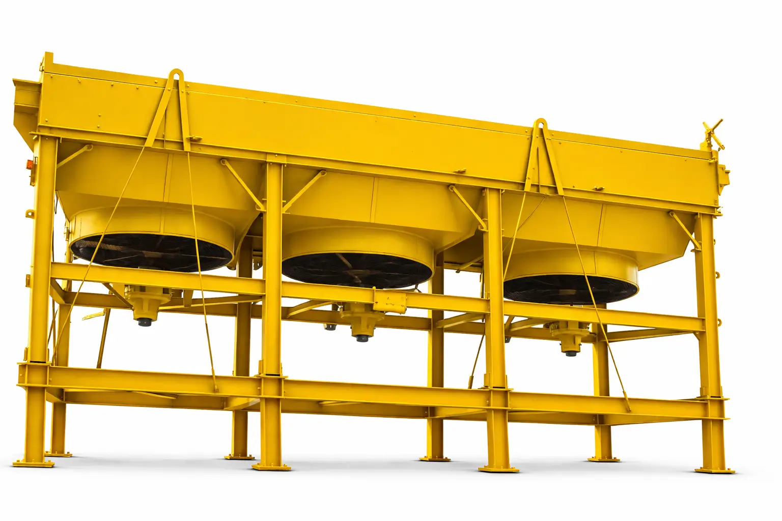
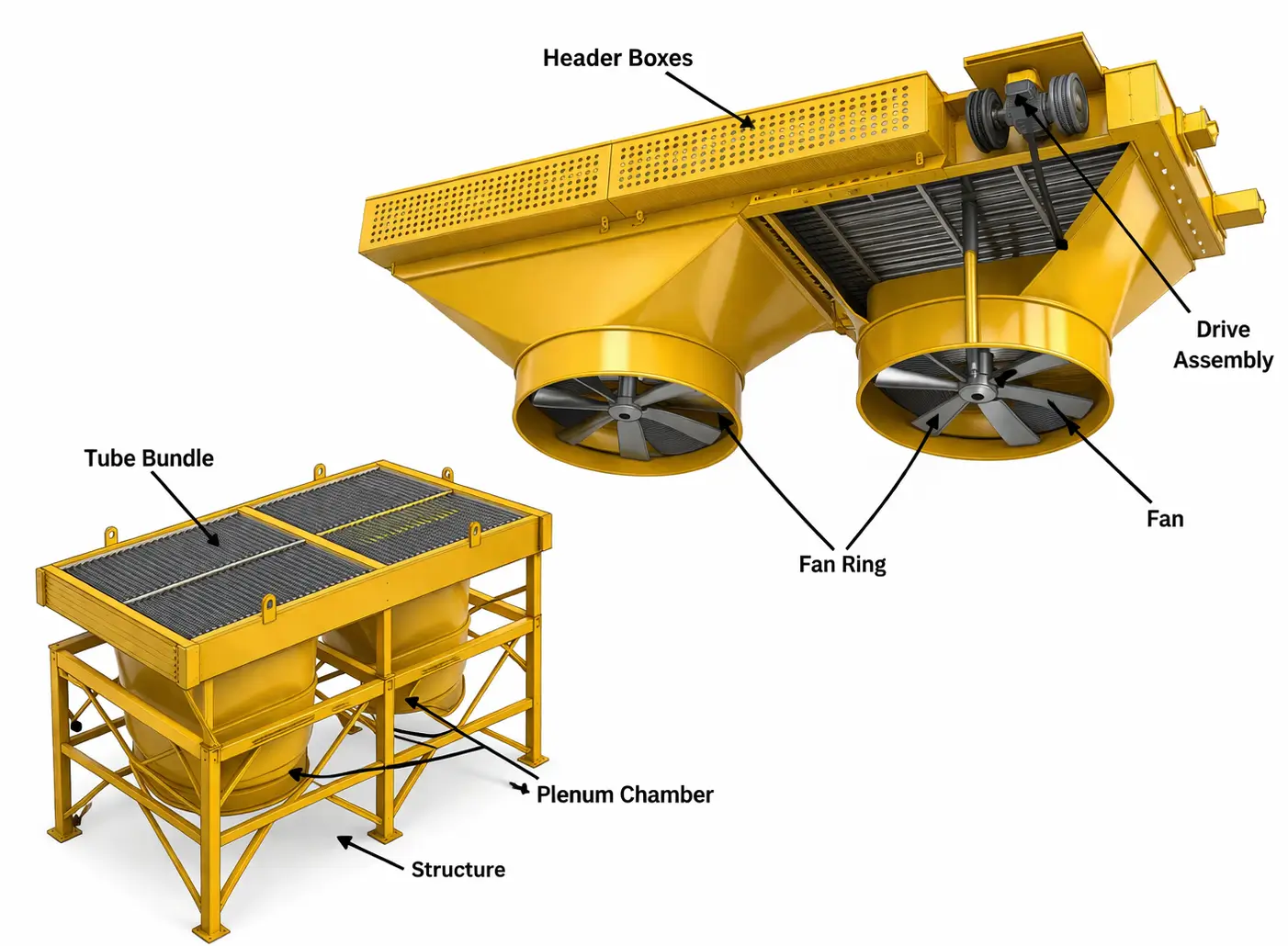
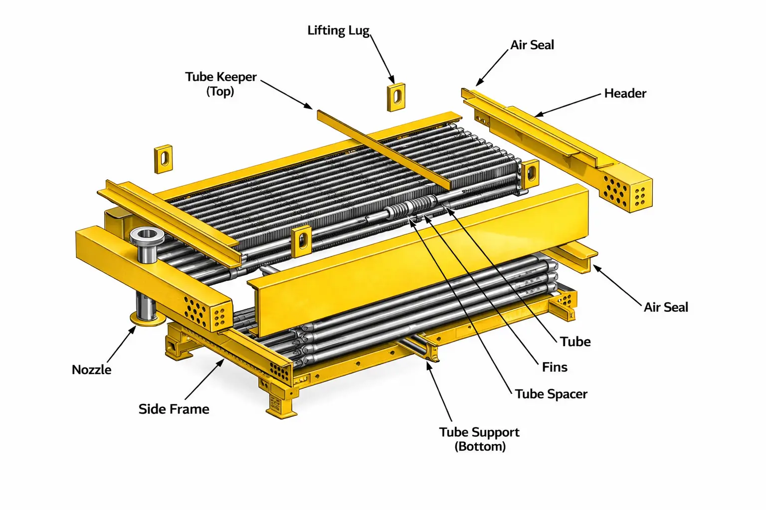
Component Description Function Key Design Rule Finned Tube Bundle Array of finned tubes — bare tubes with external fins attached or extruded — arranged in 3 to 6 tube rows across the bay width Primary heat transfer surface — process fluid flows inside the tubes; air flows across the fins on the outside More tube rows = higher heat transfer but higher air-side pressure drop and fan power. Typical: 4–6 rows for gas cooling; 3–4 rows for liquid cooling Header Boxes Rectangular pressure-containing boxes at each end of the tube bundle — one at each end per API 661 standard header types Distribute process fluid from inlet nozzle into the first tube row and collect it from the last tube row to the outlet nozzle; accommodate multi-pass flow arrangements API 661 defines four standard header box types: plug type (Type I), cover plate (Type II), manifold (Type III), and box header. Plug type is most common for refinery service — individual plug access to each tube end Plenum Chamber / Fan Stack Sheet metal enclosure below (forced draft) or above (induced draft) the tube bundle that directs fan airflow uniformly across the full bundle face area Converts high-velocity fan jet into a uniform low-velocity air stream distributed evenly over all tube rows — critical to thermal performance uniformity Plenum geometry (depth, shape) controls velocity distribution uniformity; API 661 specifies minimum fan-to-bundle clearance to prevent air short-circuiting Axial Flow Fans Large-diameter low-speed axial propeller fans — typically 40–60% of the bay area covered by fan disk; aluminum or FRP (fiber reinforced polymer) adjustable-pitch blades Generate the airflow (face velocity of 300–700 ft/min) required to achieve rated heat transfer from the tube bundle Fan pitch angle is adjusted at installation to balance airflow, static pressure, and motor amperage — critical commissioning step; variable pitch hubs allow field adjustment without stopping the fan Fan Drive System Electric motor + power transmission (direct coupling, V-belt + sheaves, or right-angle gearbox) to drive the fan at rated speed Transmit motor power to the fan; gearbox or belt arrangement reduces fan speed from motor speed to the low fan RPM required for large-diameter axial fans V-belt drives: low cost, easy belt replacement but subject to slip and require periodic re-tensioning. Gearbox drives: higher first cost but essentially maintenance-free, preferred for critical service. Direct drive with variable frequency drive (VFD): best energy efficiency for variable-load services Supporting Structure Hot-dip galvanized carbon steel frame — bents, stringers, cross-bracing, and walkways — supporting tube bundles, plenum chambers, fan stacks, and access platforms Support all static and dynamic loads — dead weight of bundles and fans, wind load, seismic load (if applicable), fan vibration, and maintenance live load on walkways Structural design per AISC LRFD or ASD; wind load per ASCE 7 or local code; seismic zone loads for applicable regions; hot-dip galvanizing for 35+ year corrosion protection in most environments Louvers Adjustable blade assemblies installed at the air inlet (forced draft) or outlet (induced draft) to modulate airflow across the bundle Control the proportion of the bundle exposed to cooling airflow — primarily used for winter operation to prevent over-cooling or freezing of process fluid or condensate Manually or automatically actuated; automatic louvers driven by pneumatic or electric actuators integrate with the temperature control system; API 661 specifies louver material and structural requirements Vibration Switch Accelerometer-based vibration sensor mounted on the fan bearing housing or structure Trips the fan motor on high vibration — protects against fan blade failure, bearing failure, or blade-to-ring contact damage that could cause catastrophic fan disintegration API 661 requires vibration switches on all fans; trip setpoint established by the fan manufacturer based on normal operating vibration level plus safety margin; requires periodic function testing
Section 2Working Principle — How Heat Is Removed by Air
Process Fluid Enters Header
Tube-Side Convection
Conduction Through Tube Wall
Fin Surface Extends Air-Side Area
Air-Side Convection
Cooled Fluid Exits
Section 3Fin Tube Types — Selection Guide
■ Embedded (KLM) Fins
■ Extruded Fins (Bimetallic)
■ L-Foot (Tension-Wound) Fins
■ Knurled (LL-Foot) Fins
■ Welded (SS or CS) Fins
■ Serrated / Spine Fins
Fin Type Max Temp Fin Material Best Service Relative Cost Embedded (KLM) 250°F (121°C) Aluminum Low-temp gas and liquid coolers, condensers below 250°F $ Extruded (Bimetallic) 300°F (149°C) Aluminum sleeve Moderate temp, clean service, maximum efficiency $$ L-Foot (Tension) 300°F (149°C) Aluminum Moderate temperature, cost-sensitive clean service $ Knurled LL-Foot 400°F (204°C) Aluminum Refinery overhead condensers, 300–400°F process coolers $$ Welded (SS/CS) 600°F+ (315°C+) Stainless or carbon steel High-temp reactor effluent, offshore marine atmosphere $$$$ Serrated / Spine 300°F (149°C) Aluminum (usually) Space-constrained clean services needing compact design $$
Section 4Header Box Types — API 661 Standard Configurations
Header Type API 661 Designation Description Access Method Best For Plug Type Type I Solid welded header with individual threaded plugs opposite each tube end — the plug is removed to access each tube individually without opening the header pressure boundary Individual plug removal per tube — no pressure boundary opening required; can access any tube without shutting down adjacent tubes Refinery and petrochemical service; high-fouling tube-side fluids requiring frequent individual tube inspection, rodding, or plugging; high-pressure service where opening the full header is undesirable Cover Plate Type Type II Removable flat cover plate bolted to the header box face — removing the single cover plate exposes all tube ends simultaneously Full header opening — all tube ends exposed at once by unbolting the cover plate; fastest access for mechanical tube cleaning General process service with moderate fouling; services requiring periodic full tube bundle hydro-blast or brush cleaning where simultaneous access to all tube ends is preferred; lower-pressure services where full header opening is practical Manifold Type Type III Cylindrical pipe manifold connected to tube ends via individual tube stubs — no rectangular header box; each tube connects individually to the manifold No tube-end access without cutting — used for fully welded, non-cleanable tube arrangements Clean services (natural gas, clean condensate, utilities) where tube-side mechanical cleaning is never required; highest-pressure services where rectangular header box wall thickness becomes prohibitive Box Header Type IV Rectangular box header — same as cover plate type but with a thicker, more heavily reinforced box structure; may have removable cover or welded construction depending on service Cover plate removal (if removable cover specified) or cut-and-weld access (if fully welded) High-pressure high-temperature service; applications requiring both mechanical strength and tube access — common on high-pressure gas compression aftercoolers and reactor effluent coolers
Section 5Fan and Drive System Design
Fan Sizing Fundamentals
Parameter Typical Range Design Significance Fan Coverage Ratio 40–60% of bay face area API 661 minimum 40%; higher coverage improves air distribution uniformity across the bundle but reduces structural clearance for maintenance Air Face Velocity 300–700 ft/min (1.5–3.5 m/s) Higher face velocity improves heat transfer coefficient but increases pressure drop and fan power; optimized during HTRI thermal design for each specific duty Fan Tip Speed Max 12,000 ft/min (61 m/s) per API 661 Higher tip speed increases noise and structural loading on fan blades and hub; API 661 limits maximum tip speed to control these effects Fan RPM 50–400 RPM depending on diameter Large-diameter fans run at low RPM — a 16 ft fan at 100 RPM moves large air volumes quietly; small fans run faster; RPM is set by the drive ratio between motor speed and fan Static Pressure 0.10 – 0.50 in W.G. typical Resistance to airflow through the fin bundle — determined by fin density, number of tube rows, and fin geometry; fan must develop sufficient static pressure at the design airflow rate Motor Power 5 hp to 200+ hp per fan Determined by airflow rate × static pressure ÷ fan efficiency × drive efficiency; oversizing by 10–15% provides a safety margin for fin fouling and higher ambient temperatures Fan Blade Materials
Drive System Selection
Drive Type Configuration Advantages Disadvantages Best Application V-Belt Drive Motor + V-belt sheaves + fan shaft Low first cost; easy belt replacement; allows fan speed adjustment by changing sheave sizes Belt slip reduces efficiency; belts require monthly tension checks; not suitable above ~50 hp per fan Small-to-medium fans up to ~50 hp where capital cost is the priority and maintenance access is straightforward Right-Angle Gearbox Motor + gearbox + fan shaft High efficiency, virtually maintenance-free; handles high power; suitable for any fan size; long service life (20+ years) Higher first cost; gearbox oil change required every 2–4 years; heavier assembly requiring heavier structure All API 661 petroleum and petrochemical service; fans above 50 hp; critical service where maintenance downtime is costly Direct Drive (VFD) Motor with adjustable-pitch blade hub, driven by VFD Maximum energy efficiency — fan speed follows process load; lowest lifecycle power cost; no belts or gearbox to maintain Highest first cost; VFD panel requires power conditioning; motor must be VFD-rated Large multi-fan units in power generation (ACCs); high-duty-cycle services with variable seasonal load; ZLD facilities targeting lowest energy consumption
Section 6Thermal Design Methodology — HTRI Approach
Key Design Inputs Required from the Client
Design Output — What HTRI Produces
Bundle Geometry
Air Face Velocity
Fan and Motor Sizing
Performance Guarantee Curve
Section 7API 661 Requirements — Class 1 vs. Class 2
Requirement API 661 Class 1 (Special Service) API 661 Class 2 (General Service) Definition Lethal, toxic, flammable at design conditions, or handling fluids that could auto-ignite — any service where a leak could result in fire, explosion, or toxic exposure All non-Class-1 services — general hydrocarbons, utilities, non-toxic process fluids Header Box Plug type (Type I) preferred — maximum containment and tube access with minimal pressure boundary opening Cover plate (Type II) acceptable for most services Tube-to-Tubesheet Joint Strength-welded (full penetration) + roll expanded — zero reliance on mechanical expansion alone Roll expanded acceptable for non-lethal, lower-pressure service NDE Requirements All pressure welds radiographically (RT) or ultrasonically (UT) examined; enhanced examination of header box welds Spot radiography of pressure welds; visual examination of fillet welds Hydrostatic Test 1.5× design pressure — witnessed by the client inspector and/or third-party inspection agency 1.5× design pressure — standard shop test Fan and Drive Right-angle gearbox drive preferred; vibration switch mandatory; backup fan capability required for critical services V-belt drive acceptable for smaller fans; vibration switch required per API 661 Vibration Analysis Mandatory — API 661 requires analysis of flow-induced vibration for all tube rows; fan vibration analysis to verify no resonance with structural natural frequency Required for long unsupported tube spans; vibration analysis per TEMA/API guidelines Documentation Package Full vendor data package: design calculations, material certifications (MTRs), weld maps, NDE reports, ASME U-1 MDR, API 661 data sheets, fan performance test data Standard documentation: data sheet, MTRs, ASME documents, hydrostatic test certificate
Section 8Noise Control and Acoustic Design
Primary Noise Sources
Noise Mitigation Measures — in Order of Effectiveness
Mitigation Measure Noise Reduction Cost Impact Notes Reduce fan tip speed High — dominant effect Requires larger fan diameter or fewer bays — moderate cost increase Most effective primary noise control measure; reducing tip speed from 12,000 to 8,000 ft/min reduces fan noise by ~8–10 dBA Increase number of fan blades Moderate Low — blade count change only More blades at lower pitch achieves same airflow at lower tip speed; 8–12 blade fans quieter than 4–6 blade fans for same diameter Variable frequency drive (VFD) High at part-load Significant — VFD panel required Fan noise scales approximately with fan speed cubed — reducing fan speed by 20% at night or in cooler seasons reduces noise by ~7 dBA Acoustic enclosures / baffles 10–20 dBA at fence line High — significant structural and civil work Last resort for retrofits where other measures are insufficient; enclosures must not restrict airflow to the fan inlet Low-noise fan blades 3–6 dBA Low–moderate Airfoil-section blades with serrated trailing edges reduce vortex noise; specify as a design requirement in the fan datasheet
Section 9Winterization — Protecting Air Fin Coolers in Cold Climates
Winterization Design Features
Adjustable Louvers
Hot Air Recirculation Duct
Steam Coils (Freeze Protection)
Variable Pitch Fans
Insulated Bundle
Trace Heating
Section 10Materials of Construction
Component Material Standard Service Key Note Tubes (Process) Carbon steel seamless ASTM A179 / A214 General process hydrocarbons, steam, clean utilities Standard for refinery and gas plant service; add corrosion allowance for H₂S, CO₂, organic acids Tubes (Process) 304 / 316L stainless steel ASTM A213 TP304/316L Mildly corrosive process, amine solutions, sour gas with low chlorides 316L preferred where chloride stress corrosion cracking is a risk above 140°F Tubes (Process) Duplex 2205 ASTM A789 S31803 High-chloride, sour service (H₂S + Cl⁻), offshore production fluids NACE MR0175 hardness compliance required in H₂S service Tubes (Process) Alloy steel (P9/P11/P22 chrome-moly) ASTM A213 Gr. T9/T11/T22 High-temperature reactor effluent coolers above 700°F Post-weld heat treatment (PWHT) required; specialist welding qualifications needed Fins (Air Side) Aluminum alloy 1100 or 3003 ASTM B221 Standard for all services in clean-to-moderate atmospheres below 300°F Not suitable above 300°F (embedded/extruded) or 400°F (knurled); not for marine coastal atmospheres without protective coating Fins (Air Side) Carbon steel (galvanized or painted) ASTM A109 High-temperature service above 400°F; cost-sensitive inland sites Hot-dip galvanize or epoxy coat for outdoor corrosion protection; same material as tube for welded fins Fins (Air Side) 304 / 316L stainless steel ASTM A167 Marine, offshore, chemical plant atmospheres where aluminum fins corrode Required within ~1 mile of saltwater; higher cost than aluminum but 35+ year life in marine environments Header Boxes Carbon steel plate ASTM A516 Gr. 70 General process hydrocarbons, utilities Add corrosion allowance per API 661 minimum; weld overlay or cladding for corrosive tube-side fluids Header Boxes 304L / 316L stainless ASTM A240 Corrosive process fluids, amine service, pharmaceutical, food-grade Full SS header avoids cladding bonding concerns; higher cost but more reliable for highly corrosive services Supporting Structure Carbon steel — hot-dip galvanized ASTM A36 / AISC Standard for inland, non-marine environments Hot-dip galvanizing provides 25–30 year corrosion protection in most industrial environments; repainting required at 15–20 years Supporting Structure Carbon steel — epoxy + polyurethane topcoat SSPC painting standards Marine, offshore, chemical plant atmospheres Multi-coat high-build epoxy system; 10–15 year repainting interval; critical for structures within 1 mile of saltwater Fan Blades Aluminum alloy — Standard for most forced and induced draft service below 300°F exit air temperature HVOF or anodize treatment for marine atmosphere fan blades Fan Blades FRP (fiberglass reinforced polymer) — Marine and coastal offshore atmosphere; chemical plant atmospheres; large-diameter fans UV-stabilized resin system required for outdoor service; superior atmospheric corrosion resistance
Section 11Air Fin Cooler vs. Water-Cooled Heat Exchanger — Engineering Comparison
Attribute Air Fin Cooler Water-Cooled Shell & Tube Cooling Medium Ambient air — free and unlimited supply Cooling water — requires cooling tower, pumps, and treatment system Water Consumption Zero High — 4,000–6,000 GPM per 100 MW heat duty (evaporation + blowdown) Minimum Process Outlet Temperature Limited by ambient dry-bulb temperature — typically outlet must be 15–25°F above ambient Can achieve lower outlet temperatures — limited by cooling water inlet temperature (typically 75–95°F) Capital Cost Higher first cost for the ACHE itself — large structure, fans, motors Lower exchanger cost — but must include cooling tower, pumps, water treatment system in total installed cost Total System Operating Cost 30–50% lower over plant life — no water, no chemicals, no blowdown disposal Higher — cooling water procurement, treatment, blowdown disposal, and pump energy Fouling No water-side fouling — fin side exposed to atmospheric dust only Cooling water fouling on tube side requires periodic cleaning; scale, biological, and MIC fouling common Site Applicability Suitable for arid, remote, offshore, and ZLD sites with no water access Requires adequate cooling water supply — impractical in water-scarce regions without major infrastructure Plot Area Large — ACHE structure can be 50–200% larger in plot footprint than equivalent S&T + cooling tower system Smaller total footprint (exchanger + cooling tower) for equivalent heat duty Legionella Risk Zero — no water in the cooling system Present — cooling tower water systems are a known Legionella risk requiring rigorous biocide management Performance in Hot Weather Performance degrades on hot days — ambient temperature directly limits outlet temperature More stable performance — cooling water temperature varies less than air temperature seasonally Environmental Permit No water discharge permit required — zero liquid effluent Cooling tower blowdown discharge requires permit in most jurisdictions
Section 12Performance Troubleshooting Guide
Symptom Most Likely Cause Diagnostic Check Corrective Action Process outlet temperature above design at rated ambient temperature Fin fouling reducing air-side heat transfer; reduced airflow from incorrect fan blade pitch angle or belt slip; hot air recirculation; blocked air inlet Measure fan amperage and compare to design; visually inspect fin surface for dust and debris; check blade pitch angle; check for recirculation by observing air flow pattern with smoke Clean fin surface (high-pressure water or steam); readjust fan blade pitch angle; add or extend recirculation baffles; clear air inlet obstructions Process outlet temperature below design in winter Ambient temperature below design basis — over-cooling; louvers not closing adequately; recirculation system not activated Check ambient temperature vs. design minimum; verify louver actuator operation; check recirculation duct damper position Close louvers to reduce airflow; activate hot air recirculation; reduce fan blade pitch angle; consider VFD fan speed reduction if available High tube-side pressure drop Tube-side fouling or partial blockage; incorrect pass arrangement; plugged nozzle or strainer Compare current ΔP against design at same flow rate; check inlet strainer; inspect header boxes for debris Clean tube side (via header box or plug access); remove and clean inlet strainer; verify pass partition integrity in header boxes Fan vibration alarm or trip Blade damage or blade-to-ring contact; bearing failure; blade pitch inequality between blades; foreign object ingestion; structural resonance Stop fan immediately; inspect blades visually for damage, pitch angle equality, and tip clearance to fan ring; check bearing condition (temperature, noise) Replace damaged blades; re-pitch all blades to equal angle; replace failed bearings; clear fan ring obstructions; check for structural resonance at operating speed Hot spots on tube bundle surface (visible corrosion or discoloration) Fin loss or fin detachment from tube surface — loss of extended surface dramatically reduces local heat transfer; process fluid temperature rises at the de-finned zone Visual inspection of fin surface from ground and with binoculars from access walkways; eddy current inspection of tubes in the affected zone Replace fin-damaged tube sections if feasible in removable bundle designs; accelerate bundle replacement schedule if fin loss is widespread; investigate cause (vibration fatigue, corrosion, mechanical damage) Tube-side leakage (process fluid dripping from header boxes) Plug thread failure in plug-type headers; tube-to-tubesheet joint failure; header box weld cracking from thermal fatigue or pressure cycling Identify leak source (plug vs. tube vs. weld); hydrostatic test to locate failed joints; radiographic inspection of suspect welds Replace failed plugs immediately; plug failed tube ends from both header sides; repair or replace cracked welds using qualified ASME weld procedures; investigate root cause (pressure cycling, vibration, corrosion)
Section 13Maintenance and Inspection Manual
Daily / Weekly Monitoring KPIs
Monthly Maintenance
Annual Inspection
Major Inspection (Every 5 Years or at Turnaround)
Section 14Standards and Codes Reference
Standard / Code Issuing Body Scope Application to Air Fin Coolers API Standard 661 API Air-cooled heat exchangers for petroleum, petrochemical, and natural gas service — complete design, fabrication, testing, inspection, and documentation requirements Primary governing standard for all air fin coolers in refinery, petrochemical, and gas processing service — specifies header box types, tube-to-tube sheet joint requirements, fan tip speed limits, vibration switch requirements, and vendor data package ASME BPVC Section VIII Div. 1 & 2 ASME Pressure vessel design, fabrication, inspection, testing, U-Stamp certification All tube bundle pressure components — header boxes, tubes, tube sheets, and nozzles; mandatory U-Stamp for all petroleum and petrochemical air fin coolers ASME BPVC Section IX ASME Welding procedure and welder performance qualification All pressure welds in header boxes, tube-to-tube sheet joints, and nozzle-to-header welds ASME B31.3 Process Piping ASME Process piping design Inlet and outlet process piping nozzles connected to the header box; operating pressure relief provisions AISC Steel Construction Manual AISC Structural steel design — LRFD or ASD methods Supporting structure design: columns, beams, bracing, walkway platforms, and stairways; wind load and seismic load combinations per ASCE 7 ASCE 7 ASCE Minimum design loads for buildings and other structures — wind, seismic, dead, and live loads Wind load on tube bundles, plenum chambers, and structural frame; seismic loads for applicable seismic zones; required input to structural design of the ACHE support structure AMCA Standard 210 AMCA Laboratory methods of testing fans for certified aerodynamic performance ratings Fan airflow, static pressure, and power draw certification; required when client specifies factory-witnessed fan performance testing in the vendor data requirement NEMA MG-1 NEMA Motors and generators — design, fabrication, and testing standards All electric motors for fan drives; NEMA Premium efficiency rating standard; TEFC or TENV enclosure requirements; hazardous area (ATEX/NEC 500/505) rating for Class I Div. 1 or 2 locations IEC 60079 (ATEX) IEC / ATEX Electrical equipment for explosive atmospheres Fan drive motors in hazardous electrical classification areas (common in refinery and offshore ACHE installations) NACE MR0175 / ISO 15156 NACE / ISO Material qualification for H₂S sour service Tube bundle material qualification when the process fluid contains H₂S — required for all oil and gas production and refinery ACHE applications with sour service designation ISO 9001:2015 ISO Quality management system Governs all engineering, procurement, fabrication, inspection, testing, and documentation processes at United Heat Exchangers Request a Quote from United Heat Exchangers — Air Fin Cooler Manufacturer in India
← Back to Air Fin Cooler Product PageSection 1
Tube Bundle Finned tubes + headers
Header Box Plug / cover plate type
Fan Stack Plenum + fan ring
Axial Fans Aluminum or FRP blades
Drive System Motor + gearbox / belt
Supporting Structure Steel frame + walkways
Louvers Airflow control
Vibration Switch Fan trip protection
01
02
03
04
05
06
T1
T2
T3
T4
W1
W2
W3
W4
W5
W6