Author: Senthil Kumar, Technical Director | Updated: June 2026
Table of Contents
What Is an Air Cooled Heat Exchanger?
An air cooled heat exchanger (ACHE), also called a fin fan cooler, cools process fluid inside finned tubes using motor-driven fans and ambient air. No cooling water. No cooling tower. No water treatment. The atmosphere itself is the coolant.Aluminium fins extend the external tube surface 15–25× over bare tube, compensating for air's low heat transfer coefficient. United Heat Exchangers designs and manufactures ACHEs to API 661 and ASME Section VIII for refineries, gas plants, petrochemical plants, and power generation clients across India and 30+ export markets.
How an Air Cooled Heat Exchanger Works
Hot fluid enters the inlet header, flows through finned tubes in one or more passes, and exits cooled at the required outlet temperature. Axial fans simultaneously drive ambient air across the fin surface — heat transfers through the tube wall and fins into the airstream, which exits warm to atmosphere.
Fluid Enters Header
Hot process fluid enters the inlet header and distributes across all tube passes.
Flows Through Finned Tubes
Fluid transfers heat through tube walls and aluminium fins into the passing airstream.
Fans Drive Airflow
Axial fans move high air volumes across the bundle at low static pressure drop.
Cooled Fluid Exits
Process fluid leaves the outlet nozzle at the required design outlet temperature.
Warm Air Discharged
Air exits 5–15°C above ambient. No water consumed, no effluent produced.
Engineering Insight — Sizing and Approach Temperature: The governing equation is Q = U × A × CMTD, where CMTD = F × LMTD. F corrects for cross-flow: with one tube pass F falls well below 1.0; four or more passes approaches true counter-current behaviour (F → 1.0). Critically, an ACHE cannot cool process fluid below the ambient dry-bulb temperature — the practical minimum approach is 10–15°C.
Types of Air Cooled Heat Exchangers
These four configurations cover the full range of refinery, gas, and process duties. United Heat Exchangers manufactures all types to API 661 with ASME U-Stamp certification.
Forced Draft Air Cooled Heat Exchanger
Fan below bundle — pushes air upward through finsFans below the bundle push ambient air upward through finned tubes. The drive train sits at grade level — fully accessible for maintenance without scaffolding.
- Fan and motor at grade — easy inspection and V-belt or gearbox service
- Lower inlet air temperature to fan — better bearing life and efficiency
- Standard for hydrocarbon coolers and compressor inter- and after-coolers
- API 661 forced-draft geometry with plenum chamber below the bundle
Induced Draft Air Cooled Heat Exchanger
Fan above bundle — draws air upward through finsFans above the bundle pull air up through the fins, giving more uniform airflow and better resistance to hot-exhaust recirculation — preferred for hot climates and offshore.
- Fan draws evenly across the full bundle face — most uniform air distribution
- Bundle shielded from rain, hail, and direct sun by the fan deck above
- Hot exhaust discharges at high upward velocity — lower recirculation risk
- Standard for LNG, gas processing, offshore, and close-approach duties
Plug Header — API 661 Type B
 Individual tube access without header removal
The header face is drilled and threaded with a plug opposite each tube end. Unscrewing any plug gives direct cleaning or inspection access to that tube — the rest stays in service.
- Tube-by-tube access without removing the header box
- Defective tubes individually plugged without shutdown
- API 661 default for most refinery and gas plant services
- Available in carbon steel, 316L SS, duplex, and high alloy
Cover Plate Header — API 661 Type A
 Full face access for severe fouling services
A bolted, gasketed cover plate exposes all tube ends simultaneously — the fastest, most complete cleaning access for heavily fouling process streams.
- All tube ends exposed at once for simultaneous mechanical cleaning
- Preferred for crude overhead, residue, heavy fuel oil, and slurry services
- Gasketed joint must be correctly re-sealed after each cover removal
- Available in carbon steel, stainless steel, and alloy construction
Key Components of an Air Cooled Heat Exchanger
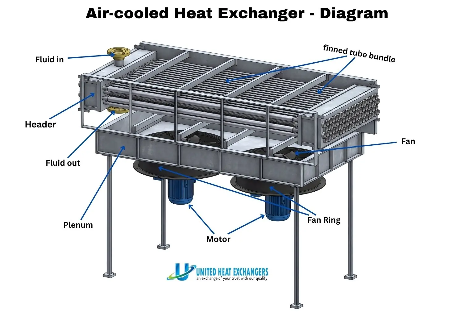
Finned Tube Bundle
The heat transfer core. Aluminium fins wound, embedded, or extruded onto carbon steel, stainless, or alloy tubes extend the external surface 15–25×. Tubes are arranged on triangular pitch in 3–6 rows in the direction of airflow.
Tube Headers
Box headers at each end distribute fluid to the tubes and define the pass arrangement. API 661 specifies four header types (A/B/C/D). Each header is a standalone ASME Section VIII pressure vessel — designed, hydro-tested, and U-Stamped independently.
Flow Fans
Propeller-type fans with 4–6 aerofoil blades move large air volumes at low static pressure. Fixed pitch for simple duties; auto-adjustable pitch for precise outlet temperature control and off-season fan power savings.
Fan Drive — Motor, Gearbox or V-Belt
An electric motor drives the fan via V-belt (up to ~55 kW) or right-angle gearbox (larger fans). Variable frequency drives (VFDs) add continuous speed control — fan power drops with the cube of speed reduction.
Plenum Chamber
The enclosure between fan ring and bundle smooths and distributes airflow across the full bundle face. Slope-sided plenums give the most uniform distribution; box plenums are standard for forced-draft units.
Structural Frame
Columns, cross-beams, and bracing elevate the unit for adequate air inlet and carry all dead, live, wind, and seismic loads to the foundation. In refineries, the frame is commonly mounted above a pipe rack to maximise plot utilisation.
Engineering Advantages of Air Cooled Heat Exchangers
Zero Cooling Water Required
No cooling tower, circulating pumps, water treatment, blowdown, or Legionella risk. The default choice for water-scarce regions — India, the Middle East, and sub-Saharan Africa.
Lower Total Life-Cycle Cost
Higher equipment unit cost than shell-and-tube, but eliminating cooling water infrastructure — tower, pumps, chemical dosing, make-up water — delivers lower total installed and operating cost for most large process duties.
No Cooling-Water Corrosion
The tube exterior contacts only clean air. Corrosion management focuses entirely on the process side, eliminating shell-side biofouling, scaling, and chloride pitting that plague water-cooled exchangers.
Simple, Robust Construction
No internal baffles, floating heads, or shell-side gaskets. Finned tubes between two headers — mechanically straightforward, easy to inspect, and resilient to process upsets and pressure transients.
Modular Capacity Expansion
Add fan bays, install VFDs, switch to auto-variable pitch fans, or add evaporative assist — without replacing tube bundles or the structural frame. The lowest-cost route to capacity growth on an existing unit.
Zero Liquid Effluent
No blowdown, no chemical discharge, no thermal pollution to waterways. ACHEs eliminate the water-discharge permitting complexity and ongoing regulatory risk associated with wet cooling systems.
Design Standards — API 661 and ASME
Every air cooled heat exchanger from United Heat Exchangers is designed, inspected, and documented to the following codes.
| Standard | Scope | Key Output |
|---|---|---|
| API Standard 661 (8th Edition) | Complete ACHE mechanical specification — header type, fin tube geometry, fan design rules, structural frame loads, inspection, testing, and documentation | Signed API 661 data sheet; unit nameplate; complete documentation package |
| ASME Section VIII Div. 1 | All pressure-containing components — headers, nozzles, bonnets — wall thickness, weld NDE, and hydrostatic test at 1.3× MAWP | ASME U-Stamp; Manufacturer's Data Report (Form U-1) signed by Authorised Inspector |
| HTRI Xace Software | Rigorous thermal rating — air-side and tube-side heat transfer, pressure drop, fin efficiency, and fan performance at design and off-design ambient temperatures | Guaranteed thermal performance certificate; seasonal performance curves |
| NACE MR0175 / IBR | NACE: material hardness limits and PWHT for H₂S sour service. IBR: mandatory for steam-service ACHEs in India — drawing approval, witnessed hydrostatic test, and IBR certificate before dispatch | NACE compliance statement; IBR certificate issued before despatch |
Specification Tip: An API 661 data sheet locks in all process, thermal, and mechanical requirements before manufacture begins. Share your process datasheet and United Heat Exchangers will complete and return a draft API 661 data sheet within 48 hours as part of the technical proposal.
Industries and Applications
| Industry | Typical Duty | Process Stream | Header / Fan Type |
|---|---|---|---|
| Petroleum Refining | Atmospheric and vacuum overhead condensers; product coolers; reformate cooler | Crude overhead vapour; naphtha; kerosene; gas oil; H₂-rich reformer gas | Plug header (Type B); forced or induced draft per process inlet temperature |
| Gas Compression | Reciprocating and centrifugal compressor inter-coolers and after-coolers | Compressed natural gas, process gas, instrument air, nitrogen | Plug header; auto-variable pitch fans for precise outlet temperature control |
| Natural Gas Processing | Lean and rich amine coolers; glycol cooler; residue gas cooler; NGL cooler | Amine (H₂S/CO₂ absorption); TEG/MEG dehydration; NGL condensate streams | Plug or cover plate header; 316L SS tubes for amine and glycol service |
| Power Generation | Steam turbine exhaust air cooled condenser (ACC); lube oil and transformer oil coolers | LP steam at sub-atmospheric pressure; turbine lube and seal oil | Large multi-bay induced draft; VSD fans; condensate collection headers |
| Offshore & Marine | Platform wellhead gas cooler; produced water cooler; gas export compressor after-cooler | Wellhead gas; high-chloride produced water; high-pressure export gas on FPSOs | Induced draft; duplex or super duplex tubes; epoxy-coated aluminium fins |
Air Cooled vs Water Cooled Heat Exchanger
| Parameter | Air Cooled Heat Exchanger | Water Cooled Shell-and-Tube |
|---|---|---|
| Cooling Medium | Ambient air — free and unlimited; requires fan power only | Cooling water — tower, pumps, and treatment infrastructure required |
| Min. Outlet Temperature | Typically 10–15°C above ambient dry-bulb temperature | Typically 5–10°C above cooling water supply temperature |
| Water Consumption | Zero | Significant — tower evaporation, blowdown, and make-up water daily |
| Total Installed Cost | Higher unit cost but no water infrastructure — lower total for large duties | Lower unit cost but high total infrastructure cost including tower and pumps |
| Corrosion Risk | No cooling-water corrosion on tube exterior — air only contacts the fins | Shell-side biofouling, scaling, and chloride pitting from cooling water |
| Environmental Impact | No liquid effluent; no thermal discharge to waterways; no chemical blowdown | Blowdown chemicals; thermal discharge; Legionella risk management required |
When to Choose Air Cooling: Air cooling is the right choice wherever cooling water is scarce, restricted, or expensive, and wherever environmental discharge permits are difficult to obtain. If the required process outlet temperature falls below the ambient dry-bulb limit, a small downstream water-cooled trim cooler handles the remaining duty.
Why United Heat Exchangers
API 661 Specialist Manufacturer
Every ACHE we build is designed to API 661 — all header types (A/B/C/D), forced and induced draft, all tube materials from carbon steel to super duplex and Hastelloy, with a complete documentation package on every order.
HTRI Xace Thermal Guarantee
Bundle geometry, fin type, pass arrangement, and fan sizing are optimized in HTRI Xace. We issue a guaranteed thermal performance certificate at design ambient and off-design performance curves across the full seasonal range.
ASME U-Stamp + IBR Certified
Header pressure parts carry the ASME U-Stamp with full Manufacturer's Data Reports. Steam-service units are IBR-approved — drawings, calculations, and hydrostatic test certification all handled in-house before dispatch.
30+ Countries — Full In-House Engineering
From process datasheet to certified fabrication drawing — thermal design, fan selection, structural design, and export documentation — entirely in-house, no subcontracting. Delivered to 30+ countries with ASME, NACE, and ATEX compliance.
Get a Free Air Cooled Heat Exchanger Quote in 48 Hours
Send your process duty, fluid properties, design ambient temperature, and site location. We return an HTRI-sized thermal proposal, fan and motor selection, and a completed API 661 data sheet within 48 hours.
Request My Free Quote →Delivery and What's Included
- HTRI Xace thermal performance guarantee — air-side and tube-side heat transfer and pressure drop at design ambient, with overdesign margin clearly documented
- Signed API 661 data sheet — fin tube specification, fan data, header type, nozzle schedule, and nameplate data for the as-designed unit
- ASME U-Stamp and Manufacturer's Data Report (Form U-1) — for all header pressure parts, signed by Authorised Inspector; MAWP and design temperature stamped on nameplate
- IBR documentation — for steam-service units: IBR drawings, calculations, and hydrostatic test certificate before dispatch
- Material certifications and NDE reports — traceable mill test reports for all pressure parts; RT/UT for pressure butt welds; MT/PT for fillet welds, signed by ASNT Level II inspector
- Operations and maintenance manual — fin cleaning procedure, tube-side cleaning (plug header), fan pitch resetting, gearbox service intervals, and 2-year spare parts list
Frequently Asked Questions — Air Cooled Heat Exchanger
What is an air cooled heat exchanger?
An air cooled heat exchanger (air fin cooler or fin fan cooler) cools process fluid inside finned tubes using motor-driven axial fans and ambient air — eliminating cooling water entirely. All units are designed to API 661 with pressure-containing components built to ASME Section VIII Division 1.
What is the difference between forced draft and induced draft?
Forced draft places fans below the bundle and pushes air upward — drive is at grade level for easy maintenance. Induced draft places fans above and pulls air upward — giving more uniform airflow, lower hot-exhaust recirculation risk, and better bundle protection from weather. Induced draft is preferred for hot climates and offshore; forced draft where drive maintenance access is the priority.
What is the minimum outlet temperature an air fin cooler can achieve?
An ACHE cannot cool process fluid below ambient dry-bulb temperature. In practice, the minimum process outlet is 10–15°C above ambient. For lower outlet temperatures, a small downstream water-cooled trim cooler handles the remaining cooling duty.
What is the difference between API 661 and ASME Section VIII?
API 661 is the complete equipment specification — it governs header type, fin tube design, fan sizing, structural loading, and the full inspection and testing programme. ASME Section VIII governs only the pressure-containing components (headers and nozzles). Both apply together: ASME ensures pressure safety; API 661 ensures the full unit is correctly designed for process service.
How do you clean an air cooled heat exchanger?
Fins are cleaned air-side with high-pressure water at 45–60° to avoid fin damage. Plug header units (API 661 Type B) allow tube-side mechanical or hydro-jet cleaning tube-by-tube without removing the header. Cover plate header units give simultaneous access to all tube ends after removing the bolted cover.
What is the lead time for an air cooled heat exchanger from India?
Standard forced-draft units in carbon steel or 316L SS deliver in 6–10 weeks. Alloy bundles, induced-draft, multi-bay, ASME U-Stamp, or IBR-approved units take 12–20 weeks. Expedited delivery is available for plant shutdowns and emergency replacements — contact us with your timeline.
Author: Senthil Kumar, Technical Director — United Heat Exchangers Pvt. Ltd. | Last Updated: June 2026