Author: Senthil Kumar, Technical Director | Updated: May 2026
Table of Contents
- What Is an Intercooler?
- How It Works
- Types of Intercoolers
- Key Components Explained
- How an Intercooler Reduces Compressed Gas Temperature
- Design Specifications and Standards
- Material Selection Guide
- Industries and Applications
- How to Select an Intercooler
- Performance Benefits of Proper Intercooling
- Why United Heat Exchangers
- Delivery and What's Included
- Frequently Asked Questions
- Request a Free Quote

What Is an Intercooler?
An intercooler is a heat exchanger that cools compressed gas between stages of compression, or after final compression before the gas enters the process or application. Hot compressed gas exits one compressor stage, flows through the intercooler where ambient cooling reduces its temperature, and then enters the next compression stage cooler and denser than it otherwise would be.
The result: lower compression work for the next stage, improved overall system efficiency, extended compressor component life, and reduced energy consumption. In multi-stage turbocharged engines, intercoolers are the difference between acceptable and exceptional power density. In industrial compressors and gas processing, they are the foundation of efficiency and long-term operational reliability.
As a leading intercooler manufacturer in India, United Heat Exchangers designs and manufactures air-cooled and water-cooled intercoolers for turbocharged diesel and petrol engines, multi-stage gas compressors, power generation, marine diesel systems, and industrial pneumatic service — all engineered and tested to your exact flow, pressure, and temperature specifications.
How an Intercooler Works
The operating principle is straightforward: hot compressed gas flows through passages inside tubes or plates. Cooling medium — ambient air or water — flows outside or in adjacent channels. Heat transfers from the hot gas to the cooling medium. The gas exits cooler, at lower density, ready for the next compression stage or final use.
Hot Gas Enters Inlet
Compressed gas exiting a compressor stage enters the intercooler inlet nozzle at elevated temperature — typically 60–150°C depending on the compressor type and pressure ratio.
Distributes Into Tube/Plate Matrix
Inlet header routes the hot gas into parallel tubes or channel passages. The multiple-passage arrangement maintains manageable gas velocity and pressure drop through the cooler.
Heat Transfers Through Walls
Cooling medium — ambient air or water — removes heat from the gas through the tube or plate wall. Fins or extended surfaces amplify the cooling capacity per unit of core volume.
Gas Temperature Falls
As heat leaves, the gas temperature drops progressively along the cooling path. Outlet temperature is controlled by the intercooler size and cooling medium temperature and flow rate.
Cooled Gas Exits
Gas exits the outlet nozzle at reduced temperature — denser and containing less heat energy per unit mass than when it entered. Condensate and particulate may be collected in a drain or separator downstream.
💡 Temperature reduction is work reduction: Every degree of gas temperature reduction entering the next compressor stage reduces the work required for that stage. A properly sized intercooler cooling gas from 100°C to 50°C between stages reduces the final compression stage energy requirement by approximately 5–8% compared to an undersized or poorly designed intercooler that delivers gas at 80°C.
Types of Intercoolers
Intercoolers are classified by the cooling medium used and the internal structure. Each type offers different compromises between cost, size, cooling capacity, and pressure drop characteristics.
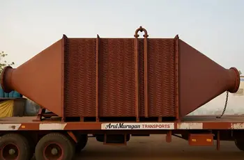
Air-Cooled Intercooler
Ambient air as cooling medium — no water requiredFinned tube or bar-plate core with ambient air flowing across the fins — driven by vehicle motion (ram air), a separate fan, or the engine cooling fan. Ambient air inlet temperature limits the outlet gas temperature achievable. Most cost-effective for engine and mobile compressor service.
- Most common intercooler type in turbocharged diesel and petrol engines
- No cooling water supply or cooling system required
- Outlet gas temperature limited by ambient air temperature — hot climates reduce cooling effectiveness
- Minimal maintenance — periodic fin cleaning for dust and dirt accumulation
- Compact design fits engine bay space constraints in automotive and marine applications
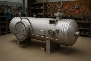
Water-Cooled Intercooler
Process coolant as cooling medium — superior performance, higher costTube-and-fin or bar-plate core with process cooling water circulating through the jacket. Water temperature can be maintained at optimum levels independent of ambient conditions — delivering superior and stable gas outlet temperature across all seasons and climates. Standard in stationary compressors and large industrial diesel engines.
- Delivers the coldest practical outlet gas temperature — best efficiency and maximum power
- Performance independent of ambient temperature — stable year-round in extreme climates
- Requires cooling water circuit — additional pump, piping, and heat rejection capacity
- Water side requires corrosion inhibitor maintenance and periodic flushing
- Specified for mission-critical applications where performance stability is mandatory
Plate-Fin Intercooler
High surface area density — compact multi-stage designCorrugated fins brazed between flat plates in a stacked configuration. Multiple gas passes and a water jacket create a very compact core with high surface area per unit volume. Most efficient cooling in the smallest footprint. Common in large industrial compressor trains and specialized process applications.
- Highest cooling capacity per unit volume among all intercooler types
- Water-cooled construction required — cannot be used with air cooling alone
- Very low gas-side pressure drop relative to cooling capacity
- Multi-pass configurations for close temperature approach and staged cooling
- Brazing construction is permanent — individual core damage requires full core replacement
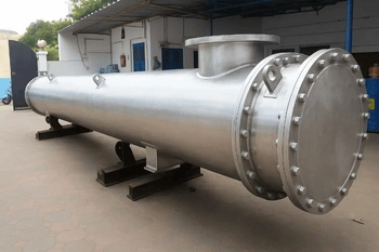
Shell-and-Tube Intercooler
Modular, long service life — standard industrial compressor designStraight tubes carrying hot compressed gas, with cooling water in the shell around them. Tube-side is the gas circuit; shell-side is the water circuit. TEMA design permits thermal expansion without stress. The most conservative pressure rating and longest expected service life in multi-stage industrial gas compression.
- Highest design pressure capability — suitable for ultra-high-pressure gas compression
- Fully disassemblable — tubes can be individually cleaned or replaced without component replacement
- Most robust construction for contaminated or corrosive gas streams
- Larger and heavier than plate-fin for equivalent cooling capacity
- Standard specification for stationary industrial gas compressor systems worldwide
Regenerative Intercooler
Integrating cooling with heat recovery — future-focused designA rotating drum of thermally massive material — wire mesh, ceramic, or metal matrix — passes alternately through the hot compressed gas stream and a water spray or cooling circuit. Heat is absorbed by the drum when passing through the gas stream, and shed to the cooling circuit when passing through the spray zone.
- Extremely compact relative to cooling capacity — nearly 50% smaller than bar-plate equivalents
- Constant outlet gas temperature independent of inlet gas temperature swings
- More complex control system required for drum rotation and spray timing
- Specified for large variable-load compressors where gas inlet temperature swings are significant
- Higher capital cost — justified by space savings and superior performance stability
Key Components Explained
Tube Bundle (Gas-Side)
The primary heat transfer surface. Tubes carry hot compressed gas from inlet header to outlet header. Tubes are finned on the outside (air-cooled) or bare inside tubes with a water jacket (water-cooled). Material selected to withstand the gas pressure rating and resist any corrosive constituents in the compressed gas stream.
Cooling Medium Circuit
In air-cooled intercoolers: fins on tubes conduct heat from gas into the external air — either from the engine cooling fan or from vehicle motion (ram air). In water-cooled intercoolers: a water jacket surrounding the gas tubes carries the cooling water and absorbs heat continuously. Water circuit is fed from the main engine or system cooling loop.
Inlet Header
Large-diameter chamber on the gas inlet side that receives hot compressed gas and distributes it evenly into all parallel tubes. Header size and design prevent velocity-induced erosion or pressure drop concentration on a few tubes — ensuring uniform gas distribution across the entire tube bundle.
Outlet Header
Collects cooled gas exiting all parallel tubes and directs it toward the outlet nozzle. Design prevents any single stream from dominating — ensuring the coldest possible composite outlet gas temperature by allowing all tube streams to mix thoroughly before exiting.
Inlet and Outlet Nozzles
Flanged or threaded connections on the gas inlet and outlet. Nozzle size matches the piping diameter to minimise erosion and pressure drop in the approach and discharge pipework. Flange material and gasket rated to the design pressure and temperature of the compressed gas.
End Tanks (Water-Cooled)
Large chambers at each end of the tube bundle — the water inlet tank at one end, water outlet tank at the other. The water path routes coolant into the inlet tank, down through the tube bundle in counter-current or cross-flow arrangement against the gas flow, and exits through the outlet tank. Separation between inlet and outlet prevents short-circuiting.
Fins (Air-Cooled)
In comparison to bare tubes, extended aluminum or copper-nickel fins bonded to the tube's exterior multiply the air-side heat transfer area by 8–15×. Fin density (fins per inch) is selected per the required cooling capacity and acceptable pressure drop on the ambient air side.
Drain Cock and Petcock
The gas-side outlet header includes a drain cock at the low point — allowing condensate and liquid carryover from upstream compressor discharge to drain continuously. A vent or petcock at the high point prevents air locking during startup and allows safe pressure relief if needed.
How an Intercooler Reduces Compressed Gas Temperature
Understanding the thermodynamic principle behind intercooling explains why proper design and sizing are non-negotiable. The temperature reduction is not arbitrary — it follows the gas properties and the heat transfer rate from the intercooler core.
The temperature approach is the difference between the outlet gas temperature and the cooling medium inlet temperature (air ambient for air-cooled, coolant inlet for water-cooled). An air-cooled intercooler with 40°C ambient air cannot deliver gas colder than 40°C no matter how large the core is built — the best practical approach is 5–10°C, putting outlet temperature at 45–50°C. A water-cooled intercooler receiving 30°C coolant can achieve the same approach, putting outlet at 35–40°C — cold enough for significant second-stage compression work reduction.
The heat transfer rate depends on the effective heat transfer surface area, the temperature difference driving heat transfer, and the flow velocity of both the gas and cooling medium. Undersizing the core reduces surface area — outlet temperature rises. Oversizing adds cost and footprint but moves outlet temperature closer to the thermodynamic minimum set by the cooling medium inlet temperature and achievable approach.
💡 The 10% rule: Every 10°C reduction in gas temperature entering a compression stage reduces the work required for that stage by approximately 2–3%. An intercooler reducing gas from 120°C to 50°C (70°C reduction) cuts second-stage compression work by 15–20%. That energy saving compounds across a multi-stage system, making intercooler investment one of the highest-ROI thermal management decisions in compressor design.
Design Specifications and Standards
Every intercooler is custom-engineered to your specific compressor discharge conditions and cooling constraints.
| Specification | Range / Options |
|---|---|
| Type | Air-cooled finned tube, water-cooled bar-plate, water-cooled plate-fin, shell-and-tube, regenerative |
| Design Pressure — Gas Side | 3 to 40 bar (automotive turbocharged); up to 350 bar (industrial multi-stage gas compression) |
| Design Pressure — Water Side | 10 to 25 bar standard for process cooling circuits; higher on request |
| Design Temperature — Gas Side | -20°C to +200°C depending on application and core material |
| Gas Flow Rate | 10 kg/h (small turbocharged engine) to 10,000+ kg/h (industrial compressor inlet) |
| Outlet Gas Temperature Approach | 5–15°C typical for air-cooled; 3–8°C typical for water-cooled to the cooling medium inlet temperature |
| Gas Inlet Pressure Drop | Optimised 0.01–0.15 bar depending on compressor discharge design and intercooler size |
| Tube Material | Carbon steel, 304/316L stainless, copper (select cooling applications), aluminium (air-cooled finned tube) |
| Fin Material | Aluminium standard air-cooled; copper-nickel for seawater-contaminated ambient; stainless steel for corrosive atmospheres |
| Core Geometry | Single pass to multi-pass configurations; longitudinal vs cross-flow; compact vs extended surface designs |
| Design Code | ASME BPVC Section VIII for pressure-rated designs; ISO 5127 (compressor intercooler design); EN 12127 (Europe) |
| Thermal Rating Software | HTRI Xchanger Suite — written performance guarantee issued with every unit |
Material Selection Guide
Intercooler tube material selection depends on gas composition, moisture content in the compressed gas, contamination risk, and operating temperature. Choosing the wrong material leads to corrosion perforation and failure between maintenance intervals.
Carbon Steel (Diesel Engine)
Standard tube material for automotive and marine turbocharged diesel engines. Clean compressed air with moisture is the gas service. Internal water-side corrosion inhibitor in the engine coolant protects the water-side surface. Cost-effective and proven in millions of applications worldwide.
Aluminium (Light-Duty Air-Cooled)
Core material for light-duty and automotive air-cooled intercoolers. Excellent thermal conductivity, light weight, and cost-effectiveness justify the lower corrosion resistance limit. Not suitable for corrosive marine atmospheres or saline-contaminated ambient air.
304/316L Stainless Steel
Specified for compressed gas containing moisture, hydrogen sulphide (sour gas), or any slightly corrosive constituent that would attack carbon steel. Also used for marine diesel intercoolers where salt spray affects external cooling air. Longer service life and no maintenance justify the higher cost.
Copper or Copper-Nickel Fins (Air-Cooled)
Specified for marine and offshore air-cooled intercoolers where seawater salt spray is the ambient. Copper-nickel (CuNi 90/10) offers superior corrosion resistance to ambient salt and chloride aerosols compared to aluminium fins. Higher cost — used only where salt spray is documented as a site risk.
Brass Tubes (Marine Diesel)
Historically used in marine diesel intercoolers where the internal gas service is clean compressed air and the external cooling is raw seawater. Modern designs favour stainless steel tubes with CuNi fins and fresh-water cooling to avoid brass seawater corrosion liability.
Hastelloy C-276 (Specialty Gas)
Specified for industrial gas compression of very corrosive streams — H₂S service, chlorine-containing processes, or other highly aggressive gas compositions where 316L is insufficient. Extreme cost reserved for high-value or hazardous gas duties where failure is non-negotiable.
Industries and Applications
| Application | Typical Service | Intercooler Type |
|---|---|---|
| Turbocharged Diesel Engines — Automotive | Light commercial vehicles, pickup trucks, SUVs — compact engine bays, automotive cooling systems | Air-cooled finned-tube, front-mounted bar-plate, or integrated charge air cooler in radiator design |
| Turbocharged Petrol Engines | Performance and efficiency-optimised passenger cars — space and weight constraints | Air-cooled or water-cooled bar-plate; often integrated with engine coolant circuit or separate water loop |
| Marine Diesel Engines | Ship main propulsion and auxiliary engines — salt spray, vibration, continuous duty | Water-cooled shell-and-tube or bar-plate with CuNi or stainless fins; raw seawater or fresh-water cooling |
| Industrial Air Compressors — Multi-Stage | Between first and second stage, between second and third stage — cooling 60–120°C discharge air | placed on the compressor frame and equipped with a special cooling circuit; water-cooled shell-and-tube or plate-fin |
| Gas Compressors — High Pressure | Refrigerant, nitrogen, natural gas, hydrogen compression — pressures up to 200+ bar | Shell-and-tube TEMA design for maximum robustness; plate-fin for compact industrial applications |
| Power Generation — Gas Turbines | Turbine inlet air cooling (TIAC) — reducing inlet air temperature to boost power output on hot days | Water-cooled plate-fin or bar-plate, often integrated into the power plant cooling water system |
| Oil and Gas — Wellhead and Production | Compressors on offshore platforms, production gas compression — remote locations, limited cooling water | Air-cooled finned-tube (where air is available); water-cooled where seawater cooling is piped to the platform |
| Pneumatic Systems — Industrial | Rotary screw compressors, piston compressors — compressed air cooling between stages | Water-cooled bar-plate or shell-and-tube, integrated into the compressor discharge air/water cooling system |
Intercoolers for Every Compression Duty — Maximum Efficiency, Proven Reliability
From automotive turbocharged engines to industrial multi-stage compressors — custom engineered, ASME certified, HTRI thermal guaranteed. Free quote in 48 hours.
Request My Free Quote →How to Select an Intercooler
Five questions determine the right intercooler type, size, and material specification for your compressor or engine system.
What Is the Design Pressure?
Below 10 bar and clean air — air-cooled finned-tube is cost-effective. 10–50 bar — water-cooled bar-plate or shell-and-tube. Above 50 bar — shell-and-tube only. Pressure is the first selector because it determines whether a bolted construction can be used or if a TEMA welded design is necessary.
Is Cooling Water Available and Reliable?
Abundant low-temperature cooling water — water-cooled achieves the coldest outlet gas temperature and best efficiency. Limited cooling water or unreliable supply — air-cooled is mandatory. No fresh water but seawater available — water-cooled with CuNi or stainless metallurgy for marine salt spray resistance.
What Is the Ambient Temperature and Climate?
Cool temperate regions — air-cooled intercoolers perform adequately. Hot arid or tropical climates — water-cooled delivers superior year-round outlet temperature control. Marine coastal — salt spray mandates stainless or copper-nickel external surfaces for air-cooled, or CuNi-finned tubes if water-cooled.
What Is the Gas Composition?
Clean compressed air — carbon steel or aluminium tubes. Moisture-laden or contaminated compressed air — 304/316L stainless steel. Sour gas (H₂S) or other corrosive constituents — 316L minimum, Hastelloy for extreme service. Gas composition determines material and influences the expected service life between corrosion maintenance checks.
What Outlet Temperature Is Thermodynamically Necessary?
Calculate the second-stage compression work reduction required to justify the intercooler investment. An outlet temperature 5°C colder reduces stage-two work by 1–2% — justifiable for large compressors. An outlet 30°C colder reduces work by 8–12% — essential specification for high-pressure or multi-stage systems. Size accordingly.
Performance Benefits of Proper Intercooling
The energy and reliability advantages of correct intercooler design ripple through the entire compression system.
Reduced Compression Work
Cooler inlet gas to the second stage requires measurably less compression work. This translates directly to lower motor power consumption, reduced fuel consumption (engines), or lower electricity bills (stationary compressors) — payback period often under three years for large systems.
Extended Compressor Component Life
decreased discharge temperatures result in decreased compressor-wide bearing, seal, and valve temperatures. Oil and elastomers degrade slower at cooler temperatures. Valve seat wear decreases. Bearing life extends. Scheduled major overhauls can be postponed — reducing unplanned downtime and maintenance cost.
Lower Downstream Cooling Duty
If the process or application requires the compressed gas to be cooled further before use (aftercooler), starting with cooler discharge gas reduces the final cooling duty and size — saving capital on the aftercooler or allowing a smaller, lower-cost unit to do the same final duty.
Improved System Stability
Consistent gas inlet temperature to each compression stage optimises the operating point. In multi-stage compressors, temperature swings cause inlet guide vane adjustments, surge line margin reductions, and inefficiency. A properly sized intercooler delivering stable outlet temperature keeps each stage operating near its design efficiency point year-round.
Better Air Quality for Applications
Cooler compressed air condensates more moisture at the aftercooler and separator — drying the final compressed air delivered to the application. Drier air reduces corrosion in pneumatic tools, extends actuator life, and improves product quality in food, pharma, and semiconductor manufacturing where moisture control is critical.
Lower Environmental Impact
Reduced compressor power consumption directly lowers energy-related carbon footprint and operating cost. For engine-driven compressors, cooler discharged air means lower fuel consumption and lower emissions. Extended component life reduces disposal and replacement waste over the system's operational lifetime.
Why United Heat Exchangers
An intercooler undersized by 20% appears cheaper on the purchase order — but costs the operator thousands in extra annual energy consumption and premature compressor overhaul. Oversizing by 50% wastes capital and footprint. Getting the size right requires understanding both compressor thermodynamics and heat transfer fundamentals. United Heat Exchangers does both for every intercooler we design.
35+ Years of Compressor System Expertise
Air compressors, gas compressors, turbocharged engines — we have engineered and tested intercoolers for all of them. The technical knowledge is embedded in every proposal and design we deliver.
HTRI Thermal Design — Written Guarantee
Every intercooler is sized using HTRI Xchanger Suite at your specified gas inlet temperature, flow rate, and desired outlet temperature. We issue a written thermal performance guarantee — the unit delivers the outlet temperature you require.
ASME Certified — Complete Documentation
Pressure-rated intercoolers are manufactured to ASME BPVC Section VIII where applicable, with U-Stamp MDR, material certifications, and hydrostatic test certificates issued as a complete package.
Right Material for Your Compressed Gas
Carbon steel for clean air; 316L for moisture or contamination; Hastelloy for sour gas or aggressive service. We assess your gas composition and specify the tube material that delivers the required service life without over-specification.
All Intercooler Types from One Manufacturer
Air-cooled finned-tube, water-cooled bar-plate, shell-and-tube, and plate-fin — all supplied under one quality system and one supply contract. No need to qualify multiple suppliers for different intercooler technologies.
Retrofit and Upgrade Capability
Original equipment or replacement units — we manufacture intercoolers to your existing compressor's nozzle layout and pressure rating. If your current intercooler is undersized, we upsize the core while maintaining the same footprint connection points where possible.
Delivery and What's Included
What's Included with Every Intercooler Order
- Written HTRI thermal performance guarantee — outlet gas temperature rated at your specified inlet temperature and flow rate
- ASME U-Stamp documentation (where applicable) — Manufacturer's Data Report signed by the Authorised Inspector for pressure-rated units
- Material certifications (MTRs) — mill test reports for all tubes, headers, and nozzles; traceable to heat and lot number
- Hydrostatic test certificate — both gas-side and water-side (if applicable) tested to 1.5× design pressure; test witnessed and recorded
- Performance curves — outlet gas temperature as a function of inlet temperature and flow rate across the full operating range
- Pressure drop data — gas-side and water-side pressure drop at design flow and at turndown conditions
- Installation and commissioning guide — piping connections, minimum clearances, orientation requirements, and startup checklist
- Operation and maintenance manual — periodic inspection recommendations, drain and vent procedures, and spare parts identification
- Lifetime technical support — thermal re-rating, replacement core supply, and performance troubleshooting throughout every unit's service life
Get a Free Intercooler Quote in 48 Hours
Share your compressor type, gas flow rate, inlet temperature and pressure, desired outlet temperature, design pressure, cooling water availability, and ambient temperature. Our engineering team selects the right type, sizes the core, and delivers a technical proposal within 48 hours.
Request My Free Quote →Frequently Asked Questions
What is an intercooler and why is it necessary?
An intercooler cools compressed gas between compressor stages. It is necessary because compression heats the gas — cooling it before the next stage reduces the work required for that stage. In multi-stage systems, intercoolers reduce total compression work by 10–20%, extending compressor life and lowering energy costs significantly.
What is the difference between an intercooler and an aftercooler?
An intercooler sits between compressor stages and cools gas while compression is continuing. An aftercooler sits after the final compressor stage and cools the fully compressed gas before it enters the receiver or application. Both are heat exchangers — the distinction is their position in the system flow path and the temperature/pressure conditions they must handle.
Can an air-cooled intercooler work in hot climates?
Yes — but with reduced effectiveness. Air-cooled intercoolers cannot cool gas below the ambient air temperature. In 45°C ambient conditions, an air-cooled intercooler will deliver gas at approximately 50–55°C minimum. A water-cooled intercooler receiving 30°C cooling water can deliver gas at 35–40°C in the same ambient — demonstrating why water-cooled intercoolers are specified for hot-climate industrial compressor service.
What happens if an intercooler is undersized?
Undersized intercooler delivers higher outlet gas temperature than design — second-stage compression work increases, overall system efficiency drops, compressor component temperatures rise, and the system consumes more energy per unit of output. The operator bears the cost of inefficiency for the life of the compressor — a purchasing "saving" that becomes an operating burden within months.
How do I know what outlet temperature my intercooler should deliver?
Calculate the compression work reduction per °C of inlet temperature reduction, then size an outlet temperature that justifies the intercooler investment through energy savings. For large multi-stage compressors, outlet temperature 10–20°C cooler than inlet is typical. United Heat Exchangers performs this analysis as part of every proposal — matching outlet temperature to your specific system economics.
Can I add a water-cooled intercooler to a system that currently has air-cooled?
Yes — provided a cooling water circuit is available or can be installed. Upgrading from air-cooled to water-cooled requires adding water supply piping, return piping, and a cooling water circuit (pump, radiator, or process cooling loop). The benefit — cooler outlet temperature and better year-round performance — often justifies the additional piping investment for permanent installations where space allows.
What maintenance does an intercooler require?
Air-cooled: periodic fin cleaning to remove dust and dirt that blocks airflow. Water-cooled: monitor coolant condition and corrosion inhibitor concentration, check for water-side leaks, and ensure drain cocks operate freely to expel any condensate or particulate. Typical maintenance interval is monthly inspection and quarterly or seasonal service depending on the operating environment.
What is the delivery time for an intercooler from United Heat Exchangers?
Standard air-cooled and water-cooled intercoolers in carbon steel or 316L stainless deliver in 4–8 weeks from order confirmation. High-pressure shell-and-tube and large plate-fin units deliver in 10–16 weeks. Expedited schedules for compressor retrofit projects are available on request.
Author: Senthil Kumar, Technical Director — United Heat Exchangers Pvt. Ltd. | Last Updated: May 2026