Author: Senthil Kumar, Technical Director | Updated: June 2026
Table of Contents
- What Is a Transformer Oil Cooler?
- Why Transformer Oil Cooling Is Critical
- How a Transformer Oil Cooler Works
- Transformer Cooling Classes — ONAN, ONAF, OFAF, OFWF
- Types of Transformer Oil Coolers
- Key Components — Transformer Oil Cooler
- Engineering Advantages
- Design Specifications and Standards
- Material Selection
- Applications and Transformer Types
- How to Select a Transformer Oil Cooler
- Maintenance Guide
- Why United Heat Exchangers
- Delivery and What's Included
- Frequently Asked Questions
What Is a Transformer Oil Cooler?
A transformer oil cooler is a heat exchanger that removes the heat generated by electrical losses inside a power or distribution transformer by cooling the dielectric transformer oil that circulates between the transformer tank and the cooler. Every electrical transformer — whether a 33 kV distribution transformer in a substation or a 765 kV grid autotransformer at a generation switchyard — generates heat as an unavoidable consequence of electrical resistance in its copper windings (copper losses) and magnetic hysteresis and eddy currents in its iron core (iron losses). This heat must be continuously removed to keep winding and oil temperatures within the insulation system's design limits, which directly govern the transformer's continuous rating, overload capability, and lifetime.
The transformer oil — a highly refined mineral oil with excellent dielectric properties — performs two roles simultaneously inside the transformer tank: it is the primary electrical insulating medium that fills the space between live windings and grounded tank, preventing electrical discharge; and it is the heat transfer fluid that absorbs heat from the windings and core and carries it to the external transformer oil cooler, where it is rejected to either ambient air or cooling water before the oil returns to the transformer. The cooler is therefore not a peripheral accessory — it is a fundamental component of the transformer's thermal management and insulation system.
As a leading transformer oil cooler manufacturer in India, United Heat Exchangers designs and fabricates shell and tube transformer oil coolers (OFWF — oil forced, water forced), forced oil forced air coolers (OFAF), radiator-type oil coolers (ONAN/ONAF), and custom oil-to-water heat exchangers for power transformers, furnace transformers, rectifier transformers, and auto-transformers — to IEC 60076 and ASME Section VIII standards.
Why Transformer Oil Cooling Is Critical
Temperature is the single most important factor governing transformer reliability, insulation life, and continuous rating. The relationship between temperature and insulation degradation in transformer oil-paper insulation systems follows the Montsinger rule — for every 6–8°C rise in operating temperature above the design limit, the insulation life is approximately halved. A transformer running continuously at 10°C above its rated temperature will age at approximately twice the design rate, cutting its expected service life from 30 years to 15 years. This direct economic and reliability consequence makes the transformer oil cooling system not a cost item to minimize but a life-extending investment.
Insulation Life Preservation
At high temperatures, thermal oxidation and hydrolysis cause the oil-impregnated cellulose paper insulation on transformer windings to irreversibly deteriorate. Maintaining oil and winding temperatures within design limits preserves insulation integrity and achieves the full 30–40 year design life of the transformer.
Continuous Rating Maintenance
A transformer's continuous kVA or MVA rating is defined at a specific ambient temperature and assumes the cooling system performs at design capacity. To prevent exceeding insulation temperature restrictions and decreasing the asset's functional capacity, an improperly cooled transformer must be derated, or run below nameplate rating.
Overload Capability
Short-term overload capability — important for power system contingency management — depends entirely on the thermal margin available between the current operating temperature and the maximum allowable hotspot temperature. A well-cooled transformer with cool windings has significant overload headroom; a poorly cooled transformer running near its thermal limit has none.
Oil Quality Preservation
Transformer mineral oil oxidizes at elevated temperature, producing acidic compounds, sludge, and moisture — all of which accelerate insulation degradation and reduce the oil's dielectric strength. Effective cooling keeps oil temperature low and extends oil service life between oil reconditioning treatments.
Prevention of Catastrophic Failure
Uncontrolled winding temperature rise can lead to insulation breakdown, arc discharge, and transformer fire or explosion. The transformer oil cooling system — with its temperature monitoring, cooling equipment alarms, and automatic control — is a primary layer of protection against this most severe consequence scenario.
Summer Peaking Capacity
Transformer thermal loading is most critical in summer when ambient air temperatures are highest. A transformer oil cooler dimensioned for the worst-case summer ambient ensures the transformer can deliver full rated capacity on the hottest days — exactly when power demand peaks and the grid can least afford a transformer forced outage.
How a Transformer Oil Cooler Works
Hot transformer oil rises naturally from the transformer windings by thermal convection (in ONAN and ONAF cooling classes) or is circulated by oil pumps (in OFAF and OFWF cooling classes). It exits the transformer tank through the top oil outlet connection, passes through the cooler where it rejects its heat to the cooling medium, and returns to the transformer tank through the bottom oil inlet connection as cooler, denser oil that sinks toward the winding hot spots — completing the thermal circuit.
Engineering Insight — Top Oil Temperature and Winding Hotspot: IEC 60076 defines two critical temperatures for transformer thermal management: the top oil temperature, which is the temperature of the oil leaving the transformer tank at the top outlet (and entering the oil cooler), and the winding hotspot temperature, which is the highest temperature at any point in the winding — always higher than the top oil temperature due to the temperature gradient between the oil and the winding conductor. The maximum hotspot temperature for Class A insulation (mineral oil-paper) is 98°C for continuous operation, with a top oil limit of 90°C. The transformer oil cooler is sized to maintain the top oil temperature below its design limit at rated load and maximum ambient temperature — which in India is typically a 45°C design ambient for outdoor transformers.
Transformer Cooling Classes — ONAN, ONAF, OFAF, OFWF
IEC 60076 defines four-letter cooling class designations for power transformers — the first two letters describe the internal (oil-side) cooling medium and circulation method, and the last two describe the external cooling medium and circulation method.
| Cooling Class | Full Name | Oil Circulation | External Cooling | Typical Application |
|---|---|---|---|---|
| ONAN | Oil Natural, Air Natural | Natural thermal convection — no pumps | Natural air convection over external radiator fins — no fans | Small and medium distribution transformers up to approximately 5 MVA; high reliability, no auxiliaries |
| ONAF | Oil Natural, Air Forced | Natural thermal convection — no pumps | Fans force air over external radiator panels, increasing heat removal rate | Medium power transformers 5–50 MVA; fans added to ONAN radiator design to increase continuous rating |
| OFAF | Oil Forced, Air Forced | Oil circulation pumps force oil through dedicated finned tube cooler units | Axial fans force air over finned tube cooler bundles | Large power transformers 30–500 MVA; maximum continuous rating for a given winding size |
| OFWF | Oil Forced, Water Forced | Oil circulation pumps force oil through shell-and-tube heat exchanger | Cooling water forced through heat exchanger — much lower oil outlet temperature than air cooling | Large power transformers where space is limited, ambient is very high, or a low oil temperature is needed; furnace transformers; rectifier transformers |
Selection Tip: Many large power transformers are specified with dual cooling classes — for example, ONAN/OFAF — meaning the transformer has a lower continuous rating (ONAN nameplate MVA) under natural convection alone, and a higher rating (OFAF nameplate MVA) when the oil pumps and cooling fans are energized. This dual-rating approach provides operational flexibility and ensures continued transformer service even if cooling auxiliary equipment (pumps or fans) is out of service for maintenance.
Types of Transformer Oil Coolers
Shell and Tube Transformer Oil Cooler (OFWF)
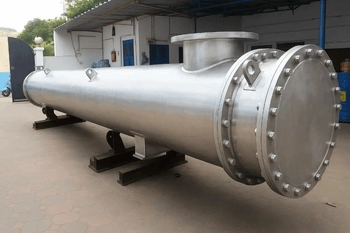
Oil-to-water — highest cooling capacity, lowest oil outlet temperatureA shell-and-tube heat exchanger in which hot transformer oil is pumped through the tube side and cooling water circulates on the shell side. The water-cooled design achieves oil outlet temperatures of 40–50°C — far lower than any air cooled alternative at the same ambient — making it the preferred choice for large transformers, high ambient locations, and applications where oil temperature must be tightly controlled.
- Higher pressure on the tube side prevents cooling water from becoming contaminated by hot transformer oil.
- Cooling water on shell side — supply at 28–35°C; return at 38–48°C
- U-tube or fixed tube sheet configuration — U-tube most common for OFWF transformer service
- Full leak detection provision — even a pinhole tube failure that allows oil into cooling water or water into oil requires immediate isolation
- All wetted materials verified compatible with transformer mineral oil
- Designed to ASME Section VIII; aligned with IEC 60076 thermal requirements
Forced Oil Forced Air Cooler (OFAF)
Air-cooled finned tube cooler with oil pump — no cooling water neededAn air cooled finned tube heat exchanger — transformer oil is pumped through tubes fitted with external aluminum fins, and axial flow fans force ambient air across the fin surface. The OFAF cooler package typically consists of multiple parallel cooler banks, each with its own fan, providing redundancy and modular capacity control. The entire cooling equipment is mounted either on a different skid next to the transformer or on the transformer tank.
- No cooling water required — ideal for outdoor substations and remote locations
- Aluminum fins on steel or stainless tubes — 9–11 FPI standard fin pitch
- Multiple parallel cooler banks — one, two, or three banks with independent fan control
- Oil outlet temperature: 55–70°C at 45°C design ambient (India)
- Auto-start of additional cooling banks on rising transformer oil temperature — tiered control
- Tank-mounted or skid-mounted configurations
Radiator-Type Oil Cooler (ONAN / ONAF)
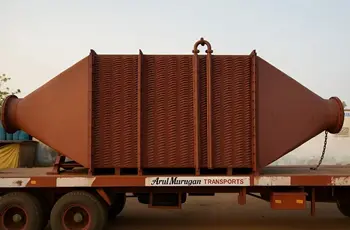
External corrugated radiator panels — small and medium transformer coolingBanks of corrugated steel radiator panels bolted to the transformer tank provide the cooling surface for ONAN and ONAF transformer cooling. In ONAN mode, the oil circulates by thermal convection and the radiator panels dissipate heat by natural air convection. In ONAF mode, fans are added to force air over the radiator panel surfaces, increasing the heat dissipation rate and the transformer's continuous rating.
- Corrugated steel or elliptical steel tube radiator panel design
- Bolted directly to transformer tank — no external oil piping or pump needed
- Fan addition for ONAF rating — fans clip to radiator bank frame
- Simple, reliable, no rotating equipment for ONAN operation
- Standard for distribution transformers and medium power transformers up to 50 MVA
Furnace Transformer Oil Cooler
High heat dissipation — furnace transformer and rectifier transformer serviceFurnace transformers — used to supply power to electric arc furnaces, induction furnaces, and aluminum electrolysis rectifiers — generate disproportionately high heat losses relative to their MVA rating because they operate at high current with significant impedance. Their oil coolers must handle substantially higher heat dissipation than equivalent-rated power transformers and are almost always OFWF shell-and-tube designs to achieve the lowest possible oil temperature.
- Very high heat dissipation per MVA — 3–6× that of equivalent power transformer rating
- OFWF shell-and-tube design — only water cooling can handle the heat load
- Multiple coolers in parallel for large furnace transformer installations
- Oil flow rates of 50–500 L/min depending on transformer size and heat dissipation
- Robust carbon steel construction for industrial foundry and steelmaking environments
- Complete with oil isolation valves, thermometers, flow indicators, and oil pump provision
Key Components — Transformer Oil Cooler
Shell
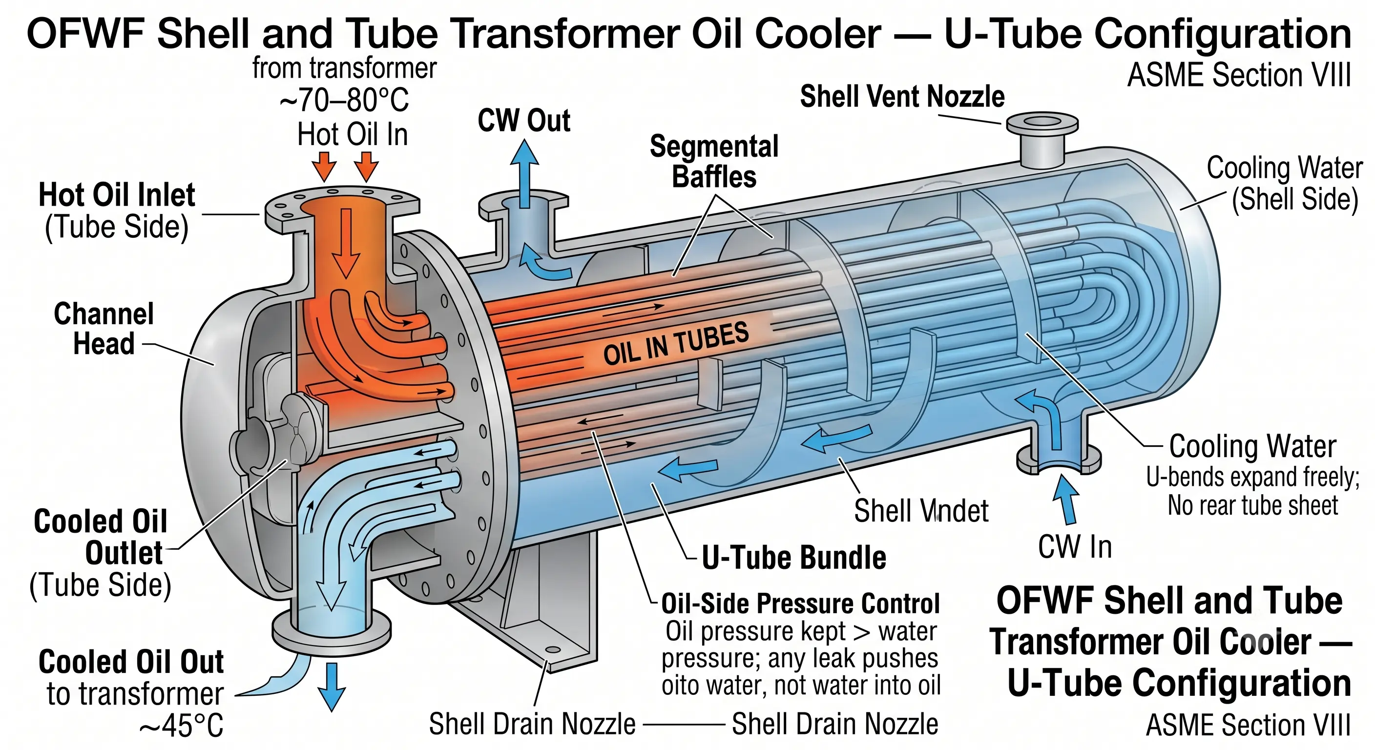
The outer cylindrical pressure vessel containing the tube bundle — carrying cooling water on the shell side. Carbon steel SA-516-70 is the standard shell material; 316L stainless where the cooling water is corrosive or treated with aggressive biocides. Shell nozzles for cooling water inlet, outlet, vent, and drain, with ASME B16.5 flanged connections.
Tube Bundle (Oil Side)
Seamless carbon steel or stainless steel tubes carrying the transformer oil at the higher pressure. U-tube configuration allows thermal expansion without a rear tube sheet, simplifying the design and eliminating thermal stress from the large temperature differential between incoming hot oil and the cooled oil at the return tube sheet. Tube material must be verified chemically compatible with transformer mineral oil.
Channel Head and Pass Partition
The flanged or welded enclosure at the oil inlet end — with a central pass partition directing hot oil into the first pass of U-tubes and collecting cooled oil from the return pass. Oil inlet and outlet nozzles are on this head, with flange ratings matched to the transformer oil circuit design pressure.
Baffles
Segmental baffles on the shell side guide cooling water in a cross-flow pattern across the tube bundle, increasing water-side velocity and turbulence — improving the shell-side heat transfer coefficient and ensuring effective use of the full tube surface area for oil cooling.
Oil Pressure Control — Safety Design
In a transformer oil cooler, oil contamination of the cooling water (or water ingress into the oil) is a critical failure mode. The cooler is designed with oil-side pressure maintained higher than water-side pressure — ensuring that any tube failure or joint leak pushes transformer oil into the cooling water circuit, not the reverse. Water ingress into the transformer oil is the more dangerous scenario as it drastically reduces the oil's dielectric strength.
Oil Isolation Valves, Vent, and Drain
Oil-side isolation valves allow the cooler to be isolated from the transformer oil circuit for maintenance or replacement without draining the transformer tank. Shell-side and tube-side vent connections at the highest points allow complete air purging; drain connections at the lowest points allow complete oil and water recovery during maintenance.
Engineering Advantages of Transformer Oil Coolers
Extends Transformer Insulation Life
Every degree of reduction in winding hotspot temperature doubles the remaining insulation life according to the Montsinger rule. A well-designed oil cooler that keeps the hotspot at 90°C rather than 98°C extends the 30-year design life by a meaningful margin — a direct return on the cooling system investment.
Enables Higher Continuous Rating
The same transformer core and winding design achieves a higher continuous MVA rating with effective forced oil cooling (OFAF or OFWF) than with natural convection (ONAN). Upgrading cooling equipment is one of the few ways to increase transformer rating without core or winding modification.
Reduces Transformer Physical Size
A transformer designed for OFWF cooling can use smaller, more compact windings for the same MVA rating — because the cooling system handles a higher heat flux per unit winding surface area. Smaller windings mean lower material cost, lighter weight, and easier transport and installation.
Lower Oil Temperature Improves Oil Quality
Transformer oil oxidation rate roughly doubles for every 10°C rise in temperature. Effective cooling keeps the bulk oil temperature well below 60°C in OFWF designs, dramatically slowing oil oxidation, acid formation, and sludge deposition — extending oil reconditioning intervals and reducing maintenance cost.
Compact Installation for OFWF
A water cooled shell-and-tube transformer oil cooler is extremely compact relative to its heat removal capacity — a cooler handling 500 kW of transformer losses occupies only a fraction of the space that an equivalent OFAF air cooled unit would need. This compactness is critical in indoor substations and industrial transformer installations.
Reduced Auxiliary Power for OFWF vs OFAF
The cooling water pump power for an OFWF cooler is significantly lower than the fan motor power for an OFAF cooler of equivalent thermal capacity in a hot climate — cooling water's far higher heat capacity per unit volume makes it a more energy-efficient cooling medium than air on a per-kW-removed basis.
Design Specifications and Standards
Transformer Oil Cooler: Standard Design Specifications for United Heat Exchangers
Material Selection
Material selection for a transformer oil cooler must satisfy three simultaneous requirements: compatibility with transformer mineral oil (no material that would contaminate or degrade the dielectric properties of the oil); adequate corrosion resistance against the cooling water chemistry; and the mechanical properties required by the ASME Section VIII design at the specified pressures.
| Component | Standard Material | Alternative Material | Reason for Alternative |
|---|---|---|---|
| Tubes (Oil Side) | SA-179 seamless carbon steel | SA-312 TP316L stainless | Corrosive or chemically treated cooling water on shell side; also when cooling water is on tube side |
| Shell | SA-516-70 carbon steel | SA-240 316L stainless | Aggressive cooling water chemistry; seawater cooling; industrial process water with high chloride |
| Tube Sheet | SA-516-70 carbon steel | 316L stainless; naval brass | Matching to tube material to avoid galvanic corrosion at tube-to-tube sheet joint |
| Channel Head | SA-516-70 carbon steel | SA-240 316L stainless | Where premium oil-side cleanliness is required; ester-based fluid compatibility |
| Gaskets | Non-asbestos compressed fiber | Spiral-wound SS/PTFE | Higher pressure class flanges; aggressive cooling water; premium leak tightness requirement |
Oil Compatibility Note: All materials in contact with transformer oil must be free of copper, zinc, and lead — these metals catalyze the oxidation of transformer mineral oil, accelerating its degradation and producing sludge that deposits on winding insulation. Carbon steel and stainless steel tube and shell materials are fully compatible with both mineral transformer oil and synthetic ester fluids. Before specifying any alternative tube or header material, confirm with the transformer manufacturer that the proposed metal is acceptable for the specific insulating fluid in service.
Applications and Transformer Types
| Transformer Type | Typical Rating | Cooling Class | Oil Cooler Type |
|---|---|---|---|
| Distribution Transformer | 100 kVA – 5 MVA, 11kV / 0.415kV | ONAN | Corrugated tank wall or bolt-on radiator panels — natural convection, no auxiliaries |
| Medium Power Transformer | 5 – 50 MVA, 33kV / 11kV | ONAN / ONAF | Radiator panel banks — natural oil, fans added for ONAF rating upgrade |
| Large Power Transformer | 50 – 500 MVA, 132kV / 400kV | OFAF or OFWF | OFAF: finned tube air cooler banks with oil pumps; OFWF: shell and tube oil-to-water cooler |
| Generator Step-Up Transformer (GSU) | 100 – 1,000 MVA, up to 765kV | OFAF / OFWF | Multiple parallel OFAF or OFWF cooler units for redundancy and tiered capacity control |
| Furnace Transformer (EAF / IF) | 10 – 150 MVA, high current | OFWF | Shell and tube oil-to-water cooler — only water cooling can handle the very high heat dissipation rate |
| Rectifier Transformer | 5 – 100 MVA, aluminum / chlor-alkali | OFWF | Shell and tube oil-to-water cooler — high harmonic losses require effective water cooling |
| Traction Transformer | 5 – 25 MVA, railway supply | OFAF | Compact forced oil forced air cooler skid alongside trackside substation transformer |
How to Select a Transformer Oil Cooler
Define Heat Dissipation
The total heat dissipation (kW or W) that the transformer oil cooler must remove is the sum of copper losses (I²R) at rated current and iron losses (core losses) at rated voltage — read directly from the transformer test report or nameplate data sheet. This is the fundamental thermal sizing input.
Specify Oil Flow Rate and Temperatures
Provide the oil flow rate (L/min or m³/hr) delivered by the transformer oil pump, the maximum oil inlet temperature (top oil temperature at rated load), and the target oil outlet temperature — the temperature at which cooled oil must return to the transformer to maintain winding hotspot within limits.
Choose Cooling Medium
OFWF (cooling water) for indoor installations, high ambient locations, compact installations, furnace and rectifier transformers, and wherever a low oil outlet temperature is required. OFAF (ambient air) for outdoor substations where cooling water is unavailable or unreliable. ONAN/ONAF radiator for distribution and medium power transformers.
Confirm Cooling Water Parameters (OFWF)
Specify cooling water supply temperature, return temperature limit, available flow rate, design pressure, and water quality (pH, hardness, chloride content) — these govern the shell material, tube material, and pressure rating selection for the shell-and-tube cooler.
Specify Mounting and Piping Interface
For replacement coolers — confirm existing oil nozzle sizes, orientations, and flange ratings. For new installations — specify preferred cooler mounting arrangement (tank-mounted, skid-mounted, or wall-mounted) and oil and water piping connection dimensions so that the cooler is designed for direct connection to your transformer without adaptor pipework.
Specify Instrumentation and Accessories
Confirm whether oil isolation valves, thermometers, oil and water pressure gauges, flow indicators, and differential pressure switches are required as part of the cooler supply — these items are typically built into the cooler assembly at the factory for a plug-and-play installation.
Maintenance Guide
Cooling Water-Side Scale Removal
Calcium carbonate scale from hard cooling water on the shell side progressively reduces heat transfer and eventually causes the oil outlet temperature to rise above the transformer temperature alarm setpoint. Circulate 5–10% inhibited citric acid through the shell side annually or at the first sign of rising oil outlet temperature — flush thoroughly before returning to service.
Leak Detection — Oil in Water or Water in Oil
Install an oil-in-water detector on the cooling water return line to give early warning of tube failure before oil contaminates the cooling water circuit. Similarly, inspect the oil for water content (Karl Fischer titration or crackle test) during routine oil sampling — even small water ingress into transformer oil requires immediate investigation and cooler isolation.
Oil-Side Tube Inspection
At the first opportunity during scheduled transformer outages, inspect the oil-side tube bore for fouling deposits — transformer oil in good condition leaves no deposits, but aged or oxidized oil can deposit varnish and sludge that reduces tube-side heat transfer. Hydraulic tube cleaning restores performance without tube bundle removal.
OFAF Fan and Drive Check
For OFAF transformer oil coolers, inspect fan blades, bearings, and motor annually — a failed fan can reduce cooling capacity sufficiently to cause transformer overtemperature on a hot day at peak load. Clean fin surfaces on OFAF coolers semi-annually in dusty or industrial environments.
Why United Heat Exchangers
All Transformer Cooler Types
Shell and tube OFWF, forced oil forced air OFAF, and radiator panel ONAN/ONAF designs — for all transformer MVA ranges and voltage classes from distribution to EHV transmission.
ASME U-Stamp Certified
All shell and tube transformer oil coolers fabricated to ASME Section VIII Division 1 with independent Authorized Inspector witness and full Manufacturer's Data Reports issued on every unit.
HTRI Thermal Design
Oil-side and water-side thermal performance verified by HTRI software — oil outlet temperature guarantee issued at the specified oil flow rate, heat dissipation, and cooling water inlet conditions.
Transformer OEM and Utility Experience
Transformer oil coolers supplied to both transformer manufacturers for new transformer packages and to power utilities as direct replacement coolers for ageing or failed units in service — with exact match to existing nozzle layout and dimensions.
Export to 30+ Countries
Transformer oil coolers supplied for power generation, transmission, and industrial transformer applications across the Middle East, Southeast Asia, Africa, and Europe — with ASME, IEC, and client-specified standards as required.
Oil Compatibility Assurance
All wetted materials verified compatible with mineral transformer oil and synthetic/natural ester fluids — no copper, zinc, or lead in any oil-wetted component. Material conformance certificate issued with every unit.
Get a Free Transformer Oil Cooler Quote in 48 Hours
Share your transformer type and MVA rating, heat dissipation (kW), oil flow rate, oil inlet and outlet temperatures, cooling medium (air or water), and cooling water parameters if applicable. Our team will complete the thermal sizing and deliver a full technical and commercial proposal within 48 hours.
Request My Free Quote →Delivery and What's Included
What's Included with Every Transformer Oil Cooler Order
- HTRI thermal performance documentation — oil outlet temperature at rated heat dissipation, oil flow rate, and specified cooling water or ambient air conditions; overdesign margin clearly stated
- ASME U-Stamp and Manufacturer's Data Report — for all shell-and-tube pressure-containing components; signed by Authorized Inspector; MAWP and design temperature on nameplate
- Oil compatibility certificate — material conformance statement confirming no copper, zinc, or lead in oil-wetted components; compatibility with mineral oil and ester fluids as specified
- Material certifications (MTRs) — traceable mill test reports for tube, shell plate, tube sheet, nozzle, and flange materials
- Hydrostatic test certificate — oil-side and water-side circuits each hydrotested at 1.5× design pressure; no leaks confirmed and witnessed
- Helium leak test option — for applications where the most sensitive leak detection is required before installation in the transformer oil circuit
- Certified general arrangement drawing — overall dimensions, nozzle schedule and orientations, mounting footprint, and connection details matched to your transformer interface
- Operations and maintenance manual — initial fill and vent procedure, shell-side descaling procedure, oil-side tube inspection guidance, leak detection method, and recommended maintenance intervals
- Lifetime technical support — thermal re-rating for changed load or ambient conditions, assessment of oil quality impact on cooler performance, and fitness-for-service review throughout the cooler's service life
Frequently Asked Questions — Transformer Oil Coolers
What is a transformer oil cooler?
A transformer oil cooler is a heat exchanger that removes the heat generated by electrical losses inside a power or distribution transformer by cooling the dielectric transformer oil that circulates between the transformer tank and the cooler. The transformer oil carries heat from the windings and core to the cooler, where it is rejected to either ambient air (OFAF) or cooling water (OFWF), and the cooled oil returns to the transformer tank to maintain winding and insulation temperatures within design limits.
What are the transformer cooling classes?
IEC 60076 defines four principal transformer cooling classes: ONAN (Oil Natural, Air Natural) — natural oil convection with radiator panels cooled by natural air; ONAF (Oil Natural, Air Forced) — natural oil convection with fans added to the radiator panels; OFAF (Oil Forced, Air Forced) — oil circulation pumps and dedicated finned tube coolers with forced air fans; and OFWF (Oil Forced, Water Forced) — oil circulation pumps with a shell-and-tube oil-to-water heat exchanger. Higher cooling classes allow a higher transformer continuous rating for the same winding design.
Why is the oil-side pressure kept higher than the water-side in an OFWF cooler?
In a shell-and-tube transformer oil cooler, the transformer oil pressure is deliberately maintained higher than the cooling water pressure. If a tube fails or a joint develops a leak, the higher oil pressure ensures that oil flows toward the water side rather than water flowing into the oil circuit. Water ingress into transformer oil — even in very small quantities (above approximately 30 ppm dissolved water) — drastically reduces the oil's dielectric strength and can precipitate insulation breakdown and transformer failure. Oil leaking into cooling water is the less dangerous scenario and is far easier to detect and manage.
What causes a transformer oil cooler to fail?
The most common causes of transformer oil cooler failure are: calcium carbonate scale buildup on the cooling water side (reducing heat transfer and causing oil temperature to rise); tube corrosion from aggressive or improperly treated cooling water (leading to pinhole tube leaks); tube fouling from aged or oxidized transformer oil depositing varnish inside tubes; and mechanical vibration fatigue at tube-to-tube sheet joints in transformers subject to significant vibration. Regular water-side descaling, cooling water quality monitoring, transformer oil sampling, and annual inspection address all four failure modes before they cause unplanned transformer outage.
Is it possible to produce a replacement transformer oil cooler that will work with an existing transformer?
Yes — United Heat Exchangers specializes in the manufacture of replacement transformer oil coolers to match the exact nozzle dimensions, flange ratings, overall envelope, and oil/water connection layout of the cooler being replaced. If you have the original fabrication drawing, we manufacture a direct replacement. If the drawing is unavailable, our engineers can work from photographs, field measurements, or the transformer nameplate data to specify a replacement that installs without modification to the transformer piping. Contact our team with your transformer MVA rating, heat dissipation, oil flow rate, and existing cooler dimensions for an assessment within 48 hours.
What is the maximum heat dissipation a single transformer oil cooler can handle?
United Heat Exchangers designs and fabricates transformer oil coolers handling heat dissipation from 10 kW (small distribution transformer auxiliary coolers) to over 5,000 kW in a single shell-and-tube unit. For very large power transformers (500 MVA and above) and large furnace transformers, multiple cooler units are installed in parallel — with each cooler on an independent oil circuit branch that can be isolated and serviced without taking the transformer offline, provided the remaining coolers maintain adequate thermal capacity during the maintenance period.
Author: Senthil Kumar, Technical Director — United Heat Exchangers Pvt. Ltd. | Last Updated: June 2026