Author: Senthil Kumar, Technical Director | Updated: May 2026
Table of Contents
- What Is a Stacked Heat Exchanger?
- The Two Meanings Engineers Use — Plate Stack vs Unit Stack
- How a Stacked Heat Exchanger Works
- Types of Stacked Heat Exchangers
- Key Components Explained
- Engineering Advantages of Stacked Configurations
- Flow Arrangements — Counter, Cross, and Parallel
- Design Specifications and Standards
- Material Selection Guide
- Industries and Applications
- Stacked vs Conventional Heat Exchangers
- How to Select a Stacked Heat Exchanger
- Maintenance Guide
- Why United Heat Exchangers
- Delivery and What's Included
- Frequently Asked Questions

What Is a Stacked Heat Exchanger?
A stacked heat exchanger maximizes heat transfer surface area within a minimum physical volume by layering multiple heat transfer surfaces — plates, fins, or complete shell-and-tube units — into a vertically or horizontally stacked configuration. The stacking arrangement delivers more thermal duty from less plot space than any equivalent non-stacked design.
Where conventional heat exchangers occupy large individual footprints, stacked designs consolidate multiple heat exchange functions onto a shared structure — reducing civil foundations, interconnecting pipework, and total installed cost while maintaining or exceeding the thermal performance of separate units.
As a leading stacked heat exchanger manufacturer in India, United Heat Exchangers designs and fabricates stacked plate, stacked shell-and-tube, and multi-unit stacked configurations for oil and gas, petrochemicals, power generation, HVAC, marine, and chemical industries — ASME certified, HTRI thermal rated, with full documentation on every unit.
The Two Meanings Engineers Use — Plate Stack vs Unit Stack
When engineers and procurement teams specify a "stacked heat exchanger," they mean one of two distinct configurations. Understanding which one applies to your duty is the starting point for every stacked heat exchanger enquiry.
Plate Stack Configuration
A small heat exchanger system with several plates laminated within one unitIndividual corrugated plates or fins are stacked in alternating layers within a single compact body. Each adjacent pair of plates forms a flow channel — hot fluid in every odd channel, cold fluid in every even channel. Adding more plates to the stack increases heat transfer surface area and thermal capacity without changing the external footprint of the unit.
- Applied in: plate heat exchangers, plate-fin exchangers, brazed plate units
- Surface area density up to 2,500 m² per m³ — much higher than shell and tube
- Capacity scalable by adding plates to the stack — no new frame or structure required
- Standard for HVAC, refrigeration, food and beverage, pharmaceutical
- Operating pressure: 1 to 100 bar depending on plate design and sealing method
Multi-Unit Stack Configuration
Multiple shells mounted on a common structure — refinery and process plant designTwo, three, or four complete shell-and-tube heat exchangers are mounted vertically on a common support structure with shared saddles, piping headers, and a single combined foundation. Each shell is a full TEMA-compliant heat exchanger — the stacking is an installation and civil engineering optimization rather than an internal plate arrangement.
- Applied in: crude oil preheat trains, process cooler banks, refinery heat recovery
- Reduces plot footprint by 50–70% vs the same units mounted individually
- Common foundation reduces civil and structural cost significantly
- Each shell independently maintained — individual bundle pull without disturbing adjacent units
- Standard for oil and gas refineries, petrochemical plants, offshore platforms
💡 Which configuration is right for your application? If you need a compact, high-efficiency heat exchanger for clean or moderate-fouling fluids at moderate pressure — plate stack. If you need to fit multiple high-pressure, fouling, or high-temperature shell-and-tube duties into a constrained plot — multi-unit stack. United Heat Exchangers engineers both configurations and recommends the correct one for your specific service in every proposal.
How a Stacked Heat Exchanger Works
The thermal operation of a stacked heat exchanger follows the same principle as any heat exchanger — two fluids exchange heat through a conductive surface without mixing. The stacked arrangement optimizes how that surface is packed into space.
Hot Fluid Distributes
Hot process fluid enters the inlet header or nozzle and distributes evenly across the full width of the stacked surface — every hot channel receives the same flow fraction.
Cold Fluid Enters Opposite
Cold fluid enters at the opposite end or port, filling every alternate channel. Hot and cold channels alternate throughout the stack — maximizing the shared heat transfer surface between both streams.
Boundary Layer Disruption
Corrugated or finned surfaces continuously disrupt the fluid boundary layer in each channel — generating turbulence that dramatically increases the local heat transfer coefficient compared to smooth-surface designs at equivalent velocities.
Heat Transfers Through Thin Walls
Between the hot channel and the nearby cold channel, thermal energy travels via the plate or fin wall, which is usually made of 0.4–1.2 mm aluminum or stainless steel. Thin walls and high-conductivity metals maximize heat transfer rate per unit of surface area.
Fluids Exit Separately
Cooled hot fluid collects at the outlet header and exits. Heated cold fluid exits through its own outlet port. The stacked arrangement keeps both streams fully separated throughout — zero cross-contamination by design.
Stack Scales to Duty
Additional plate layers or exchanger shells are added to the stack to increase total heat duty without expanding the external footprint — a scalability advantage that conventional designs cannot match without installing entirely new units.
Types of Stacked Heat Exchangers
Stacked Gasketed Plate Heat Exchanger
Corrugated plates — gasketed, fully disassemblableCorrugated stainless steel plates held between a fixed and movable frame with elastomeric gaskets forming the channel seals. Plates are stacked and clamped together. Adding plates to the stack increases heat transfer area — without replacing the frame — making this the most capacity-flexible stacked design.
- Fully disassemblable — each plate individually removed, cleaned, and replaced
- Capacity adjustable by adding plates without changing the frame
- Operating pressure: up to 25–30 bar limited by gasket seating
- Wide material range: 304/316L SS, duplex, titanium, Hastelloy
- Standard for HVAC, district heating, food and beverage, chemical process
Stacked Brazed Plate Heat Exchanger
Vacuum brazed stack — sealed, no frame, no gasketsCorrugated 316L stainless steel plates stacked and fused in a vacuum furnace using copper or nickel brazing filler — eliminating gaskets, frame, and bolts. The result is a sealed, compact block with the highest heat transfer surface density of any stacked plate configuration. Not field-disassemblable.
- No gaskets to replace — permanently sealed construction
- Highest surface area density — 90% smaller footprint than equivalent shell and tube
- Operating pressure: 30–45 bar copper brazed; 40–50 bar nickel brazed
- Nickel brazed mandatory for ammonia refrigerant — copper attacks rapidly
- Standard for HVAC chillers, heat pumps, refrigeration, and oil cooling
Stacked Plate-Fin Heat Exchanger
Corrugated fins between separator plates — cryogenic and multi-streamCorrugated fin inserts brazed between flat separator plates in a multi-layer stacked block. Different fin layers carry different fluid streams — allowing three or more process fluids to exchange heat simultaneously in one compact stacked block. Highest surface area density of all configurations.
- Surface density above 2,000 m² per m³ — highest of any heat exchanger type
- Multi-stream capability — up to 10+ fluid circuits in one stacked block
- Aluminum construction for cryogenic (-196°C); stainless for elevated temperature
- Standard for LNG liquefaction, air separation, and cryogenic gas processing
- Clean fluids only — not suitable for fouling services
Stacked Welded Plate Heat Exchanger
High pressure, high temperature — welded plate stackPlates are laser-welded together to eliminate gaskets on the process-side — allowing the stacked plate design to operate at pressures and temperatures beyond the limits of gasketed construction. Semi-welded variants retain partial disassembly capability for one-side cleaning access.
- Operating pressure: up to 40–100 bar — gasket-free construction removes pressure limit
- Operating temperature: up to 350°C — well above gasketed PHE elastomer limits
- Suitable for refrigerants, aggressive solvents, and acidic process streams
- Semi-welded variant allows cleaning on one side
- Used in chemical processing, ammonia, and high-temperature industrial duties
Multi-Unit Stacked Shell-and-Tube
Two to four shells on a common structure — refinery and process standardTwo, three, or four TEMA-compliant shell-and-tube heat exchangers are mounted vertically on shared saddles and a common structural steel support — with combined inlet and outlet piping headers reducing total connection count. Each shell operates independently and can be taken offline for maintenance without shutting the adjacent units.
- Reduces plot footprint by 50–70% vs individual mounting
- Shared foundation — significant civil cost saving on large installations
- Each shell: full TEMA-R/B/C compliance, ASME U-Stamp, independent maintenance
- Standard for crude preheat trains, process cooler banks, and reactor feed/effluent trains
- Operating conditions: full shell-and-tube design range — pressure to 350 bar, temperature to 650°C
Stacked Double-Pipe Heat Exchanger
Hairpin multi-tube stacked units — viscous and high pressureMultiple double-pipe (hairpin) heat exchanger sections stacked and connected in series or parallel on a common support frame. Each section is a tube-within-tube design — inner tube carries one fluid, the annular space carries the other. The stacked arrangement of multiple hairpin sections delivers the required heat duty in a compact vertical footprint.
- Ideal for high-viscosity fluids — each tube pair individually cleanable
- True counter-current flow in each section — highest thermal efficiency per unit
- Handles very high pressures — simple tube geometry rated to 400+ bar
- Used for small-flow, high-pressure, high-viscosity services in chemical plants
- Stacked sections add thermal capacity without increasing plot footprint
Key Components of a Stacked Heat Exchanger
Stacked Heat Exchanger — Both Configurations at a Glance
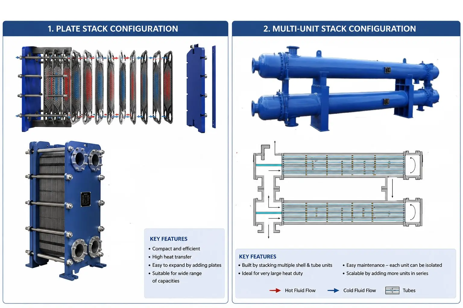
Left: Stacked plate configuration — 18 corrugated plates with alternating hot and cold channels. Right: Multi-unit shell-and-tube stack — two TEMA shells on shared saddles and one common foundation.
Heat Transfer Plates or Tubes
The primary thermal surface. In plate stacks: corrugated 316L stainless plates, 0.4–1.2 mm thick, pressed into herringbone or chevron pattern. In shell-and-tube stacks: straight TEMA tubes in carbon steel, stainless, or alloy — each shell independently sized for its specific process duty.
Stack Frame or Structural Support
In plate stacks: a bolted fixed-and-movable cover plate frame compresses the plate pack. In multi-unit stacks: a structural steel framework with shared saddles supports all exchanger shells and distributes combined dead load and thermal expansion forces to the common foundation below.
Common Inlet and Outlet Headers
In multi-unit stacked configurations, shared piping headers connect all shells to a single inlet and outlet nozzle per fluid circuit — reducing the total number of process pipe connections by 60–75% compared to individually mounted units. Header sizing ensures equal flow distribution across all stacked shells.
Shared Saddles and Supports
Saddle brackets positioned between stacked shells carry the weight of the upper shells and transfer loads to the structural frame. Saddle design must accommodate differential thermal expansion between shells — particularly critical when stacked shells operate at significantly different temperatures and use different tube materials.
Gaskets or Brazing Filler (Plate Stacks)
Elastomeric gaskets seal each plate channel in gasketed stacks — material selected per fluid chemistry and temperature. Copper or nickel brazing filler replaces gaskets in brazed plate stacks — creating a permanent, sealed metallurgical bond at every plate interface throughout the stack.
Differential Thermal Expansion Management
In multi-unit stacked shell-and-tube configurations, each shell may expand at a different rate due to different operating temperatures. Expansion loops, flexible saddle connections, or sliding support arrangements manage this differential without imposing mechanical stress on adjacent shells or the common structural frame.
Isolation Valves per Shell
Each shell in a multi-unit stack requires isolation valves on all four nozzles — allowing any single shell to be taken offline for maintenance without shutting the adjacent shells or the rest of the process. Valve accessibility from ground or platform level is designed into the stack layout at the engineering stage.
Access Platforms and Ladders
Multi-unit stacked shell-and-tube exchangers are by nature elevated — the top shell can be 3–6 meters above grade. Access platforms, ladders, and davit arms for channel cover removal are integral to a properly designed stack — specified alongside the exchanger, not as an afterthought during installation.
Engineering Advantages of Stacked Configurations
Stacking is not simply an aesthetic choice. Each advantage listed below represents a quantifiable engineering and commercial benefit that justifies the additional design and fabrication complexity of a stacked arrangement versus separate units.
Plot Space Reduction — 50 to 70%
Three stacked shells occupy the same plot footprint as one individually mounted shell. On offshore platforms, where structural steel and deck space cost thousands of dollars per square meter, this reduction delivers immediate and measurable capital savings — often recovering the entire cost of the stacked structure.
Single Foundation for Multiple Units
Instead of three separate civil foundations with independent anchor bolt patterns, one engineered foundation carries all stacked shells. Foundation cost reduction is typically 60–70% of what three separate foundations would cost — particularly significant on concrete platforms and in seismic design zones.
Reduced Total Pipe Connections
Shared headers reduce the total number of flanged pipe connections from 12 (four nozzles × three shells) to 4–6 connections on a common header. Fewer connections means fewer potential leak points, shorter installation time, less insulation, and lower total piping and inspection cost over the asset's life.
Higher Surface Area Density (Plate Stacks)
Stacked plate designs deliver 700–2,500 m² of heat transfer surface per m³ of unit volume — five to fifteen times the surface density of a shell-and-tube design. The same thermal duty is handled in a fraction of the physical space, enabling heat exchanger installation where shell-and-tube would be physically impossible.
Modular Capacity Scaling
Plate stacks add capacity by adding plates to the existing frame — without replacing the unit. Multi-unit stacks add capacity by installing a fourth shell on the existing structural steel — without civil work. Both allow capacity expansion with minimum downtime, minimum new capital, and no change to existing process connections.
Independent Maintenance Per Unit
In multi-unit stacks, each shell is isolated, depressurized, and maintained individually — without shutting adjacent shells or interrupting the process. This operational continuity advantage is the reason crude preheat trains and process cooler banks in refineries are almost always designed as stacked multi-unit arrangements.
Higher Thermal Effectiveness
Stacked plate designs operate closer to true counter-current flow than shell-and-tube designs — achieving thermal effectiveness of 85–95% versus 65–75% for equivalent shell-and-tube configurations. This means tighter temperature approaches, more heat recovered per unit of surface area, and lower total surface area required for a given duty.
Weight Reduction (Plate Stacks)
A stacked plate heat exchanger handling 1 MW of thermal duty weighs 80–90% less than an equivalent shell-and-tube unit. For weight-critical applications — offshore topsides, shipboard installation, elevated structures, and mobile plants — this weight saving directly reduces structural steel requirements and installed cost.
Flow Arrangements — Counter, Cross, and Parallel
The flow arrangement between hot and cold streams in a stacked heat exchanger determines its thermal effectiveness. Stacked designs can implement all three — and the choice affects the achievable temperature approach and required surface area.
| Flow Arrangement | Description | Thermal Effectiveness | Best Application |
|---|---|---|---|
| Counter-Current Flow | Hot and cold fluids flow in opposite directions through the stacked channels — hot enters where cold exits, and vice versa. Temperature difference between the two fluids is maintained along the entire stack length. | Highest — 85–95% thermal effectiveness. Enables temperature crossover — cold outlet can be warmer than hot outlet. | Heat recovery, close temperature approach duties, process-to-process heat exchange, economizer applications |
| Cross-Flow | One fluid flows longitudinally through the stacked channels; the other fluid flows perpendicular to the first — typically across the face of the stack. Common in air-cooled applications and plate-fin multi-stream designs. | ⚠ Moderate — 70–85% effectiveness depending on number of transfer units. Cannot achieve temperature crossover. | Air-cooled heat exchangers, gas-to-gas heat recovery, HVAC heat recovery coils, plate-fin multi-stream designs |
| Parallel Flow | Hot and cold fluids enter the stacked channels at the same end and exit at the same end — flowing in the same direction. Temperature difference decreases along the stack; minimum exit temperature difference limits heat recovery. | Lowest — typically 50–65% effectiveness. Temperature crossover is thermodynamically impossible. | Applications requiring controlled, gradual temperature change — sensitive process fluids, polymerization-prone streams, viscous fluid heating |
💡 Counter-current is almost always specified. For the same duty and surface area, a counter-current stacked heat exchanger delivers the highest thermal effectiveness and the tightest temperature approach. Unless there is a specific process reason to avoid temperature crossover — such as controlling reaction rate in a polymerization system — counter-current flow should be the default specification for any stacked heat exchanger duty.
Design Specifications and Standards
| Specification | Plate Stack Designs | Multi-Unit Shell-and-Tube Stack |
|---|---|---|
| Design Pressure | 1–25 bar (gasketed); 30–100 bar (welded / brazed plate) | Full vacuum to 350 bar — per individual TEMA shell design |
| Design Temperature | -160°C to +350°C depending on plate material and sealing | Cryogenic to +650°C — per shell material and TEMA class |
| Surface Area Density | 200–2,500 m² per m³ depending on plate and fin type | 30–60 m² per m³ — equivalent to individual shell-and-tube units |
| Thermal Effectiveness | 85–95% counter-current | 65–80% per TEMA design and pass arrangement |
| Number of Units in Stack | 10–700+ plates per frame | 2, 3, or 4 shells on one common structure |
| Plate / Tube Material | 304/316L SS, duplex 2205, titanium, Hastelloy C-276, aluminum | Carbon steel, SS, duplex, super duplex, titanium, CuNi, Hastelloy |
| Flow Arrangements | Counter-current, cross-flow, multi-pass | Counter-current, parallel, multi-pass per TEMA configuration |
| Design Codes | ASME Section VIII, PED, EN 13445, API 662 | TEMA-R/B/C, ASME Section VIII Div. 1 & 2, PED, IBR |
| NDE | Hydraulic pressure test; PMI for alloy plates | Radiography, UT, MPI, LPT, PMI — per TEMA class and ASME code |
| Thermal Rating | HTRI Xchanger Suite — written performance guarantee | HTRI Xchanger Suite — written performance guarantee |
Material Selection Guide
Material selection in stacked heat exchangers serves the same criteria as any heat exchanger — fluid chemistry, temperature, fouling nature, and required service life. The stacked arrangement does not change material selection criteria but it does concentrate multiple fluid duties into one structural unit, which sometimes requires different materials in adjacent shells or plate sections.
Carbon Steel
Standard for multi-unit stacked shell-and-tube designs in non-corrosive hydrocarbon service. Most cost-effective material for refinery preheat trains where crude oil contacts the tube interior. Corrosion allowance of 1.5–3 mm specified per fluid. Not suitable for stacked plate designs — too brittle for thin plate pressing.
316L Stainless Steel
Standard plate material for stacked plate heat exchangers in general process, chemical, food and beverage, and pharmaceutical service. Low carbon grade prevents sensitization at plate edges. Suitable for mild chloride environments and acidic aqueous solutions. Not suitable for direct seawater or high-chloride brine contact.
Duplex 2205 Stainless
Specified for stacked heat exchangers handling seawater, produced water, or chloride-containing process streams where 316L would suffer stress corrosion cracking. Twice the yield strength of 316L allows thinner plates at the same pressure rating. Standard for offshore and marine stacked plate installations.
Titanium Grade 1 / 2
The definitive material for seawater-service stacked plate heat exchangers — immune to chloride pitting and crevice corrosion at all marine temperatures. Weight advantage over CuNi for offshore applications. Standard specification for offshore and desalination stacked plate coolers where seawater is the cooling medium.
Aluminum (Plate-Fin Stacks)
Standard construction material for stacked plate-fin heat exchangers in cryogenic service — LNG liquefaction, air separation, and gas processing cold boxes. Excellent cryogenic toughness and very high thermal conductivity. Not suitable for aqueous or alkaline environments — cryogenic and hydrocarbon service only.
Hastelloy C-276
Specified for stacked heat exchangers handling aggressive chemical streams — concentrated acids, mixed oxidizing-reducing environments, wet chlorine, and process fluids that defeat standard stainless steels. High cost justified for high-value chemical services where material failure is commercially unacceptable.
Industries and Applications
| Industry | Stacked Heat Exchanger Application | Configuration Specified | Reason for Stacking |
|---|---|---|---|
| Oil & Gas Refining | Crude oil preheat trains, process cooler banks, atmospheric and vacuum distillation overhead condensers | Multi-unit stacked shell-and-tube — 2 to 4 TEMA shells per stack, common structure | Refinery plot space is expensive and constrained — stacking 3 shells into one structure frees adjacent plot for other units and reduces total civil foundation cost by 60–70% |
| Offshore Platforms | Process coolers, gas compression cooling, produced water coolers, seawater cooling circuits | Stacked titanium plate heat exchangers for seawater; stacked shell-and-tube for process cooling | Offshore deck space costs $10,000–$50,000+ per m² installed. Every m² of plot area saved by stacking delivers direct capital and structural weight savings |
| HVAC — District Cooling | District cooling heat interface units, chiller evaporators and condensers, building-side hydraulic isolation | Stacked gasketed plate heat exchangers — 316L or titanium plates depending on fluid quality | District cooling plant rooms and substation buildings have strict space budgets. Stacked plate PHEs deliver full cooling capacity in 1/5th the space of shell-and-tube alternatives |
| Power Generation | Closed cooling water heat exchangers, lube oil coolers, hydrogen coolers, condensate polishing heat exchangers | Stacked plate PHE for clean utility cooling; stacked shell-and-tube for process and steam duties | Power plant auxiliary systems contain dozens of heat exchangers competing for plant room space. Stacking consolidates multiple cooling duties onto fewer structural supports |
| Chemical Processing | Reactor feed-product heat recovery, solvent coolers and heaters, multi-stage heat recovery trains | Stacked welded or semi-welded plate for aggressive chemicals; stacked shell-and-tube for high-pressure duties | Multi-stage heat recovery in complex chemical processes requires multiple heat exchange steps — stacking consolidates them into a compact, accessible unit with shared piping infrastructure |
| LNG and Gas Processing | LNG liquefaction train cool boxes, air separation cold boxes, and natural gas dew point regulation | Stacked aluminum plate-fin — multi-stream configuration handling 3–10 simultaneous fluid circuits | Cryogenic cold boxes are insulated pressure vessels — every additional unit requires a larger, heavier insulated box. Stacking all cryogenic duties into one multi-stream plate-fin block minimizes the cold box size and insulation cost |
| Marine and Shipbuilding | Engine central coolers, jacket water coolers, gear oil coolers, HVAC sea water coolers | Stacked titanium or CuNi plate heat exchangers — compact, light, seawater-compatible | Engine room space on vessels is among the most constrained in any industrial application. Stacked plate heat exchangers replace multiple shell-and-tube units with a single compact unit per cooling duty |
| Food and Beverage | Multi-stage pasteurization, heating, holding, and cooling in continuous food processing lines | Stacked gasketed plate — multiple plate sections with different temperature stages in one frame | Food processing lines require multiple precise temperature stages in sequence — a single multi-section stacked plate PHE handles all stages in one hygienic, CIP-cleanable unit |
Stacked Heat Exchangers for Every Industry — Maximum Duty, Minimum Space
Plate stack or multi-unit shell-and-tube — custom engineered, ASME certified, HTRI thermal guaranteed. From Coimbatore, India to refineries, platforms, and plants worldwide. Free quote in 48 hours.
Request My Free Quote →Stacked vs Conventional Heat Exchangers — Engineering Comparison
| Criterion | Stacked Plate Design | Stacked Multi-Unit Shell-and-Tube | Individual Shell-and-Tube Units |
|---|---|---|---|
| Plot Footprint | Smallest — 80–90% less than equivalent shell-and-tube | 50–70% less than individual units of same duty | Largest total footprint |
| Thermal Effectiveness | Highest — 85–95% counter-current | Standard — 65–80% per TEMA design | Standard — 65–80% |
| Fouling Service | Moderate fouling only — clean and CIP cleanable services | Full fouling service — mechanical tube cleaning accessible | Full fouling service — bundle pull, tube rodding |
| Operating Pressure | ⚠ Limited by plate design — up to 100 bar welded plate | Full TEMA range — up to 350 bar per shell design | Full TEMA range — up to 350 bar |
| Civil and Foundation Cost | Minimum — self-supporting compact unit | One foundation for multiple shells — 60–70% saving | Separate foundations per shell — highest civil cost |
| Capacity Scalability | Add plates to frame — no structural work | Add shell to structure — minimal civil work | Install entirely new unit — full civil and piping work |
| Independent Maintenance | Entire unit offline for plate cleaning | Each shell isolated independently while others operate | Each unit independently isolated |
| Weight | Lightest — 80–90% weight saving vs shell-and-tube | ⚠ Similar to individual shells — structural steel adds weight | ⚠ Heaviest total weight for equivalent duty |
How to Select the Right Stacked Heat Exchanger
Determine the Configuration Type
Is the duty a single heat exchange service needing compact design? → Plate stack. Is the duty multiple separate shell-and-tube services that need to co-locate on a constrained plot? → Multi-unit stack. This choice is made before any thermal sizing begins.
Assess Operating Pressure and Temperature
Gasketed or brazed plate stacks below 30 bar and below 200°C. 30–100 bar or above 200°C — welded plate stack. Above 100 bar or above 350°C — multi-unit shell-and-tube stack is the only option. Pressure and temperature define the boundary between plate and shell-and-tube stacked designs.
Evaluate Fouling Severity
Clean or lightly fouling fluids — plate stack with CIP capability. Moderate fouling that needs periodic mechanical plate cleaning — gasketed plate stack only. Heavy fouling requiring tube rodding or bundle pull — multi-unit shell-and-tube stack. Fouling service dictates whether mechanical cleaning access is mandatory.
Define the Plot Area Budget
Quantify the available plot area in meters squared and the maximum unit height permitted by overhead obstructions or structural constraints. Stacked configurations free adjacent plot but are taller — confirm that the height gained by stacking fits within head room or structural clearance limits at the installation site.
Confirm Fluid Compatibility
For plate stacks: verify that both fluids are compatible with the plate material, gasket material (if gasketed), and brazing filler (if brazed). For multi-unit stacks: each shell can have independent material specifications — stacking does not require all shells to use the same materials or handle the same fluid.
Plan Access and Maintenance from Day One
Stacked designs are tall. Confirm maintenance access requirements — channel cover removal clearance, bundle pull length for shell-and-tube stacks, plate pack access width for plate stacks — before finalizing the structural height and orientation. Maintenance access designed in at the start costs nothing. Retrofitting it costs significantly more.
Maintenance Guide — Stacked Heat Exchanger Service
| Task | Applies To | Frequency | Action |
|---|---|---|---|
| Thermal Performance Monitoring | All types | Continuous — log approach ΔT daily | Track hot and cold outlet temperatures against baseline values at the same flow rates. A rising approach temperature signals fouling inside the exchanger — act before performance loss affects the downstream process |
| CIP Chemical Cleaning | Plate stacks | When approach ΔT rises 15% above baseline | Circulate approved cleaning solution — dilute nitric or citric acid for mineral scale; alkaline detergent for organic or biological fouling. Follow the manufacturer's specified concentration and contact time. Flush fully with clean water before returning to service |
| Plate Mechanical Cleaning | Gasketed plate stacks only | When CIP cleaning is insufficient — typically every 2–5 years | Loosen compression bolts, separate plate pack, brush or pressure-wash each plate face, inspect gasket seats, replace damaged gaskets, reassemble to manufacturer's specified compression dimension. Record new compression dimension as the next maintenance baseline |
| Individual Shell Isolation and Inspection | Multi-unit shell-and-tube stacks | At each turnaround — one shell per outage cycle on a rotating basis | Shut off isolation valves, vent, drain, and depressurize the chosen shell. Remove channel cover and withdraw tube bundle for inspection. Check tube wall thickness by UT, tube-to-tube-sheet joint condition, baffle condition. Clean tubes mechanically or by high-pressure water jet before returning to service |
| Saddle and Structure Inspection | Multi-unit shell-and-tube stacks | Annual | Inspect shared saddle brackets, structural steel frame members, and anchor bolts for corrosion, cracking, or displacement. Check that sliding saddle connections move freely — seized sliding saddles impose thermal expansion loads on the shell nozzles and connected piping |
| Nozzle and Flange Inspection | All types | Annual — during scheduled turnaround | Inspect all inlet and outlet nozzle flanges and gaskets for leakage, corrosion, and flange face condition. Tighten or replace bolts and gaskets as needed. Pay particular attention to common header connections on multi-unit stacks — header joints see the combined flow and are subject to fatigue from flow-induced vibration |
| Access Platform Inspection | Multi-unit shell-and-tube stacks | Annual | Check all access platforms, handrails, ladders, and grating for corrosion damage, bolt loosening, and structural integrity. Elevated platforms on stacked configurations are part of the pressure equipment maintenance access system — deterioration compromises safe maintenance access |
💡 Rotate maintenance across the stacked shells. In a 3-shell stack, inspect Shell 1 at Turnaround Year 1, Shell 2 at Year 2, and Shell 3 at Year 3. This distributes maintenance labor evenly, keeps the other two shells operational during each inspection, and ensures every shell is inspected every 3 years without a single shutdown affecting total heat recovery capacity by more than 33%.
Why United Heat Exchangers for Stacked Heat Exchangers
Designing a stacked heat exchanger that performs correctly requires simultaneous expertise in thermal design, structural engineering, and fabrication tolerances for stacked loads. A thermal design error in a plate stack wastes surface area. A structural design error in a multi-unit shell-and-tube stack creates differential expansion loads that damage nozzles, flanges, or connected piping. United Heat Exchangers applies all three disciplines to every stacked heat exchanger we design.
35+ Years Manufacturing Both Configuration Types
Plate stacks and multi-unit shell-and-tube stacks are both core product lines. Deep fabrication knowledge of both designs — applied to every order, not just the most recent ones.
HTRI Thermal Rating — Written Guarantee
Every stacked heat exchanger is thermally rated using HTRI Xchanger Suite at your specified flow, fouling, and temperature conditions. We issue a written thermal performance guarantee — not an estimate.
ASME U-Stamp and TEMA Compliance
All pressure-rated stacked units are manufactured to ASME BPVC Section VIII. Multi-unit shell-and-tube stacks are designed to TEMA-R, B, or C as required. U-Stamp MDR issued with every applicable unit.
Integrated Structural Design
We design the stacked structure, shared saddles, differential expansion provisions, and access platforms as an integrated package — not as an afterthought. Structural calculations and access drawings issued with every multi-unit stack order.
Complete Documentation
MTRs, hydrostatic test certificates, TEMA data sheets, structural drawings, thermal performance guarantee, and ASME MDR — issued as a complete package before shipment. No follow-up requests.
Export Ready — Global Markets
Stacked heat exchangers supplied to refineries, offshore platforms, and process plants across the Middle East, Southeast Asia, Europe, and Australia. ASME certification satisfies registration requirements in all major markets.
Delivery and What's Included
What's Included with Every Stacked Heat Exchanger Order
- Written HTRI thermal performance guarantee — both circuits rated at your specified fluid conditions, fouling resistances, and flow rates
- ASME U-Stamp Manufacturer's Data Report — signed by Authorized Inspector for all pressure-rated stacked units
- Material certifications (MTRs) — traceable mill test reports for all pressure-containing components in every shell or plate
- Hydrostatic test certificates — both circuits pressure-tested to 1.5× design pressure with independent test records
- Structural design calculation — shared saddle sizing, combined dead load analysis, differential thermal expansion assessment, and wind/seismic load calculation for multi-unit stacks
- General arrangement drawing — overall dimensions, nozzle orientation, saddle spacing, access platform layout, and bundle pull clearance for multi-unit stacks
- TEMA data sheet (shell-and-tube stacks) — fully completed per TEMA standard format for each shell in the stack
- Operation and maintenance manual — individual shell isolation procedure, plate cleaning procedure, saddle inspection guide, maintenance rotation schedule, and spare parts list
- Lifetime technical support — thermal re-rating, plate count change, shell addition to existing stack, and performance troubleshooting throughout service life
Get a Free Stacked Heat Exchanger Quote in 48 Hours
Share your configuration type (plate stack or multi-unit shell-and-tube), fluid details, flow rates, temperatures, design pressure, plot area constraint, and any fouling or cleaning requirements. Our engineering team selects the right stack type, sizes it, and delivers a full technical proposal within 48 hours.
Request My Free Quote →Frequently Asked Questions — Stacked Heat Exchangers
What is a stacked heat exchanger?
A stacked heat exchanger maximizes heat transfer capacity within a minimum physical volume by layering multiple heat transfer surfaces — corrugated plates, fins, or complete shell-and-tube units — into a stacked configuration. Compared to any comparable non-stacked design, this provides higher thermal duty from less plot space. The term covers both plate-stack compact heat exchangers and multi-unit shell-and-tube configurations mounted on a common structure.
What is the difference between a stacked plate heat exchanger and a stacked shell-and-tube heat exchanger?
A stacked plate heat exchanger has multiple corrugated metal plates layered within a single compact unit — the plates themselves form the stack. A stacked shell-and-tube heat exchanger has two or more separate TEMA-compliant shells mounted vertically on a common structural support with shared saddles, common piping headers, and one foundation — the stacking is an installation arrangement, not an internal plate configuration.
How much plot space does a stacked heat exchanger save?
Stacked plate heat exchangers occupy 80–90% less plot area than equivalent shell-and-tube units for the same heat duty. Multi-unit stacked shell-and-tube configurations reduce total plot footprint by 50–70% versus individually mounted units of the same duty. For offshore platforms where deck space costs $10,000–$50,000+ per m², this represents major capital cost savings in addition to the operational benefits.
Can a stacked heat exchanger handle fouling fluids?
It depends on the configuration. Stacked plate designs in gasketed construction can handle moderate fouling — plates are removed and mechanically cleaned during maintenance. Brazed or welded plate stacks are limited to clean or CIP-cleanable fluids. Multi-unit stacked shell-and-tube exchangers handle heavy fouling fluids fully — each shell allows complete bundle pull and mechanical tube cleaning independently of the adjacent shells.
Can individual shells in a multi-unit stacked configuration be maintained independently?
Yes — this is one of the primary operational advantages of the multi-unit stacked configuration. Each shell has its own isolation valves on all four nozzles. Any single shell can be depressurized, drained, and taken offline for maintenance while the adjacent shells continue in service. This allows a rotating maintenance schedule across a 3-shell stack — one shell inspected per turnaround — with only a one-third reduction in total heat recovery capacity during each maintenance period.
What is the maximum number of shells that can be stacked?
Practical limits are typically 3 or 4 shells in a vertical stack for shell-and-tube designs — beyond four shells the structural height creates access difficulties, wind loading challenges, and foundation complexity that outweigh the plot space saving. For plate stacks, 700+ plates in a single frame are achievable — the stacking of individual plates within one frame has no practical limit beyond the compression bolt length and frame structural capacity.
How does differential thermal expansion affect a multi-unit stacked shell-and-tube exchanger?
When stacked shells operate at different temperatures, they expand by different amounts — creating differential expansion forces on the shared saddle connections and common structural frame. This is managed by designing one fixed saddle per shell with one or more sliding saddles that allow the shell to expand axially without applying axial loads to the frame. Correct saddle design is one of the most technically demanding aspects of multi-unit stacked shell-and-tube design — United Heat Exchangers provides structural calculations for every multi-unit stack.
What is the delivery time for a stacked heat exchanger from United Heat Exchangers?
Standard stacked plate heat exchangers in gasketed or brazed configuration deliver in 4–8 weeks from order confirmation. Multi-unit stacked shell-and-tube configurations, welded plate stacks, alloy constructions, and ASME-stamped designs deliver in 10–20 weeks. Expedited schedules for refinery turnaround and platform replacement projects are available on request — contact our engineering team with your timeline for confirmation.
Author: Senthil Kumar, Technical Director — United Heat Exchangers Pvt. Ltd. | Last Updated: May 2026