Author: Senthil Kumar, Technical Director | Updated: June 2026
Table of Contents
- What Is an Air Cooled Heat Exchanger?
- How Do Air-Cooled Heat Exchangers Operate?
- Key Components of an Air Cooled Heat Exchanger
- Tube Bundle Construction — Tubes, Headers, and Frames
- Fin Types Explained — Extruded, Embedded, and Wrap-On
- Header Types — Plug, Cover Plate, and Pipe & U-Bend
- Axial Flow Fans — Selection and Design Rules
- Plenum, Mechanical Drive, and Structure
- Forced Draft vs Induced Draft — Detailed Comparison
- Thermal Design Fundamentals
- Typical Heat Transfer Coefficients
- Performance Control Methods
- Noise Control and Viscous Liquid Design
- Advantages of Air Cooled Heat Exchangers
- Industries and Applications
- Why United Heat Exchangers
- Delivery and What's Included
- Frequently Asked Questions

What Is an Air Cooled Heat Exchanger?
An air cooled heat exchanger (ACHE), also called an air fin cooler or fin fan cooler, is process equipment that removes heat from a hot fluid by passing ambient air straight through a bundle of tubes with fins on the outside. No cooling water, no cooling tower, no intermediate medium: the atmosphere itself is the coolant.
That single distinction separates the technology from every water-cooled alternative. A shell-and-tube exchanger backed by a wet cooling tower transfers heat to water first, then to air at the tower. An ACHE collapses that two-stage path into one — ambient air contacts the finned surface directly, and the heat is gone.
The working principle is straightforward: process fluid flows through the tube side; an axial-flow fan, either forced-draft (fan below the bundle) or induced-draft (fan above), drives or draws air across the fin surface; heat transfers through the tube wall and fin into the airstream and dissipates to atmosphere. Fin geometry — typically helical or embedded fins on carbon steel, alloy steel, or stainless tubes — multiplies the external surface area by a factor of 15 to 20 over a bare tube, making up for the low heat transfer coefficient of air.
United Heat Exchangers designs and manufactures air cooled heat exchangers in India to API 661 and ASME Section VIII, serving oil and gas, refinery, petrochemical, and power generation clients across export markets.
How Do Air-Cooled Heat Exchangers Operate?
Every air cooled heat exchanger, regardless of size or configuration, operates on the same underlying heat transfer relationship that governs all recuperative heat exchangers — the Fourier equation. At one end of the tube bundle, the hot process fluid enters a box header, is split up among several finned tubes, and travels through the bundle in one or more passes (changing direction at the opposite header before returning), and exits the outlet header at a lower temperature. Simultaneously, ambient air — driven by one or more axial flow fans — flows essentially unmixed in the vertical direction across the outside of the bundle, picking up the heat rejected through the tube wall and fins, and is discharged to atmosphere at an elevated temperature.
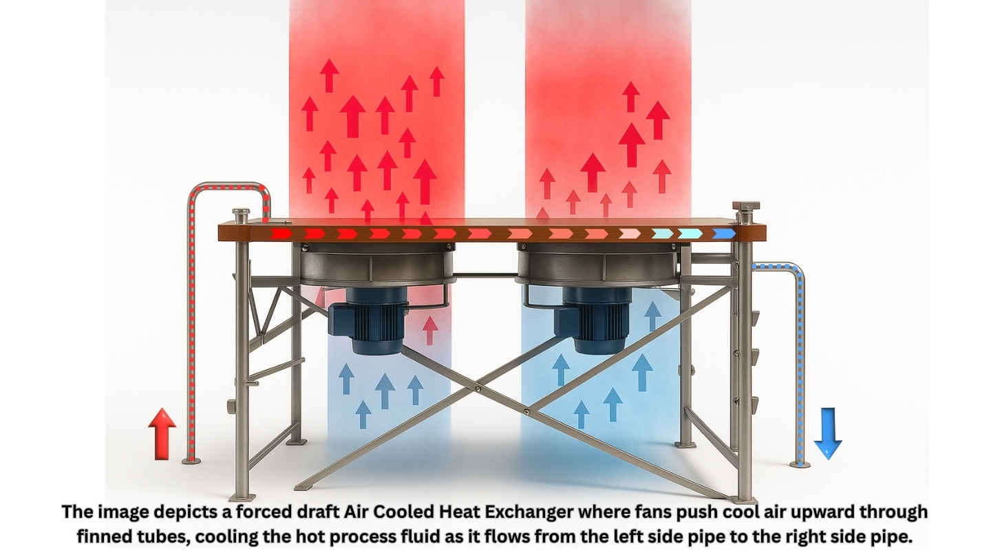
Hot Fluid Enters Header
Process fluid enters the inlet box header and is distributed across the tubes connected to that pass.
Flow Through Finned Tubes
Fluid travels the length of the bundle inside finned tubes, transferring heat through the tube wall to the fins.
Direction Reversal at Pass Partition
Internal pass partitions in the header turn the flow back through the next row of tubes — building a near-countercurrent pattern.
Air Crosses the Bundle
Axial flow fans drive ambient air vertically across the finned surface — substantially unmixed from row to row.
Cooled Fluid Exits / Warm Air Discharges
Process fluid leaves the outlet nozzle at the design outlet temperature; warmed air discharges to atmosphere.
Engineering Insight — The Fourier Equation and the MTD Correction Factor: The basic sizing relation for an air cooled heat exchanger is Q = U × A × CMTD, where Q is the heat duty, U is the overall heat transfer coefficient referred to the bare tube area A, and CMTD is the corrected mean temperature difference. CMTD is calculated as CMTD = F × LMTD, where LMTD is the conventional log mean temperature difference between the two fluids and F is a correction factor that accounts for the fact that an air cooled heat exchanger is a cross-flow exchanger, not a true counter-current one. The air flows substantially unmixed upward across the bundle while the process fluid is routed back and forth (and generally downward overall) through the tube passes. With a single pass, F can be significantly less than 1.0; as the number of tube-side passes increases to four or more, the flow arrangement approaches true counter-current behavior and F approaches 1.0. Getting the pass arrangement right — and therefore F right — is one of the first decisions in air cooled heat exchanger thermal design.
Key Components of an Air Cooled Heat Exchanger
Every air cooled heat exchanger is built from the same set of functional building blocks, whether it is a small single-bay unit or a multi-fan refinery condenser. Understanding these components — and how forced draft and induced draft units arrange them differently — is the foundation for understanding everything else about ACHE design.
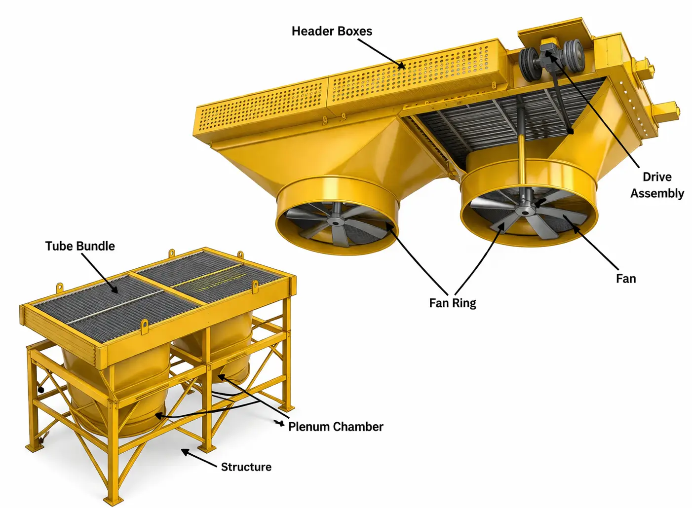
Typical Components of an Air Cooled Heat Exchanger — Induced Draft (top) and Forced Draft (bottom)

Tube Bundle (or Bundles)
One or more bundles of finned tube heat transfer surface form the core of the unit — discussed in full detail in the next section. A single bay may contain several bundles of the same or different services sharing one set of fans.
Air-Moving Device
Almost always an axial flow propeller-type fan; occasionally a centrifugal blower for ducted applications, or no mechanical device at all in a natural draft tower where buoyancy alone moves the air.
Driver and Power Transmission
Unless the unit is natural draft, a motor (almost always electric) drives the fan through a speed-reducing transmission — a belt drive for small and medium fans, or a gearbox for large fans and high-power motors.
Plenum Chamber
An enclosure between the bundle and the fan that smooths and distributes airflow — box type or slope-sided, with the slope-sided form generally giving the best air distribution over the bundle face.
Support Structure
Columns, braces, and cross beams that elevate the unit high enough above grade for air to enter at a reasonable approach velocity — frequently a pipe rack in refineries and chemical plants, with other equipment housed beneath.
Maintenance Walkways and Ladders (Optional)
Platforms at header and fan deck level with ladder access to grade — standard on larger units to allow safe routine inspection, fan pitch adjustment, and header maintenance.
Louvers (Optional)
Adjustable blades above the bundle that restrict airflow for outlet temperature control — covered in detail in the performance control section.
Recirculation Ducts and Chambers (Optional)
Ductwork that routes a portion of warm discharge air back to the fan intake — used to protect high pour-point or freeze-prone fluids in cold weather.
Variable Pitch Fan Hub (Optional)
A hub mechanism that automatically changes blade pitch angle in response to a temperature or pressure signal — providing both process temperature control and significant fan power savings.
Tube Bundle Construction — Tubes, Headers, and Frames
Building Plug and Cover Plate Headers for Tube Bundles
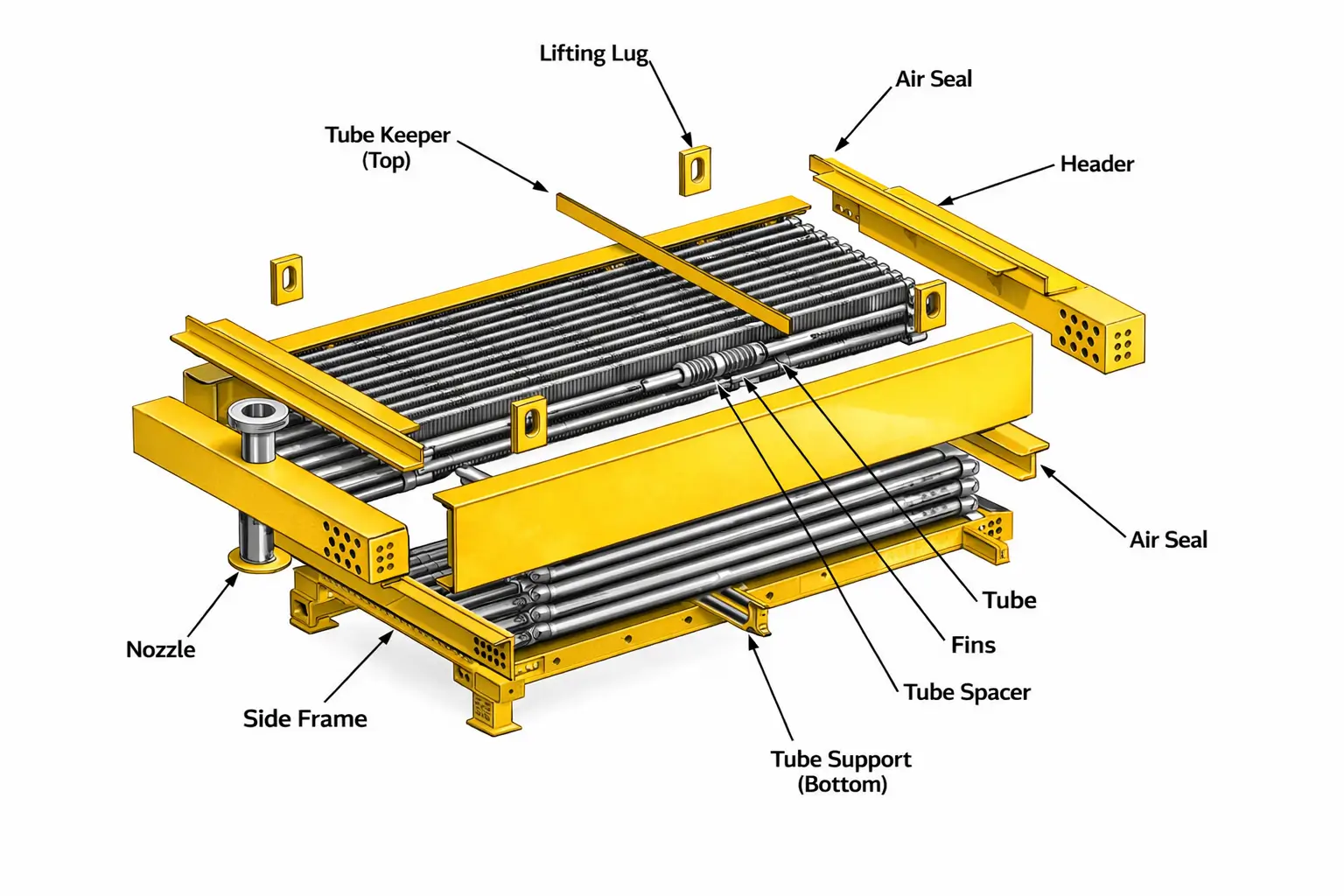
The tube bundle is the single most important assembly in an air cooled heat exchanger — it is the heat transfer surface itself, and everything else in the unit exists to move air across it or to support and connect it. A tube bundle is an assembly of finned tubes, a pair of box headers (one at each end), side frames, and internal tube supports that hold the tubes in place along their length and maintain the correct spacing for airflow.
The prime (bare) tube is the pressure-containing element and is selected in any metal suitable for the process — carbon steel, stainless steel, duplex, titanium, or higher alloys — based on corrosion, pressure, and temperature considerations exactly as for any other pressure part. The fins, almost always aluminium for their combination of thermal conductivity and ease of fabrication, are added to the outside of this prime tube to compensate for the inherently low heat transfer coefficient of air at atmospheric pressure and at the modest velocities needed to keep fan power reasonable. Steel fins are used in place of aluminum only for very high temperature applications where aluminum would be unsuitable.
Bundles are rectangular and are almost always arranged with tubes on a triangular pitch, typically between 2 and 2.5 tube diameters — this pitch governs how many tubes fit across the bundle width and, together with the fin geometry, sets the net free area available for air to pass through (typically around half of the bundle's projected face area). A bundle commonly contains 2 to 10 rows of tubes counted in the direction of airflow, though depths up to 30 rows are used for unusual services such as bare-tube viscous liquid coolers. Most bundles are mounted horizontally with air entering from below and discharging upward; vertical bundle arrangements with horizontal airflow exist in natural draft towers, where bundles line the periphery of the tower base. "A-frame" or "V-frame" arrangements — angling two bundles together over a single fan set — saving plot area at the expense of increased fan power for a given task and decreased performance when airflow is restricted by wind on exposed faces.

Tube Sheet
The thick plate at each end of the bundle into which the tubes are rolled or welded — the primary pressure boundary between the tube-side fluid and the header box interior.
Plug Sheet / Cover Plate
The removable or plugged face of the header box opposite the tube sheet — either a welded plate with threaded plugs opposite each tube (plug header) or a bolted, gasketed removable plate (cover plate header).
Top, Bottom, and End Plates
The remaining four sides of the rectangular header box, welded to the tube sheet and plug sheet/cover plate to form a sealed pressure vessel that distributes fluid to the tubes.
Pass Partitions and Stiffeners
Internal welded plates that divide the header into separate compartments — establishing the tube-side flow pattern (the number of passes) and generating velocities close to true counter-current for the best mean temperature difference. Stiffeners are partitions with flow openings that also serve as structural stays.
Side Frames
structural components that link the two headers, run the length of the bundle on either side, and serve as mounting places for tube supports as well as for lifting and installing the bundle.
Tube Spacers and Support Cross-Members
Internal components positioned along the bundle length that maintain correct tube-to-tube spacing and prevent sag or vibration of the long, finned tubes between the headers.
Tube Keepers
Retaining devices that lock individual tubes in position within the support cross-members, preventing axial movement under thermal cycling while still permitting individual tube removal for replacement.
Vents, Drains, and Instrument Connections
Small nozzles on the header for venting trapped vapour during filling, draining liquid for maintenance or freeze protection, and connecting pressure or temperature instrumentation for process monitoring and control.
Design Note — Differential Thermal Expansion: In services with a large temperature drop across a single pass, the tubes on the hot end of a pass expand significantly more than those that have already given up most of their heat. Where this differential expansion would overstress the header, a horizontally split header design is used — dividing the header box into separate compartments at different elevations so that each group of tubes can expand independently without distorting the header structure.
Fin Types Explained — Extruded, Embedded, and Wrap-On
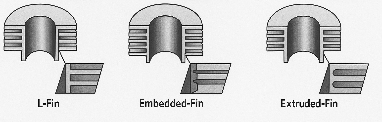
The method used to attach aluminium fins to the bare tube is one of the most consequential decisions in air cooled heat exchanger specification — it determines not just the initial heat transfer performance, but how predictably that performance holds up over decades of service, and how well the prime tube is protected from atmospheric corrosion. Three attachment methods dominate the industry, each with a distinct cost, temperature limit, and long-term performance profile.
| Fin Type | Attachment Method | Maximum Service Temperature | Long-Term Performance |
|---|---|---|---|
| Extruded Fin | An aluminium sleeve is extruded directly from — and integrally bonded to — the base tube along its entire length, forming a single monolithic tube-and-fin structure | Up to approximately 600°F (315°C) | Best available protection of the prime tube from atmospheric corrosion; consistent, predictable heat transfer from initial installation through the life of the cooler |
| Embedded Fin | An aluminum strip is helically wound and embedded into a pre-cut helical groove in the tube wall, with the groove edges peened back over the fin foot to lock it tightly in place | Above 600°F up to approximately 750°F (315°C – 400°C) | Continued predictable heat transfer over the cooler's life — the recommended fin type for the entire temperature band above the extruded fin's limit |
| Wrap-On (L-Foot) Fin | An aluminum strip is wrapped helically onto the tube under tension, with a foot formed at its base as it is wound on, mechanically gripping the tube surface | Below approximately 250°F (120°C) | Economical for moderate temperatures, but the fin-to-tube bond can loosen over time as the assembly cycles thermally — heat transfer should be derated to allow for this gradual loss of contact |
Beyond the attachment method, fin geometry itself is standardized across the industry into a fairly narrow band of practical options. Fins are most commonly helical, spaced at 7 to 11 fins per inch, between 5/16 inch and 1 inch high, and 0.010 to 0.035 inch thick. Combined with the base tube diameter, these dimensions produce the 7:1 to 25:1 ratio of extended-to-prime surface area mentioned earlier — the higher ratios coming from taller, more closely spaced fins on smaller-diameter tubes.
Engineering Insight — Serrated Fins: Plain helical fins present a continuous, smooth surface to the airstream. Cutting serrations across the fin height interrupts this surface, breaking up the air boundary layer and increasing turbulence. At the expense of a slight rise in air-side pressure drop and, consequently, fan horsepower, the outcome is a quantifiable increase in the air-side heat transfer coefficient. Serrated fins are a useful tool when bundle face area is constrained and the air-side film coefficient is the controlling resistance, but they are avoided in dusty or lint-laden environments where the serrations can trap particulate and progressively block the fin pitch.
Header Types — Plug, Cover Plate, and Pipe & U-Bend
The header is the pressure box at each end of the tube bundle that distributes the process fluid into the tubes and collects it after each pass. Three header configurations cover essentially all air cooled heat exchanger services, and the choice between them is driven primarily by the fouling tendency of the process fluid and the pressure/size combination of the unit.
Plug Header
Welded box header — individual tube access via threaded plugsThe header box is fully welded, with the plug sheet drilled and threaded directly opposite every tube end. A threaded plug seals each hole. To inspect, clean, or plug a tube, the relevant plug is simply unscrewed — the rest of the header remains sealed and in service.
- No gasketed joint to maintain — fully welded construction
- Individual tube access for mechanical cleaning, hydro-jetting, or plugging
- The default header type for the great majority of refinery and gas plant services
- Pass partitions and stiffeners welded inside to set the flow pattern
Cover Plate Header
Bolted, gasketed removable face — full simultaneous tube accessInstead of a welded plug sheet, the header face is a removable cover plate, bolted on with a gasket. Removing the cover exposes every tube end at once — the preferred configuration for severe fouling services where cleaning one tube at a time through plugs is impractical.
- Fastest, most complete access for heavily fouling tube-side fluids
- Requires a gasketed joint — must be re-sealed correctly after every opening
- Internal pass partitions and stiffeners as for the plug header
- Generally specified where downtime for full-face cleaning is acceptable in exchange for thoroughness
Pipe and U-Bend Header
No box header — tubes connected directly by pipe and U-bendsRather than terminating in a box header, the finned tubes are connected to each other and to the process piping by pipe sections and U-bends, forming a continuous serpentine flow path. There is no header box pressure boundary to design or maintain.
- Eliminates the header box as a separate pressure component
- Common for high-pressure services, small bundles, and serpentine-coil viscous fluid coolers
- Tube-side access for cleaning is more limited than with plug or cover plate headers
- Often paired with bare (unfinned) tubes in viscous or fouling liquid service
Axial Flow Fans — Selection and Design Rules
The axial flow, propeller-type fan is the air-moving heart of almost every air cooled heat exchanger — pushing air across the bundle in a forced draft arrangement, or pulling it across in an induced draft arrangement. Fans range from about 3 feet to 60 feet in diameter and can have anywhere from 2 to 20 blades, made from wood, steel, aluminum, or fiberglass-reinforced plastic, either solid or hollow. The most efficient blade designs have an airfoil cross-section with a wide chord near the hub that tapers to a narrower chord at the tip, combined with a built-in twist — this taper and twist compensate for the lower rotational velocity near the hub compared with the tip, producing a much more uniform velocity profile across the swept area than a simple flat blade would.
Blades may have a fixed pitch angle or an adjustable pitch angle; fixed pitch is generally limited to small fan diameters (below about 5 feet), while the great majority of air cooled heat exchangers use adjustable pitch fans. Adjustable pitch comes in two forms: manually adjustable, where the pitch angle is set with the fan stopped and remains fixed until next adjusted, and automatically (or "auto-variable") adjustable, where the pitch changes continuously while the fan is running — typically via a pneumatically actuated diaphragm inside the hub working against return springs, driven by a process temperature or pressure signal.
To provide redundancy against a mechanical failure, and to give a simple two-step capacity control (one fan running, or both), a bundle or set of bundles is usually served by two fans rather than one. Even, predictable air distribution across the bundle face is essential for the thermal design to be reliable in practice, and this is governed by a small set of proportioning rules developed from decades of field experience.
Fan Coverage ≥ 40% of Face Area
The projected area swept by the fan blades should be at least 40% of the projected face area of the tube bundle it serves, ensuring the fan's influence reaches across the full bundle width.
Bundle Resistance ≥ 3.5× Fan Ring Velocity Pressure
The static pressure loss through the bundle should be at least 3.5 times the velocity pressure loss through the fan ring — this resistance ratio is what forces the air to spread out and cover the bundle evenly rather than short-circuiting near the fan.
Tube Length / Bundle Width Ratio of 3 – 3.5
For a two-fan bay, keeping the ratio of tube length to bundle width in the range of 3 to 3.5 — together with a minimum of 4 tube rows and roughly 50% net free area — generally satisfies both proportioning rules above without further checking.
Minimum 4 Tube Rows
Bundles thinner than about 4 rows in the airflow direction struggle to present enough resistance relative to the fan ring, undermining even air distribution — 4 rows is treated as a practical lower limit for most services.
Net Free Area ≈ 50% of Face Area
With standard tube pitch (2 – 2.5 tube diameters) and fin geometry, roughly half of the bundle's projected face area remains open for air to pass through — the other half is occupied by tubes and fins.
Fan Tip Speed Limit ≈ 12,000 ft/min
For mechanical reliability, fan blade tip speed is generally kept at or below about 12,000 feet per minute (roughly 61 m/s) — and is often reduced further than this purely to achieve lower noise levels.
Plenum, Mechanical Drive, and Structure
Three remaining subsystems complete the air cooled heat exchanger: the plenum chamber that connects the fan to the bundle aerodynamically, the mechanical drive train that turns the fan, and the structural frame that supports the entire assembly at the correct elevation.
Box-Type Plenum
A simple rectangular enclosure between the fan ring and the bundle. Straightforward to build and to mount machinery on — the standard choice for forced draft units, where the drive assembly is supported from the plenum structure itself.
Slope-Sided Plenum
A tapering enclosure that transitions more gradually between the fan ring diameter and the bundle face dimensions, giving the best air distribution of the two plenum types. It is used almost exclusively on induced draft units, because hanging a heavy machinery mount from a sloped forced-draft plenum presents significant structural difficulties.
Electric Motor
By far the dominant fan driver across the industry. Hydraulic motors are used in the rare case where electrical power is unavailable at the site — they also provide inherent variable-speed capability, but at relatively low efficiency compared with an electric motor and VFD.
Belt Drives — Timing Belt and V-Belt
High-torque positive-drive timing belts running on toothed sprockets are the most popular speed reduction method for motors up to roughly 50–60 horsepower and fans up to about 18 feet in diameter. Conventional banded V-belts remain common for small to medium fans.
Gear Drives
For very large motors and fan diameters beyond the practical range of belt drives, right-angle gear reducers are used instead — selected to deliver the correct fan speed from the motor's running speed via an appropriate reduction ratio.
Variable Frequency Drives (VFDs)
Motor and fan speed can also be controlled directly with a VFD — an increasingly common alternative or complement to mechanical pitch-change mechanisms for both temperature control and power saving.
Columns, Braces, and Cross Beams
The structural frame elevates the exchanger to a height sufficient for the necessary volume of air to enter underneath at an approach velocity low enough not to impede fan performance, and high enough to discourage recirculation of discharged hot air back into the inlet.
Pipe Rack Mounting
To conserve ground space in refineries and chemical plants, air cooled heat exchangers are very often mounted above and supported by a pipe rack, with other equipment occupying the space underneath — a highly efficient use of the plot.
Design Loads
The structure is built to withstand all of the loads that it will encounter while in use, including dead load (the equipment itself), live load (maintenance staff and equipment), wind load, earthquake load, snow load when relevant, and reaction loads imposed by associated pipework.
Forced Draft vs Induced Draft — Detailed Comparison
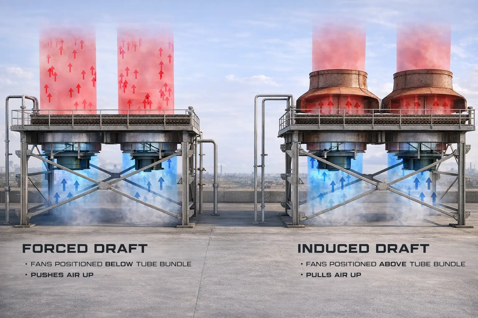
Whether to place the fans below the bundle (forced draft, pushing air up) or above the bundle (induced draft, pulling air up) is one of the earliest and most consequential decisions in air cooled heat exchanger selection. Both arrangements use exactly the same tube bundle technology — the difference lies entirely in fan position and the resulting plenum geometry, and each brings a distinct set of advantages and limitations.
| Consideration | Induced Draft (fan above bundle) | Forced Draft (fan below bundle) |
|---|---|---|
| Air Distribution | Generally more uniform across the bundle face | Generally less uniform than induced draft |
| Hot Air Recirculation | Lower risk — hot exhaust air discharges upward at roughly 2.5 times the intake velocity (around 1,500 ft/min), carrying it well clear of the inlet | Higher risk — lower bundle discharge velocity and higher fan-ring intake velocity, with no stack effect to help carry exhaust away |
| Weather Protection / Process Stability | Better — the plenum covers roughly 60% of the bundle face, shielding it from direct sun, rain, and hail and giving steadier process control | Lower — the finned tubes are fully exposed to sun, rain, and hail, which can affect process stability |
| Behavior on Fan Failure | Greater residual capacity — the natural "stack" effect of the plenum above the hot bundle is significant even with the fan stopped | Lower natural draft capability if the fan stops, since there is no stack above the bundle |
| Fan Horsepower for Very Hot Effluent Air | Potentially higher — fan horsepower for a given mass flow increases as the air handled becomes hotter (less dense) | Potentially lower for the same case, since fan horsepower varies inversely with the absolute temperature of the air the fan is handling |
| Maintenance Access | Fans and drives are less accessible, and maintenance may need to be carried out in the warm air rising naturally from the bundle below | Better access to fans and upper bearings for routine maintenance |
| Bundle Replacement | The plenum must be removed before a bundle can be taken out | Better access for bundle replacement, with the plenum structure not in the way |
| Effluent Air Temperature Limit | Effluent air temperature is generally limited to around 220°F (≈104°C) to protect fan blades, bearings, and other mechanical equipment sitting directly in the hot air stream | Not subject to the same exhaust-temperature limit on the mechanical equipment, since the drive sits below the bundle in cooler inlet air |
Engineering Insight — Choosing Between the Two: In the majority of services, the advantages of induced draft — better air distribution, lower recirculation risk, and better weather protection and process stability — outweigh its disadvantages, making it the more common default choice. The key exception is high process inlet temperature: when the process inlet temperature exceeds roughly 350°F (≈175°C), forced draft is generally favored, because an induced draft unit could expose its fan, bearings, and other mechanical equipment to effluent air above the ~220°F protective limit during fan-off or low-airflow conditions — for example on a hot day with the fan stopped for maintenance or load reduction.
Thermal Design Fundamentals
Thermal design of an air cooled heat exchanger involves more interacting variables than a comparable shell-and-tube exchanger. A shell-and-tube unit has a fixed cooling-water inlet temperature and flow rate to design against; an ACHE must be designed against an ambient air temperature that varies continuously through the day and across the seasons, and — unlike the cooling water flow rate, which is normally fixed by the cooling tower system — the air flow rate and the resulting air outlet temperature are themselves design variables that the engineer chooses by selecting the number of tube rows, the face area, and the fan size. Because tube diameter, fin geometry, tube pitch, number of rows, number of passes, tube length, bundle width, and the air flow rate can all be varied independently, many different bundle geometries can satisfy a given duty — but only one (or a small family of them) will represent the best balance of capital cost, fan power running cost, and noise.
Engineering Insight — Two Ways to Find the Minimum Heat Capacity Rate: The effectiveness-NTU method used for ACHE thermal design relies on identifying which stream — the tube-side process fluid or the air — has the smaller heat capacity rate (mass flow rate × specific heat), denoted Cmin, and which has the larger, Cmax. Their ratio R = Cmin / Cmax and the number of transfer units Ntu = A · U / Cmin together determine the exchanger's thermal effectiveness E — the percentage of the actual maximum heat transfer that is possible. At the design stage, the air mass flow rate is not yet known, so it is not obvious in advance whether the air or the tube-side fluid will turn out to be the Cmin stream; ACHE design methods such as the Kays & London Ntu approach handle both possibilities and converge on a consistent bundle face area, number of rows, and air outlet temperature.
A practical first-pass sizing approach uses a dimensionless grouping that combines the temperature parameter Z (essentially the ratio of the tube-side temperature change to the maximum possible temperature change, T1 − t1) with the assumed overall heat transfer coefficient U, in the form Z × 100 / U. This grouping correlates strongly with two of the most important first-estimate decisions in ACHE design: how many tube rows the bundle should have, and what standard air face velocity to design for. As a rough guide, smaller values of this grouping point toward shallower bundles (around 4 rows) at higher face velocities, while larger values point toward deeper bundles (8 to 10 rows or more) at correspondingly lower face velocities — reflecting the trade-off between adding more heat transfer rows versus moving more air per row.
Once a trial bundle geometry has been selected on this basis, the Ntu and R values for that geometry are calculated and checked against effectiveness charts for the chosen number of tube-side passes (one-pass cross-flow, two-pass, three-pass, or four-or-more-pass approximating true counter-current flow). This check yields the predicted air outlet temperature and confirms whether the trial geometry meets the required duty. The selection is then verified rigorously against empirical heat transfer and pressure drop correlations — refined over decades of testing and field observation — before being finalized as the basis for fabrication.
Typical Heat Transfer Coefficients
For preliminary sizing — before a rigorous HTRI or equivalent thermal rating is performed — experienced ACHE designers rely on published ranges of overall heat transfer coefficient (U), referred to the bare tube outside surface, for broad categories of service. These figures assume a typical finned tube construction (1-inch OD tube with around 10 plain extruded aluminium fins per inch, 5/8 inch high, giving roughly a 21:1 extended-to-prime surface ratio) and are intended purely for first estimates, to be confirmed by detailed rating.
| Service Category | Typical Fluid / Condition | Indicative U (Btu/hr·ft²·°F) |
|---|---|---|
| Condensing Service | Steam (0 – 20 psig) | 135 – 200 |
| Ammonia | 105 – 125 | |
| Amine reactivator overhead | 100 – 120 | |
| Light hydrocarbons | 95 – 105 | |
| Light naphtha | 80 – 100 | |
| Reactor effluent (reforming-type units) | 80 – 100 | |
| Gas Cooling Service | Hydrocarbon gas, 250 – 1,500 psig (ΔP ≈ 5 psi) | 70 – 90 |
| Hydrocarbon gas, 50 – 250 psig (ΔP ≈ 3 psi) | 50 – 60 | |
| Air or flue gas, 50 – 100 psig (ΔP ≈ 1 – 5 psi) | 10 – 30 | |
| Liquid Cooling Service | Engine jacket water / process water | 120 – 155 |
| Light hydrocarbon liquids | 90 – 120 | |
| Light gas oil | 70 – 90 | |
| Hydroformer / reformer liquids | ≈ 85 | |
| Fuel oil | 20 – 30 | |
| Residuum / tar | 5 – 20 |
Performance Control Methods
Air cooled heat exchangers are designed for a maximum ambient air temperature, but ambient temperature varies continuously — through the day, and through the seasons. Some form of capacity control is therefore essential, both to avoid over-cooling the process (which can be just as detrimental as under-cooling for some fluids) and to save fan power when the full design air flow is not needed. While by-passing some of the process fluid around the exchanger is technically possible, controlling the air flow is by far the more common approach.
Adjustable Louvers
Louvers above the bundle create an adjustable restriction to airflow. They are simple and effective for temperature control, but because they work by adding resistance, they do not save fan power when airflow is reduced — and even fully open, a louver imposes a small permanent pressure loss and energy penalty.
Two-Speed Motors and VFDs
Unlike louvers, reducing fan speed — whether in discrete steps with a two-speed motor or continuously with a variable frequency drive — genuinely reduces the power the fan consumes when full airflow is not required, since fan power varies with roughly the cube of fan speed.
Sequential Fan Shutdown
On multi-fan units, simply switching individual fans off in sequence as ambient temperature falls gives a coarse but effective and very reliable form of capacity step-down, particularly useful as a backstop alongside finer control methods on the remaining fans.
Auto-Variable Pitch Fans
Fans whose blade pitch angle adjusts automatically and continuously while running — typically via a pneumatic diaphragm acting against internal springs in the hub — driven by a temperature or pressure signal from the outlet header. In temperate climates, auto-variable pitch fans can save a large share of design fan power over a year, often paying back their additional cost within about a year.
Internal Recirculation
One fixed-pitch fan blowing upward is paired with one auto-variable pitch fan capable of negative pitch — able to blow air downward. By running the variable fan in reverse, warm air can be drawn back across the coldest part of the bundle to temper it and prevent freezing, while in hot weather both fans simply blow upward as normal.
External Recirculation
Practical only on forced draft units: hot exhaust air leaving the bundle enters a top plenum covered by a louver. An average temperature sensor beneath the bundle regulates the louvre position and, consequently, the temperature of the blended intake air. When this louvre is partially closed, some hot air is diverted down a duct back to the fan intake, where it mixes with cold ambient air.
Co-Current Flow Arrangement
For high pour-point fluids, arranging the tube-side flow co-currently with the air (rather than counter-currently) ensures the hottest process fluid contacts the coldest incoming air, while the coolest, most viscosity-sensitive process fluid contacts air that has already been warmed — keeping the tube wall temperature high where it matters most for flow stability.
Auxiliary Heating Coils (Steam or Glycol)
A heating coil placed directly beneath the bundle, combined with a closed louver above, can warm or maintain the bundle temperature during shutdown in freezing weather, preventing the contents from solidifying — and can also be used to temper very cold incoming air while the fan runs and the exhaust louver remains open.
Noise Control and Viscous Liquid Design
Noise Control
Industrial noise regulation has increasingly turned attention toward air cooled heat exchangers, particularly as quieter solutions have addressed louder equipment elsewhere on site. ACHE noise originates predominantly from fan blade vortex shedding and general air turbulence, with the speed reducer (especially high-torque belt drives or gears) and the motor as secondary, generally broad-band, contributors — occasionally with narrow-band tones from interaction between the drive and the structure.
Engineering Insight — Why Bigger, Slower Fans Are Quieter: For efficient fans operating at moderate tip speeds, ACHE noise is approximately proportional to the cube of the fan blade tip speed and to the first power of the fan horsepower consumed. Because the cube relationship dominates, a relatively modest reduction in tip speed — achieved by using a larger-diameter, slower-turning fan to move the same air volume — produces a disproportionately large noise reduction. With this principle applied, it is generally practical and economical to bring the sound pressure level at 3 feet from the unit down to about 85 dB(A). Below roughly 70 dB(A), however, noise from the gearbox and motor themselves begins to dominate the total, and further reduction requires specific measures aimed at the drive train rather than the fan.
Design Considerations for Viscous Liquids
Cooling viscous liquids in an air cooled heat exchanger raises a fundamentally different design problem from cooling a low-viscosity liquid or a gas. Inside the tube, laminar-flow film coefficients are of the same low order of magnitude as the air-side film coefficient on a bare tube — meaning that adding fins to increase the air-side surface area gives little overall benefit, because the laminar tube-side resistance dominates regardless. For this reason, bare tube bundles with a relatively large number of rows are the norm for genuinely viscous services.
Where the outlet viscosity remains moderate — up to roughly 20 centipoise — designers can often keep the tube-side flow turbulent (Reynolds number above the critical value of about 2,000) by using larger-diameter tubes and higher velocities, up to around 10 ft/sec. This typically comes with a significant pressure drop penalty, often in the range of 30 to 100 psi, but this is normally economically justified: the resulting increase in pump capital and operating cost is small compared with the reduction in exchanger cost that comes from designing for turbulent rather than laminar flow.
| Flow Regime | Pressure Drop Sensitivity | Heat Transfer Sensitivity | Stability Implication |
|---|---|---|---|
| Turbulent | Weak function of viscosity, strong function of mass velocity | Heat transfer coefficient falls noticeably as flow slows and viscosity rises | Self-correcting — a cooler, more viscous tube only needs a slight flow reduction to match the pressure drop of its neighbors, and its reduced heat transfer limits further over-cooling |
| Laminar | Strong function of viscosity, weak function of mass velocity | Heat transfer coefficient is essentially independent of viscosity and only weakly dependent on mass velocity | Not self-correcting — a cooler, more viscous tube must slow dramatically to match pressure drop, but this barely reduces its heat transfer, so it keeps cooling (and thickening) further, tending toward instability |
This instability is the central problem with laminar flow in ACHE tube bundles: because imperfect air-side distribution (from wind effects, or simply from having multiple tube rows per pass) inevitably means some tubes run cooler than others, laminar flow allows those cooler tubes to progressively slow down and thicken further until they are nearly stagnant, while the remaining tubes carry most of the flow — producing the combination of high pressure drop and poor overall performance. The practical countermeasures are to limit bundles to no more than one row per pass with at least two passes per row (so fluid is remixed between passes), and — for fluids with both high viscosity and a high pour point — to split the cooling range into stages, handling the final low-temperature stage in a dedicated bare-tube serpentine coil or a closed-loop tempered water system, itself cooled by a separate ACHE. For viscous but otherwise clean fluids such as lubricating oil, turbulence promoters — typically simple swirl strips, a flat metal strip twisted into a helix and inserted in the tube — can increase the tube-side heat transfer coefficient four- to ten-fold at a lower velocity than would otherwise be needed, with a pressure drop that rises only modestly with mass velocity, making non-isothermal flow far more stable.
Advantages of Air Cooled Heat Exchangers
Site Location Independence
Because the cooling medium is the surrounding air rather than a body of water, an air cooled heat exchanger can be installed virtually anywhere — inland, offshore, in deserts, or at remote pipeline locations — without any dependence on a river, sea, well, or municipal water supply.
No Cooling Water System Required
Eliminating the cooling water loop also eliminates the cooling tower, circulating water pumps, water treatment chemicals, blowdown disposal, and the ongoing risk management associated with waterborne fouling and biological growth.
Simple, Robust Mechanical Construction
The tube bundle itself has no internal baffles, floating heads, or shell-side gaskets — it is fundamentally a simple array of finned tubes between two headers, which is mechanically robust, straightforward to inspect, and tolerant of process upsets.
Scalable Across an Enormous Size Range
The same basic technology — finned tube bundles, axial flow fans, plenums, and structural frames — scales from a single small fan serving a compact unit up to dozens of large multi-fan bays serving a major power plant condenser, simply by adding bundles and bays.
Flexible Performance Control
A wide toolkit of control methods — louvers, two-speed motors, VFDs, auto-variable pitch fans, internal and external recirculation, and auxiliary heating coils — allows a single design to handle everything from hot summer days to sub-zero winter nights without overcooling or freezing.
Modular Capacity Expansion
Additional fan bays, upgraded motors and drives, or a switch from fixed to auto-variable pitch fans can often increase capacity on an existing structural frame without replacing the tube bundles themselves — a much lower-cost expansion path than replacing a water-cooled exchanger.
Reduced Environmental Footprint
With no cooling water intake, no blowdown discharge, and no chemical dosing for water treatment, an air cooled heat exchanger avoids the thermal discharge and effluent permitting concerns that come with water-cooled systems.
Decades of Proven Field Experience
The fin types, header types, fan design rules, and performance correlations used in air cooled heat exchanger design today have been refined over many decades of testing and field observation across the process and power industries — this is a thoroughly mature, well-understood technology.
Industries and Applications
Air cooled heat exchangers are installed wherever a process or utility stream needs to be cooled or condensed without relying on a cooling water system. United Heat Exchangers designs and supplies air fin coolers and fin fan coolers across the following industries and duty types.
| Industry | Typical ACHE Duty | Process Stream | Typical Configuration |
|---|---|---|---|
| Petroleum Refining | Crude/vacuum overhead condensers, product coolers, reactor effluent coolers | Crude overhead vapor, naphtha, kerosene, gas oil, reformer effluent | Plug header, induced or forced draft depending on inlet temperature |
| Gas Compression | Inter-stage and after-stage coolers | Compressed natural gas, process gas, instrument air, nitrogen | Plug header, auto-variable pitch fans for outlet temperature control |
| Natural Gas Processing | Amine and glycol coolers, residue gas coolers | Lean/rich amine, glycol, NGL, residue gas | Plug or cover plate header depending on fouling tendency |
| Petrochemical | Overhead condensers, product coolers | Olefins, aromatics, styrene, methanol | Cover plate header for fouling services; induced draft for close approach |
| Power Generation | Steam turbine exhaust condensers, lube oil coolers | LP steam, turbine lube and seal oil | Large multi-bay induced draft condenser banks |
| Fertilizer | Ammonia and CO₂ coolers | Ammonia, urea melt, CO₂ | Stainless or duplex tube bundles for corrosive streams |
| Offshore & Marine | Wellhead gas coolers, produced water coolers | Wellhead gas, produced water, export gas | Induced draft, duplex/super duplex tubes, coated fins |
Why United Heat Exchangers
API 661 Specialist
Every air cooled heat exchanger we design follows API 661 — covering header type, fin tube specification, fan design rules, structural loading, and inspection and testing — for forced and induced draft units across all header types.
HTRI Thermal Rating
Bundle geometry, fin selection, pass arrangement, and fan sizing are optimized together using HTRI Xace, giving a guaranteed thermal performance at design ambient conditions and documented performance across the seasonal range.
ASME U-Stamp Certified
Header pressure parts are designed and fabricated to ASME Section VIII Division 1, independently inspected, and stamped — with full Manufacturer's Data Reports issued on every certified unit.
IBR Approved for Steam Service
Steam-service air cooled heat exchangers are designed and approved under the Indian Boiler Regulations, with IBR drawings, calculations, and hydrostatic test certification handled in-house.
Export Experience
Air fin coolers and fin fan coolers supplied across the Middle East, Southeast Asia, Africa, and Europe, with ASME, API 661, NACE MR0175, and other client-specified codes as required.
Full In-House Engineering
From process datasheet to certified fabrication drawing — header type selection, fin and tube specification, fan and drive selection, structural design, and documentation — all performed in-house.
Get a Free Air Cooled Heat Exchanger Quote in 48 Hours
Share your process duty (flow, inlet/outlet temperatures, pressure), fluid properties, design ambient temperature, site location, and any header type or draft configuration preference. Within 48 hours, our team will use HTRI Xace to size the device and provide a comprehensive technical and commercial solution.
Request My Free Quote →Delivery and What's Included
What's Included with Every Air Cooled Heat Exchanger Order
- HTRI Xace thermal performance documentation — air-side and tube-side heat transfer and pressure drop rated at specified process conditions and design ambient temperature, with overdesign margin clearly stated
- API 661 data sheet (completed and signed) — fin tube specification, fan data, header type, nozzle schedule, structural frame specification, and nameplate data for the as-designed unit
- ASME U-Stamp and Manufacturer's Data Report — for header pressure parts, signed by the Authorized Inspector, with MAWP and design temperature stamped on the nameplate
- IBR approval documentation — for steam-service units: IBR drawings, calculations, and hydrostatic test certificate
- Material certifications — traceable mill test reports for tube, header plate, nozzle, and flange materials
- NDE reports — radiographic/ultrasonic testing of pressure-containing butt welds and MT/PT of fillet and attachment welds
- Hydrostatic test certificate — each header pressurized and witnessed in line with the applicable code
- Fan and drive commissioning records — blade pitch setting, fan ring clearance, motor megger test, gearbox oil fill, and vibration check
- Certified general arrangement drawing — overall dimensions, nozzle schedule, fan bay layout, structural footprint, and shipping data
- Operations and maintenance manual — fin cleaning, tube-side cleaning procedure for the supplied header type, fan blade and pitch maintenance, and spare parts list
- Lifetime technical support — re-rating for changed process conditions, fan upgrade assessment, and performance troubleshooting
Frequently Asked Questions — Air Cooled Heat Exchangers
What is an air cooled heat exchanger?
An air cooled heat exchanger (ACHE) rejects heat from a process fluid directly to atmosphere. The fluid flows through finned tubes while axial-flow fans force or draw ambient air across the fin surface, eliminating the need for cooling water or a cooling tower. API 661 is the basis for ACHE design, with pressure components according to ASME Section VIII.
How does an air cooled heat exchanger work?
An air cooled heat exchanger works on the Fourier heat transfer relation Q = U × A × CMTD, where Q is the heat duty, U is the overall heat transfer coefficient, A is the bare-tube heat transfer area, and CMTD is the corrected mean temperature difference (CMTD = F × LMTD). The hot process fluid flows through finned tubes arranged in one or more passes inside box headers, while ambient air flows largely unmixed upward across the bundle, driven by axial flow fans in either a forced draft (fan below, pushing air up) or induced draft (fan above, pulling air up) arrangement. Heat passes from the tube-side fluid through the tube wall and aluminium fins into the airstream, which is discharged to atmosphere at a higher temperature than it entered.
What are the main components of an air cooled heat exchanger?
The main components are: one or more finned tube bundles (tubes, headers, side frames, and tube supports); an air-moving device, typically an axial flow fan; a driver and power transmission (electric motor with belt drive or gearbox) unless the unit is natural draft; a plenum chamber that guides air smoothly between the fan and the bundle; and a structural support frame that elevates the unit to allow adequate air entry. Optional components include maintenance walkways and ladders, louvers for outlet temperature control, recirculation ducts for freeze protection, and variable pitch fan hubs for automatic capacity control.
What is the difference between forced draft and induced draft air cooled heat exchangers?
In a forced draft air cooled heat exchanger, the fan sits below the tube bundle and pushes ambient air upward through it. In an induced draft unit, the fan sits above the bundle and pulls air upward through it. Induced draft generally gives more uniform air distribution, discharges hot exhaust air at roughly 2.5 times the intake velocity (reducing recirculation), and shields the bundle from sun, rain, and hail because the plenum covers most of the bundle face — giving better process stability. Forced draft gives easier access to the fan and drive for maintenance, better access for bundle replacement, and can require less fan power when the process inlet temperature is very high, since induced draft exhaust air temperature is typically limited to protect the fan and bearings.
What types of fins are used on air cooled heat exchangers?
Three fin attachment methods are used: extruded fins, formed by extruding an aluminium sleeve that is integrally bonded to the base tube along its full length, offering the best long-term corrosion protection and predictable heat transfer for service up to roughly 600°F (315°C); embedded fins, where an aluminium strip is wound into a pre-cut helical groove and the groove edges are peened back to lock it in place, suitable up to about 750°F (400°C); and wrap-on (L-foot) fins, where an aluminium strip is wrapped on and footed at the base, economical for service below about 250°F (120°C) but with a fin-to-tube bond that can loosen over time. Serrations are sometimes cut into the fins to increase air-side turbulence and heat transfer at a modest pressure-drop penalty.
What is the difference between a plug header and a cover plate header?
A plug header has a welded box header with a plug sheet — a plate drilled and threaded opposite each tube end, into which individual plugs are screwed. Removing a plug gives access to a single tube for cleaning or plugging without disturbing the rest of the header. A cover plate header instead has a bolted, gasketed removable cover plate that exposes all tube ends at once, giving faster and more complete access for severe fouling services at the cost of a gasketed joint that must be re-sealed each time the cover is removed. Both header types use internal pass partitions (and stiffeners) to set the tube-side flow pattern and act as structural stays.
How loud is an air cooled heat exchanger and can the noise be reduced?
Noise from an air cooled heat exchanger is generated mainly by fan blade vortex shedding and air turbulence, with the gearbox and motor as secondary sources. This noise increases approximately with the cube of the fan blade tip speed and in direct proportion to the fan horsepower consumed, so reducing tip speed (larger, slower-turning fans) is the most effective control. With good design it is practical to bring the sound pressure level at 3 feet from the unit down to about 85 dB(A); below roughly 70 dB(A), noise from the gearbox and motor begins to dominate and additional measures — such as acoustic enclosures or low-noise drives — are needed.
Can air cooled heat exchangers handle viscous fluids?
Yes, but viscous fluids need special design treatment. Laminar-flow film coefficients inside tubes are of the same low order as the air-side coefficient, so adding fins gives little benefit — bare tube bundles with many rows are typically used instead. Designers aim to keep the tube-side flow turbulent (Reynolds number above about 2,000) using larger-diameter tubes and higher velocities, accepting higher pressure drop, because laminar flow is inherently unstable and can cause some tubes to almost stop flowing while others carry most of the load. Bundles for viscous service are usually limited to one row per pass with at least two passes per row, and high-pour-point fluids are often cooled in stages, with the final low-temperature stage handled by a serpentine coil or a tempered water loop. For clean viscous fluids such as lube oil, turbulence promoters (swirl strips) can increase the tube-side coefficient four- to ten-fold without increasing pressure drop.
Author: Senthil Kumar, Technical Director — United Heat Exchangers Pvt. Ltd. | Last Updated: June 2026