Table of Contents — Jump to Any Section
- What Is a Heat Exchanger? (Core Definition)
- Why Heat Exchangers Are Critical to Modern Industry
- A Brief History: From Ancient Rome to Modern Engineering
- The Physics: How Heat Transfer Actually Works
- The Master Design Equation: Q = U × A × LMTD
- Flow Arrangements: Counterflow, Parallel & Crossflow
- The 12 Types of Heat Exchangers Explained
- Industrial Applications Across 10 Key Sectors
- Material Selection: Matching the Metal to the Process
- Fouling: The Silent Killer of Heat Exchanger Efficiency
- Understanding Efficiency and U-Values
- Expert Guide: How to Select the Right Heat Exchanger
- Design Codes & Standards: ASME, TEMA, and API
- Frequently Asked Questions (FAQs)
- Why Choose United Heat Exchangers?
What Is a Heat Exchanger?
A heat exchanger is a specialized device designed to transfer thermal energy from one fluid to another without the fluids ever mixing. The core objective is simple but vital: to safely and efficiently move heat, keeping industrial processes within tightly controlled temperature ranges. Depending on the application, this heat transfer occurs across metal plates, tubes, or forced-air systems, making heat exchangers foundational to manufacturing, power generation, and commercial HVAC systems.
💡 The simplest way to picture it: Imagine two streams of water flowing side-by-side, separated only by a solid copper wall. The hot stream cools down, while the cold stream warms up. The water from the two streams never touches. That copper wall acts as the heat exchanger. Now, scale that simple concept up to handle industrial pressures of 300 bar and temperatures exceeding 600°C—that is modern heat exchanger engineering.
Why Heat Exchangers Matter More Than You Think
Most people rarely see a heat exchanger, yet without them, modern society would grind to a halt. Consider what would happen if heat exchangers were suddenly removed from global infrastructure:
- Large-scale electricity generation would fail. Thermal power plants (nuclear, coal, geothermal) rely on the Rankine cycle: boiling water to steam, spinning a turbine, and condensing it back to water. The condenser is a massive heat exchanger. Without it, power generation stops.
- Fuel production would cease. A petroleum refinery is largely a complex network of heat exchangers. Crude oil must be heated before distillation, and final products must be cooled for safe storage. A single distillation unit requires over 80 individual heat exchangers.
- Industrial food safety would collapse. Pasteurizing milk and juices relies on plate heat exchangers to rapidly heat the fluid to destroy pathogens, then instantly cool it to preserve flavor. Safe, mass-produced food chains depend on this precise thermal control.
- Climate control would be impossible. Every air conditioning unit features two heat exchangers: an evaporator and a condenser. Radiators, underfloor heating, and industrial chillers are all built on heat exchange technology.
- Pharmaceutical manufacturing would be unsafe. Synthesizing medicines requires incredibly precise temperature controls. Shell-and-tube heat exchangers can maintain chemical reaction temperatures within ±0.5°C, ensuring active ingredients are safely produced.
📌 Engineering Fact: The International Energy Agency (IEA) estimates that improving global heat exchanger efficiency by just 10% would slash worldwide CO₂ emissions by 600 million tons annually—the equivalent of removing 130 million cars from the road. Heat exchangers are critical climate technology.
A Brief History: From Ancient Rome to Modern Industry
Roman Hypocausts: The First Heat Exchanger
Roman engineers pumped hot combustion gases under the raised floors of bathhouses. The cold floor absorbed the heat without the smoke ever mixing with the room air. Unknowingly, they had invented the world's first heat exchanger using principles that still apply today.
The Industrial Revolution: Worm Condensers
Early chemical production relied on "worm condensers"—copper coils submerged in cold water. Vapor condensed inside the coil while the surrounding water absorbed the heat. This was the precursor to the modern double-pipe heat exchanger.
The First Shell-and-Tube Patent
The 1870s saw the first patent for a cylindrical shell housing multiple parallel tubes. It quickly became the heavy industry standard, a position it maintains globally today.
TEMA Standards Established
The Tubular Exchanger Manufacturers Association (TEMA) was founded, standardizing mechanical designs and transforming custom fabrications into reliable, interchangeable industrial components.
Commercialization of Plate Heat Exchangers
Dr. Richard Seligman commercialized the gasketed plate heat exchanger for the dairy industry. Its easily dismantled, highly sanitary design soon spread into chemical processing and HVAC.
The Rise of Air-Cooled Systems
Petroleum expansion into water-scarce regions drove the creation of air-cooled heat exchangers. By 1969, API 661 standards were published, cementing this technology in refineries worldwide.
Compact & Printed Circuit Technology
Printed Circuit Heat Exchangers (PCHEs) and additive manufacturing are currently revolutionizing high-pressure, weight-critical applications in hydrogen, LNG, and aerospace sectors.
The Physics: How Heat Transfer Actually Works
Heat transfer within an exchanger relies on physical mechanisms operating simultaneously. Understanding these forces—and the thermal resistance they create—is the foundation of optimization.
📈 Heat Transfer Mechanism — Visual Breakdown
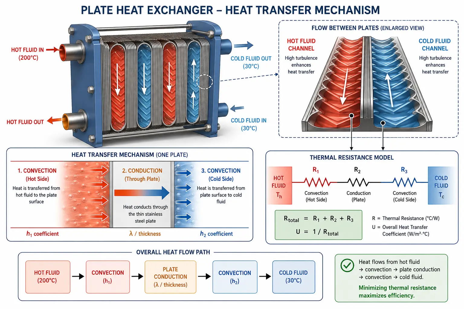
Mechanism 1: Convection
When fluid flows over a solid surface (like a tube wall), heat moves from the fluid into the solid. The effectiveness of this transfer is measured by the convective heat transfer coefficient (h). Higher fluid velocity and turbulence improve the h value. This is exactly why shell-and-tube designs use baffles and plate heat exchangers use corrugated plates—to create turbulence and boost convection.
Mechanism 2: Conduction
Once heat enters the solid tube wall, it must travel through the material to the other side. This is conduction. Thermal resistance here depends on wall thickness and material conductivity. For example, copper transfers heat rapidly (λ = 385 W/m·K), while titanium is much slower (λ = 22 W/m·K). Engineers minimize wall thickness to reduce resistance without compromising structural safety.
Mechanism 3: Radiation
Radiation involves electromagnetic heat emission. In standard liquid and gas heat exchangers operating below 400°C, radiation is negligible. It only becomes a factor in ultra-high-temperature furnace applications.
✅ Core Engineering Insight: Heat must push through multiple layers of resistance: hot-side convection, fouling scales, wall conduction, and cold-side convection. The largest resistance controls the overall performance. Because a 0.2 mm layer of calcium scale offers the same resistance as 25 mm of solid steel, fouling can easily destroy 40% of an exchanger's efficiency.
The Master Design Equation: Q = U × A × LMTD
From small domestic water heaters to massive power plant condensers, every heat exchanger is sized using one foundational thermodynamics equation.
What Each Variable Controls
| Variable | What It Measures | How to Optimize It | Typical Values |
|---|---|---|---|
| Q (Heat Duty) | The total rate of heat transfer required by the process. | Determined strictly by process requirements (mass flow × specific heat × temp change). | 1 kW (domestic) to 2,000 MW (power plants) |
| U (Overall U-value) | Combined thermal efficiency of both sides of the exchanger. | Increase fluid velocity, remove fouling, and utilize highly conductive materials. | Water-water: 1,000–3,000 W/m²·K | Gas-gas: 20–300 W/m²·K |
| A (Surface Area) | The total surface area available for the heat to transfer across. | Add more tubes, longer tubes, or fins. A higher "U" value means you need less "A". | 1 m² (small processes) to 10,000 m² (large condensers) |
| LMTD | The logarithmic average temperature difference driving the heat exchange. | Use a counterflow arrangement to maximize this thermal driving force. | 5°C (tight approaches) to 200°C (wide approaches) |
| F (Factor) | The penalty factor for deviating from ideal counterflow conditions. | Keep F above 0.75 by utilizing multiple shell passes if necessary. | 0.75 to 1.00 (below 0.75 is highly inefficient) |
Calculating LMTD: A Real-World Example
Assume hot oil enters at 180°C and exits at 90°C. Cooling water enters at 25°C and exits at 65°C in a counterflow setup:
ΔT₂ (cold end) = 90 − 25 = 65°C
LMTD = (115 − 65) / ln(115/65) = 50 / 0.570 = 87.7°C
This 87.7°C represents the effective driving force pushing heat through the exchanger. The higher your LMTD, the smaller (and cheaper) your heat exchanger needs to be.
Flow Arrangements: Counterflow, Parallel & Crossflow
The relative direction of fluid flow dictates the thermal efficiency of the design. There are three primary flow arrangements:
⇅ Counterflow
━━━━━━━━━━━━━━━━━━━━━
COLD ←←←←← 65°C ← 25°C
Highest Efficiency. Fluids move in opposite directions, maximizing LMTD. The cold fluid can actually exit hotter than the hot fluid's exit temp. Used in most industrial designs.
⇉ Parallel Flow
━━━━━━━━━━━━━━━━━━━━━
COLD →→→→→ 25°C → 65°C
Lower Efficiency. Fluids move in the same direction. The cold outlet can never exceed the hot outlet. Best utilized to prevent thermal shock in sensitive fluids.
⇋ Crossflow
━━━━━━━━━━━━━━━━━━━━━
COLD →→→→→
Intermediate Efficiency. Fluids move perpendicularly. This is the standard mechanism for air-cooled heat exchangers, where ambient air blows directly across process tubes.
📌 Counter-Intuitive Fact: In a perfectly engineered counterflow heat exchanger, a "temperature cross" can occur, meaning the cold fluid leaves the unit hotter than the hot fluid leaving the unit. This is thermodynamically impossible in parallel flow designs.
The 12 Types of Heat Exchangers Explained
The "best" heat exchanger isn't the most expensive one—it's the one uniquely suited to your fluid, temperature, pressure, and maintenance needs. Here is our definitive breakdown of industrial heat exchanger types.
The industrial heavyweight. One fluid flows through a bundle of parallel tubes, while another flows through a cylindrical shell surrounding them. Built to TEMA standards and capable of handling extreme pressures.
▶ Pressure: 5,000+ psi | Temp: 800°C+ | Market share: 50%+
Learn more →Constructed from a clamped stack of corrugated metal plates. Highly turbulent flow creates U-values up to 5x higher than shell-and-tube units for liquid duties. Easily dismantled for deep cleaning.
▶ Pressure: <300 psi | Temp: 200°C | High U-values
Learn more →Utilizes massive fans to force ambient air over finned process tubes, eliminating the need for cooling water. Highly prevalent in oil & gas and regions facing severe water scarcity.
▶ Standard: API 661 | Requires zero cooling water
Learn more →A simple, highly effective design: a smaller pipe nested inside a larger pipe. Ideal for achieving true counterflow and handling small-to-medium thermal duties involving highly viscous fluids.
▶ True counterflow | Modular sections | Easy maintenance
Learn more →Fins are wound or extruded onto tubes to drastically multiply the surface area. Because gases transfer heat poorly compared to liquids, fins compensate by creating 15-20x more contact area.
▶ Gas-to-liquid | 8–12 fins per inch
Learn more →Plates are vacuum-brazed permanently together without gaskets or bolts. Extremely compact and leak-proof, making them the gold standard for refrigeration and modern HVAC applications.
▶ Pressure: Up to 45 bar | No gaskets | Ultra-compact
Learn more →Engineered explicitly for highly corrosive seawater environments. Built with titanium or copper-nickel tubes to prevent catastrophic bio-fouling and salt corrosion on ships and offshore rigs.
▶ Ti or Cu-Ni construction | ABS & DNV-GL Certified
Learn more →Printed Circuit Heat Exchangers feature micro-channels etched into metal plates. They offer mind-boggling surface area density (up to 2,500 m²/m³), used in hydrogen production and extreme aerospace environments.
▶ Pressure: 1,000+ bar | Extreme size-to-duty ratio
Learn more →Tubes are bent into a "U" shape and connected to a single tubesheet. The floating bend expands freely, meaning it can absorb massive thermal shocks without cracking. Bundles are easily removed for cleaning.
▶ Ideal for extreme ΔT | Single tubesheet design
Learn more →A variation of the double pipe concept where multiple inner tubes are bent into a hairpin loop. Delivers true counterflow with the convenience of having both connections located on a single end.
▶ High pressure | True counterflow | Viscous service
Learn more →Spiral Heat Exchanger
Two sheets rolled into concentric spirals. Because of its single-channel flow path, it is inherently self-cleaning, making it perfect for thick slurries, sludge, and fibrous fluids that would instantly clog standard tubes.
▶ Anti-clogging | Ideal for heavy sludge and wastewater
Regenerative Heat Exchanger
Rather than continuous separate flows, a thermal mass (like a rotating wheel) absorbs heat from hot exhaust gas and physically rotates to release it into incoming cold gas. Achieves 90%+ thermal recovery.
▶ Gas-to-gas efficiency | Used in blast furnaces & turbines
Not Sure Which Heat Exchanger Type You Need?
Share your fluid type, temperature range, and operating pressure. Our certified engineers will calculate the exact specifications required for your process. No sales pressure—just reliable thermal engineering.
Get Free Engineering Advice →📄 Download Product BrochureIndustrial Applications Across 10 Sectors
Heat exchangers are the invisible backbone of modern infrastructure. Here is a look at how various industries deploy them for critical operations:

Food & Beverage
Pasteurization, CIP, juice concentration. (Plate HXs dominant).
Oil & Gas Refining
Crude pre-heating, distillation, condensers. (Shell & tube dominant).
Power Generation
Steam condensation, lube oil cooling, boiler feedwater heaters.

Chemical Processing
Reactor jacket cooling, solvent recovery, polymer processing.
Pharmaceutical
API synthesis, WFI (Water for Injection) systems, sterile condensing.
Marine & Offshore
Engine cooling, lube oil coolers, coastal platform seawater cooling.

HVAC & Buildings
Chillers, district heating networks, commercial heat pumps, fan coils.
Natural Gas
Compression aftercoolers, gas dehydration, LNG liquefaction.

Automotive
Radiators, intercoolers, and EV battery thermal management grids.

Fertilizer & Mining
Ammonia synthesis, sulfuric acid cooling, mineral processing.
Power Generation — Colossal Thermal Loads
A single 1,000 MW coal or nuclear plant relies on over 200 individual heat exchangers. The primary turbine condenser operates 24/7/365, transferring over 1,500 MW of latent heat. Packed with up to 50,000 tubes (often titanium for saltwater systems), a single microscopic tube leak would contaminate the entire power cycle. Perfection in manufacturing is mandatory.
Petroleum Refining — The Economics of Heat Integration
Refineries can recover up to 70% of their operational heat by using hot outbound product streams to preheat cold inbound crude oil. Using "Pinch Analysis", engineers string 20–30 shell-and-tube exchangers in series. By drastically reducing the need to burn fuel in fired heaters, this heat integration drives profitability and significantly lowers plant emissions.
Material Selection: Matching the Metal to the Process
Selecting the wrong material is the number-one cause of heat exchanger failure. A metal that performs flawlessly in one plant will corrode in days in another. Below is an expert guide to alloy selection:
| Material | Max Temp | Thermal Conductivity | Best Application | Avoid Using With |
|---|---|---|---|---|
| Carbon Steel | 425°C | 50 W/m·K | General hydrocarbons, steam, benign fluids | Acids, seawater, wet H₂S, chlorides > 60°C |
| Stainless Steel 316L | 870°C | 16 W/m·K | Pharma, food-grade, mild chemicals | Hot concentrated chlorides (causes SCC) |
| Duplex SS 2205 | 315°C | 19 W/m·K | High-chloride fluids, bleach, offshore rigs | Temperatures over 315°C (embrittlement risk) |
| Titanium Grade 2 | 300°C | 22 W/m·K | Seawater, chlorine, nitric acid, bleaching | Fluorides, dry chlorine, red fuming acid |
| Copper | 200°C | 385 W/m·K | HVAC, refrigeration, freshwater heating | Acids, ammonia, seawater (dezincification) |
| Copper-Nickel 90/10 | 300°C | 45 W/m·K | Coastal plants, seawater, anti-biofouling | Ammonia, oxidizing acids, high velocity flow |
| Inconel 625 | 980°C | 10 W/m·K | Gas turbine exhaust, mixed strong acids | Highly versatile, few practical limitations |
| Hastelloy C-276 | 650°C | 10 W/m·K | Wet chlorine, HCl, strong mixed acids | Strong oxidizing agents at high temps |
| Chrome-Moly P91 | 650°C | 28 W/m·K | High-temp steam, power plant feedwater | Wet H₂S (without post-weld heat treatment) |
| Aluminum 6061 | 150°C | 167 W/m·K | Automotive, lightweight air-cooling | Strong alkalis, mercury, direct seawater |
Fouling: The Silent Killer of Heat Exchanger Efficiency
Fouling refers to the accumulation of unwanted deposits—like scale, algae, or rust—on the heat transfer surfaces. Economically, it is devastating, costing global industries $4–$7 billion annually in wasted fuel, unplanned shutdowns, and excessive maintenance.
⚠ The Hidden Tax of Fouling: A microscopic scale deposit just 0.2 mm thick provides the same thermal insulation as a 25 mm block of solid carbon steel. An exchanger fouled to this degree has secretly lost 35–45% of its thermal efficiency, forcing pumps and boilers to work drastically harder.
The 6 Types of Heat Exchanger Fouling (and Mitigation Strategies)
| Fouling Type | Mechanism Explained | Most Vulnerable Systems | Prevention Tactics | Best Cleaning Method |
|---|---|---|---|---|
| Scaling (Crystallization) | Hard water minerals (calcium, silica) bake onto hot surfaces. | Cooling water systems (Shell & Tube, PHE). | Water softeners, pH control, fluid velocity > 1.5 m/s. | Chemical acid wash (HCl, citric); high-pressure water jets. |
| Biological (Biofouling) | Algae and bacteria form insulating biofilms below 50°C. | Open-loop cooling water circuits. | UV treatment, continuous biocide/chlorine dosing. | Caustic soda wash; mechanical brushing of tubes. |
| Corrosion (Rusting) | Iron oxides from upstream pipes deposit onto internal surfaces. | Carbon steel equipment in water service. | Oxygen scavengers, corrosion inhibitors, correct alloy use. | Acid pickling; mechanical brushing; particulate filters. |
| Particulate (Sediment) | Sand, clay, or suspended solids settle in low-velocity dead zones. | Shell-side baffle windows with low fluid velocity. | Upstream strainers; upflow vertical orientation. | Back-flushing; bundle extraction and hydro-blasting. |
| Chemical (Reaction) | Hydrocarbons polymerize and bake (coking) onto tube walls. | Refinery reboilers, high-temp crude processing. | Maintain temps below coking onset; inject anti-foulants. | Hot solvent flushes; steam decoking; drill-outs for hard coke. |
| Freezing (Solidification) | High-melting-point waxes or ice freeze onto extreme cold surfaces. | Wax-bearing crude oils, deep cryogenics (LNG). | Proper insulation; anti-wax chemicals; strict temp control. | Warm fluid flushes; extended solvent soaking. |
Understanding Efficiency and U-Values
The Overall Heat Transfer Coefficient (U-value) is the single most important metric for a heat exchanger. It consolidates every factor—convection, conduction, and fouling resistance—into one performance grade. A new, clean heat exchanger has a high U-value. As it fouls over time, the U-value plummets, directly increasing operational costs.
Industry Baseline U-Values (W/m²·K)
| Water to Water (Shell & Tube) | 1,000–2,500 | W/m²·K | |
| Water to Water (Plate HX) | 3,000–7,000 | W/m²·K | |
| Steam to Water (Shell & Tube) | 1,500–4,000 | W/m²·K | |
| Oil to Water (Shell & Tube) | 100–500 | W/m²·K | |
| Gas to Gas (Shell & Tube) | 20–100 | W/m²·K | |
| Gas to Gas (PCHE Compact) | 200–1,000 | W/m²·K | |
| Air Cooled (Ambient Air to Fluid) | 30–80 | W/m²·K | |
| Condensing Steam (Shell side) | 2,000–5,000 | W/m²·K |
Why are Gas-to-Gas U-Values so low? Gases lack density, possess poor thermal conductivity, and suffer from low viscosity. This results in incredibly low convective heat transfer (h-values of 20–50 W/m²·K vs. water's 5,000+). To compensate, gas-to-gas heat exchangers must be built with exceptionally large surface areas (like finned tubes or micro-channel PCHEs) to effectively transfer heat.
Expert Guide: How to Select the Right Heat Exchanger
Professional thermal engineers use a structured methodology to specify equipment. Follow these 6 steps to narrow down exactly what your plant requires:
Define Fluid Properties
Analyze corrosivity, phase (liquid/gas), viscosity, toxicity, and fouling risks.
Establish Parameters
Document flow rates, max allowable pressure drop, and target inlet/outlet temps.
Calculate Duty
Determine exact heat duty (Q) in kW or MW. This establishes the sheer size needed.
Plan for Maintenance
If high fouling is expected, demand removable bundles (U-tube) or plate designs for cleaning.
Assess Footprint
Evaluate space limits. Offshore rigs require compacts; open fields allow shell & tube or air coolers.
Apply Legal Codes
Identify regional regulations (ASME for US/Global, PED for EU, IS 2825 for India).
Quick Selection Decision Matrix
| Your Operating Condition | Optimal Heat Exchanger Type | Engineering Rationale |
|---|---|---|
| Extreme pressure (>300 psi) or temperature (>200°C) | Shell & Tube | The undisputed workhorse built for punishing thermal stress and pressures. |
| Clean fluids, limited footprint, need for frequent cleaning | Plate Heat Exchanger | 3-5x more efficient than shell & tube; easily dismantled and expanded. |
| Zero access to cooling water (or exorbitant water costs) | Air-Cooled (ACHE) | Bypasses water use completely, relying on ambient air and fans. |
| Heavy sludges, thick slurries, and fibrous wastewater | Spiral Heat Exchanger | Single-channel flow creates a self-cleaning scrubbing effect. |
| Refrigerants, district heating, moderate clean pressures | Brazed Plate HX | Completely leak-proof, highly compact, and economical. |
| Coastal plants, ships, and offshore rigs | Marine Heat Exchanger | Titanium alloys resist aggressive chloride attacks and biofouling. |
| Ultra-high pressure (>300 bar) gas systems (LNG, H2) | PCHE / Compact | Combines massive surface area into microscopic, high-pressure cores. |
| Small thermal duty with highly viscous fluids | Double Pipe / Hairpin | Achieves long, true counterflow paths with easily accessible interiors. |
Design Codes & Standards: ASME, TEMA, and API
Because heat exchangers operate under immense pressures, they are legally classified as pressure vessels. Global regulations dictate how they are built, welded, and inspected.
The core global standard for pressure vessel construction. Division 1 provides rigid design rules, while Division 2 allows for thinner walls through advanced stress analysis. A certified "U-Stamp" verifies third-party safety compliance.
▶ Globally Mandatory | U-Stamp Certification
The Tubular Exchanger Manufacturers Association outlines specific tolerances for shell & tube designs (baffles, tubesheets, nozzles). Graded into Class R (Refinery/Heavy), Class B (Chemical), and Class C (Commercial/Light).
▶ Class R, B, and C designations
Authored by the American Petroleum Institute, these codes supplement ASME/TEMA with rigorous, refinery-specific demands. API 660 covers Shell & Tube systems; API 661 regulates Air-Cooled operations.
▶ Standard for Global Oil, Gas & Petrochemical
The Pressure Equipment Directive is legally required for any heat exchanger installed within the European Union. High-risk categories mandate strict oversight from an EU Notified Body.
▶ Mandatory for all EU installations
India's domestic standard for unfired pressure vessels, functioning similarly to ASME. Commonly specified for regional refineries, fertilizer plants, and public power utilities.
▶ Domestic Indian Code Compliance
A safety-critical material standard specifically for "sour" service (wet hydrogen sulfide). It dictates alloy hardness limits to prevent sudden, catastrophic Sulfide Stress Cracking (SSC).
▶ Prevents sudden hydrogen embrittlement failures
Ready to Specify Your Heat Exchanger?
With over 35 years of engineering excellence, United Heat Exchangers has successfully deployed over 10,000 units globally—from 10 kW lab scales to 50 MW refinery giants. Provide your process data, and our thermal experts will deliver a highly competitive quote on time.
Get Your Custom Quote in 48 Hours →View Shell & Tube SpecificationsFrequently Asked Questions (FAQs)
1. What is a heat exchanger in simple terms?
A heat exchanger is a device used to transfer heat between two liquids or gases without allowing them to physically mix. It utilizes conduction (moving heat through a metal barrier) and convection (moving heat into the fluid) to cool down hot processes or heat up cold ones efficiently.
2. What is the difference between a heat exchanger and a boiler?
A boiler *generates* its own heat by burning fuel to turn water into steam. A heat exchanger does not create heat; it simply *moves* existing heat from one fluid stream to another.
3. Why is LMTD important in heat exchanger design?
Log Mean Temperature Difference (LMTD) represents the true average temperature difference driving the heat transfer. Maximizing your LMTD (typically by using a counterflow design) allows you to use a physically smaller, more cost-effective heat exchanger to achieve the same heating or cooling goals.
4. How does fouling affect heat exchanger performance?
Fouling (the buildup of scale, sludge, or rust) acts like a heavy blanket of thermal insulation on the metal tubes. Even a fraction of a millimeter of scale can severely choke heat transfer rates, decreasing efficiency by over 35% and forcing pumps to expend more energy to maintain flows.
5. Which type of heat exchanger is the most efficient?
For clean liquid-to-liquid applications, Plate Heat Exchangers are the most efficient, offering U-values up to 5x greater than traditional shell-and-tube models. However, "efficiency" is subjective based on the application; shell-and-tube models remain the most robust for handling dangerous pressures and extreme temperatures.
6. Is a condenser the same as a heat exchanger?
Yes. A condenser is simply a specific category of heat exchanger utilized to remove latent heat from a vapor, converting it into a liquid. While every condenser is a heat exchanger, not every heat exchanger operates as a condenser.
7. What do ASME and TEMA certifications guarantee?
An ASME certification (U-Stamp) legally guarantees that the equipment's pressure vessel integrity has been rigorously tested and inspected. TEMA certification guarantees that the internal mechanical design (baffles, tube pitches, clearances) complies with the highest standards of the Tubular Exchanger Manufacturers Association.
8. How do I know when to clean my heat exchanger?
Do not wait for a complete blockage. Track your Overall Heat Transfer Coefficient (U-value) or monitor the pressure drop across the unit. A sustained 10–15% drop in efficiency, or a noticeable spike in pressure drop, signals it is time for a scheduled cleaning cycle.
Why Choose United Heat Exchangers?
United Heat Exchangers Pvt. Ltd, based in Coimbatore, Tamil Nadu, is a globally recognized premier manufacturer. For over 25 years, we have engineered shell-and-tube, plate, air-cooled, and marine heat exchangers for leading industrial facilities across five continents.
- ASME U-Stamp & R-Stamp Facility: Every pressure vessel undergoes rigorous, independent code inspection.
- ISO 9001:2015 Certified: Flawless quality management spanning procurement, welding, and final testing.
- TEMA Class R, B, & C Manufacturing: Heavy-duty capabilities built for the world's most demanding refineries.
- API 660 & API 661 Licensed: Trusted by top-tier global Oil, Gas, and Petrochemical developers.
- Elite In-House Thermal Design: Leveraging HTRI, HTFS, and ASPEN EDR software for pinpoint accuracy.
- 100% Material Traceability: Mill certificates (EN 10204 3.1) and PMI testing performed on every alloy component.
- Comprehensive NDT Testing: RT, UT, MPT, and hydrostatic tests at up to 1.5x design pressure to ensure zero leaks.
- Global Export Readiness: Fully compliant with PED/CE, IS 2825, and major Marine Class societies (ABS, DNV-GL).
- Rapid 48-Hour Quotes: Free preliminary thermal design and budgetary pricing delivered fast.
- Lifetime OEM Support: Retubing, spares, and 24/7 technical troubleshooting provided for the lifespan of your unit.
Our Manufacturing Envelope: Shells from 50 mm to 2,000 mm in diameter. Surface areas ranging from 0.5 m² up to 5,000 m². Handling extreme pressures (full vacuum to 350 bar) and temperatures (−196°C cryogenics to 650°C). Any fluid. Any code. Any industry.
Start Your Heat Exchanger Project Today
Whether you know exactly what specifications you need, or you need our engineers to solve a complex thermal bottleneck—United Heat Exchangers is ready. Share your process conditions with us today and receive a comprehensive engineering recommendation and quote within 48 hours. Completely free and zero obligation.
Request My Free Engineering Quote →📄 Read More Technical GuidesExplore Our Complete Product Range: Shell and Tube | Plate Heat Exchangers | Air Cooled | Finned Tube | Double Pipe | Marine Grade | Compact PCHE | Brazed Plate | Hairpin | Pressure Vessels
Author: Senthil Kumar, Technical Director — United Heat Exchangers Pvt. Ltd | Published: March 2026 | Category: Heat Exchangers | Last Updated: August 2026